Week 9 - Project - Master Section Development
OBJECTIVE --
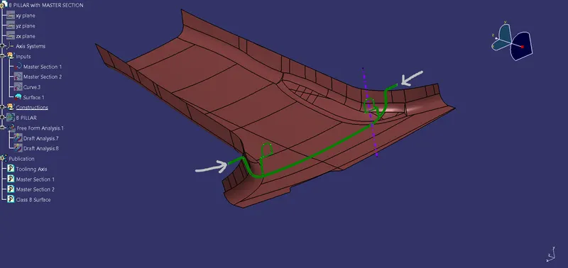
Here I have provided with the Master Section as well the Class A Surface of the B PILLAR.I need to update the Class A with the Help of the Master Section & to Create all the given Class B features & the part of the B pillar.
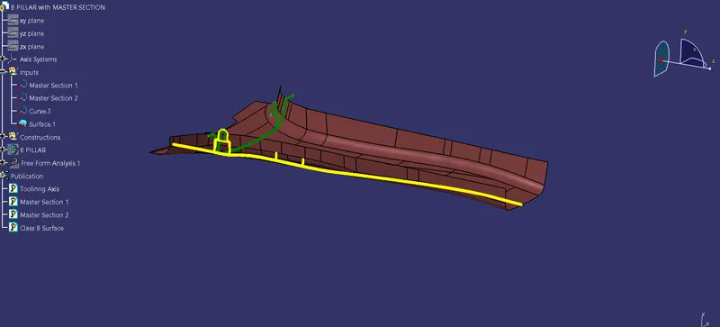
(above image shows the Inputs that are given )
As the above pic shows I had given a Class A surface & 2 major Master Section(Green Curve & Yellow Curve)
PROCESS
- Before Proceed further for creating somthing first we need to check the Boundary for given Class A Surface.
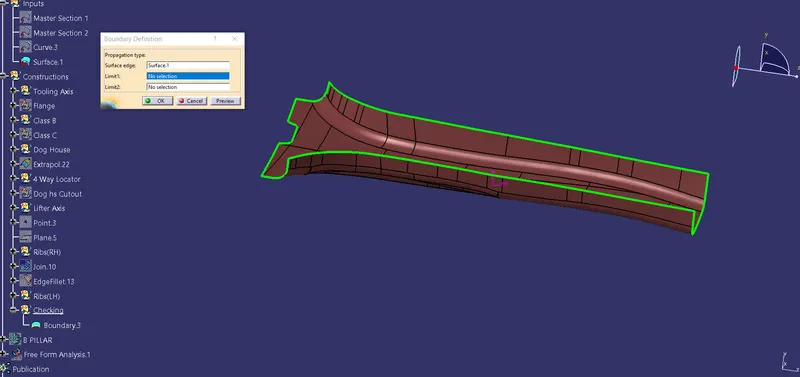
- In above pic I performed the boundary operation on class A to check for any gaps,open patches etc.
- As we don't find any such patch we can proceed further to create the TOOLING AXIS.For Tooling Axis of this part we need to take the reference of the Master Section Curves.
- We know the tooling axis can be created by BISECTING METHOD.For creating that we EXTRACT the LINES from the MASTER SECTION.Then to get a point in between we Select the Lines.After Getting the POINT in between we Can Create the AXIS line on that Point with POINT & DIRECTION option.
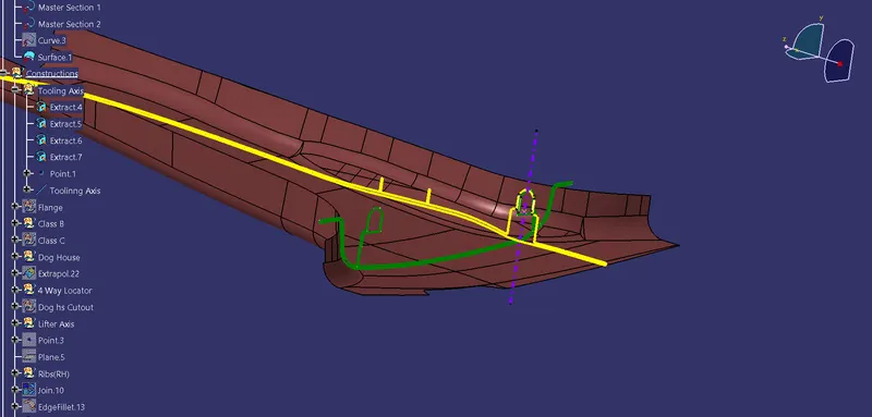
- Now we have our Tooling Axis ready with us.so we need to check the Part whether in Class A there is draft present or not.
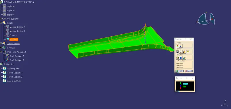
- The above figure shows the Draft Analysis for the given Class-A with 0.5deg that with our tooling axis direction we can create this part there is no such portion we can't create in this part(as the part is fully Green).
- Next step for our process will be CREATING THE FLANGE on both the sides of the surface.
- Above figure shows that in given Class A the Flange is not there we need to make the Flange for Class-A surface & proceed further.
- To Create Flange on side of Class-A first of all we need to Extract the reference line form the Master Section the Extract The Curve on which we need to create the Flange.
- Now SWEEP the line with the Guide curve With Reference Surface.
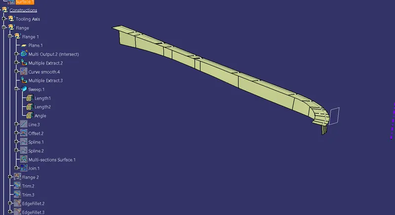
- Now Same way create the Flange on the other Side --->Then TRIM both created surface with the main Class-A Surface to get desired Output.
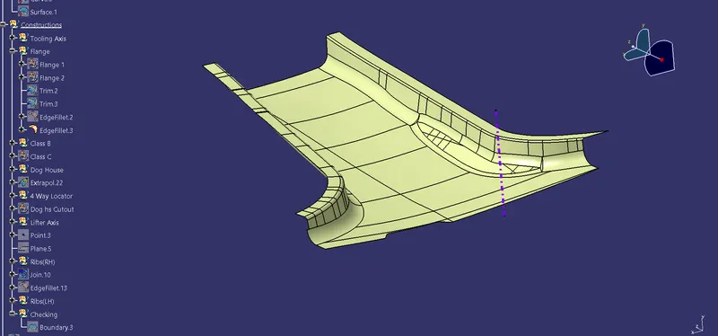
- Now we have updated the Class A with Flange on it.
- From Master Section we can have the value for the part Thickness ie; 2mm for B PILLAR part.
- Now we have to OFFSET the Updated Class A upto 2mm
- To perform the Offset Operation we have to separately OFFSET the Surfaces as shown in below Fig.
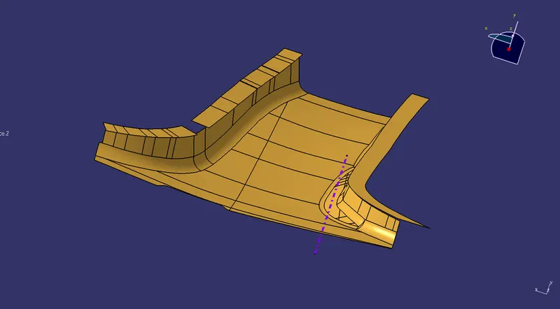
- As the above fig shows the after offset we need to perform some Alteration for making this part into one single Part.To do that we need to fill up the patches(by peforming the MULTI SECTION SURFACE and join them all together.)
- After Performing the above operations we will get the Fianl Class B surface.(shown in below image).
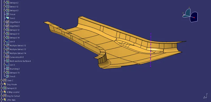
- As the Class B is ready we need to make the Classs C surface for the B PILLAR with the Help of Updated Class A surface.
- To Create the Class C we need to Perform SWEEP operation on the Class A surface with 3deg draft on it & then Join that Created Surface with the CLASS A surface to get our desired CLASS C surface.
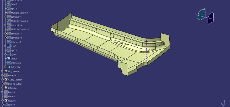
- Now TRIM the created CLASS-C & CLASS-B to get our Desired result.
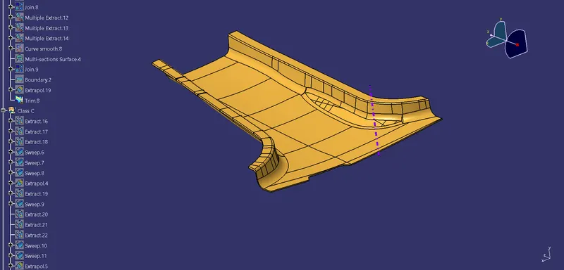
- Now To convert this Surface INTO PART -------->Go to part W/B & Select Close Surface.
- Now our B pillar part is ready.
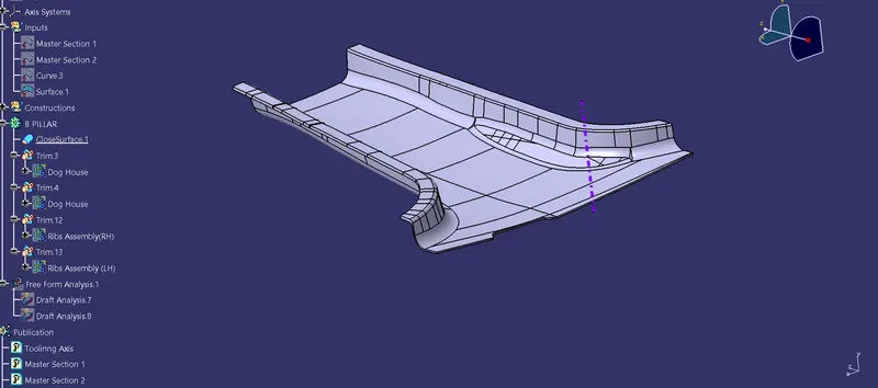
- Now we can proceed further for creating the B SIDE FEATURES such as DOG HOUSE & RIBS.
- For Creating the Dog house we need to take reference from the MASTER SECTION.
- Extract the line from the Master Section & Create the Sketch of the dog house.Now extrude it to get our desired shape.
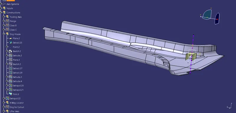
- Now Thicken this surface to 2mm to convert this into solid body.
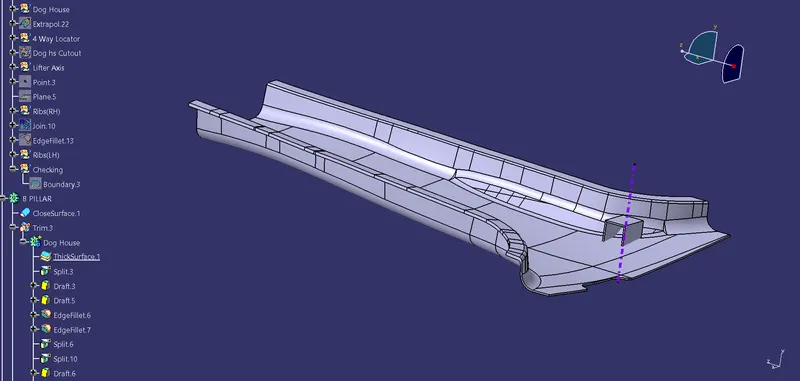
- Now apply some draft in the inner part of the body & also we need to make the 4 way locator on top of it & ADD that part to dog house part.
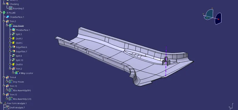
- Now our B side feature(Dog House) is ready but we need to ckeck this newly created part by performing the DRAFT analysis on it.
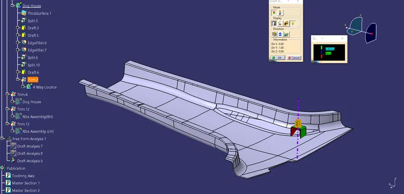
- This above figure shows that the dog can be cleared by the Tooling Axis but for inside we need to make the SIDE CORE AXIS/LIFTER AXIS.For inside we need to perform the draft analysis on the lifter axis .
- Now Copy the created Part & Paste Special-------->Result with link.
- Now Perform SYMMETRY operation with the mid plane in between.
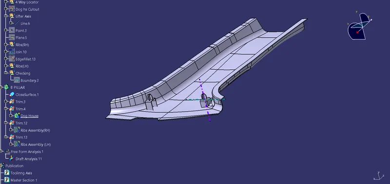
- As both the dog house created we need to proceed for creating the ribs on the side .
- To create the rib for this part we need to SKETCH a line from 50 mm apart from the dog house--------->Then Extrude that line ------->Then thicken that part upto 0.8 get our RIB part.
- Now offset local surfaces of Class B upto 10mm for maintaining the height of the RIB.Perform SPLIT operation to get a desired height.Then we have to create similar parts upto last end.To do that we need to MULTIPLE EXTRACT the Curve & create 9 points on that curve.
- Then Perform Translate option onn every single Rib.
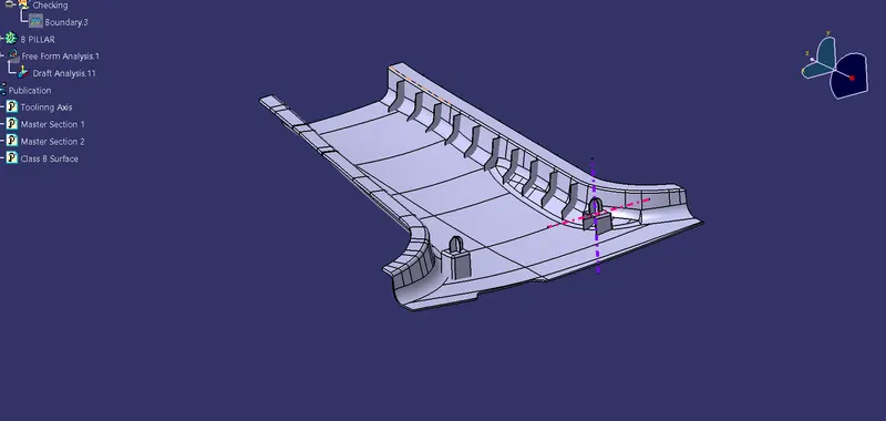
- As the RIBS ASSEMBLY Created we need to Perform the UNION TRIM operation for trimming option.
- Similarly create ribs on the other side of the B pillar.
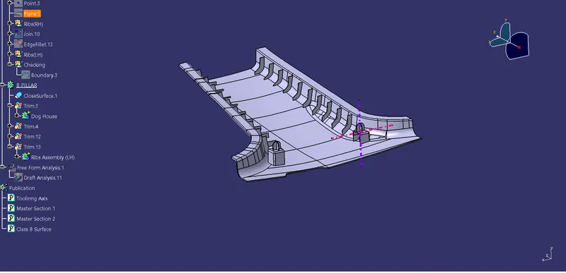
THESE ARE THE STEPS/PROCESS THAT I HAVE FOLLOWED TO CREATE THIS B PILLAR PART.