Week 9 - Project - Master Section Development
AIM
The aim of this project to model the B pillar component along with the required attachment features using the given Class-A surface and
the master section of the component.
THEORY AND PROCEDURE
Class A surface of a component refers to the aesthetic surface which is visible to the naked eye when we observe a body(such as a car). In
general, they are high-quality surfaces which have some fine finishing and aesthetic look to it. As plastic components are injection moulded,
we need a tooling axis for the core and the cavity. The tooling axis/direction is the direction in which the moulds(core and cavity) move
apart/together which means it serves as the reference to design your data up against. One more point to be noted here is that the draft is
always provided along the tooling axis so that it can easy when the component/mould are parted.
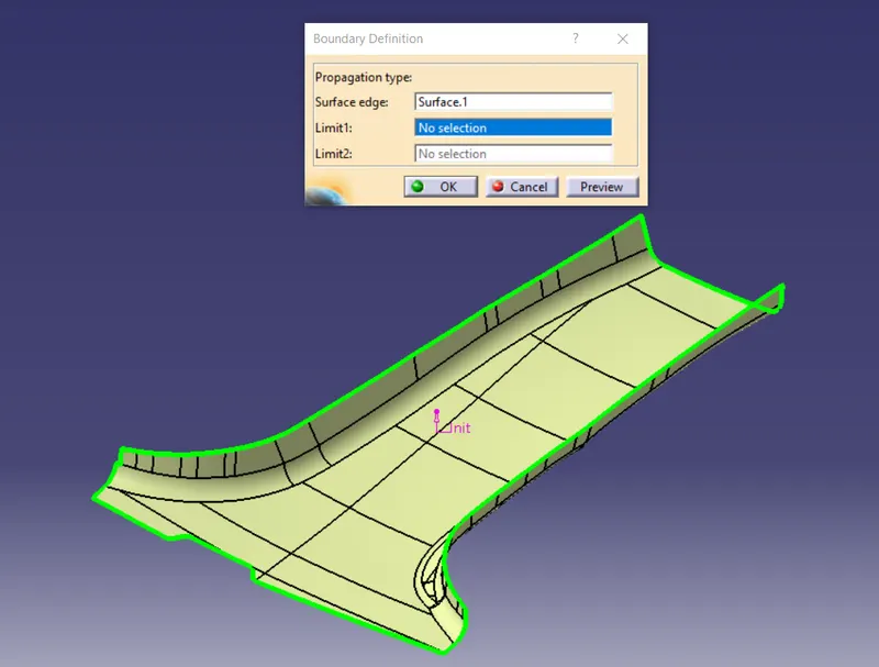
BOUNDAY IS FULLY CLOSED THERE IS NO OPEN EDGES FOUND.
TOOLING AXIS
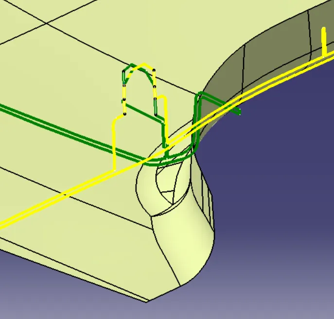
Extract the edges of the given master section of the part
 .
.
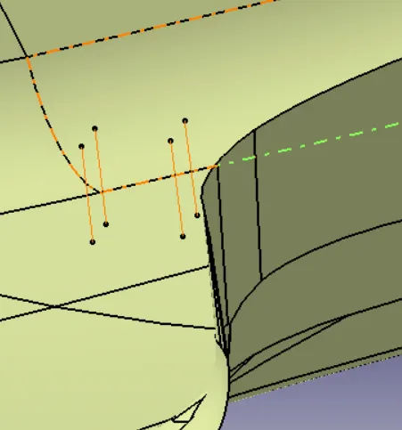
use the comand in ponit of between so that select the two point and give middle to draw the tooling axis
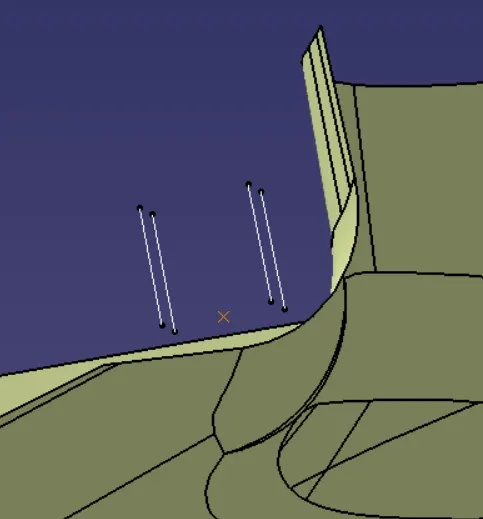
Main tooling axis is created then perform the draft analyis of the give class A surfce part
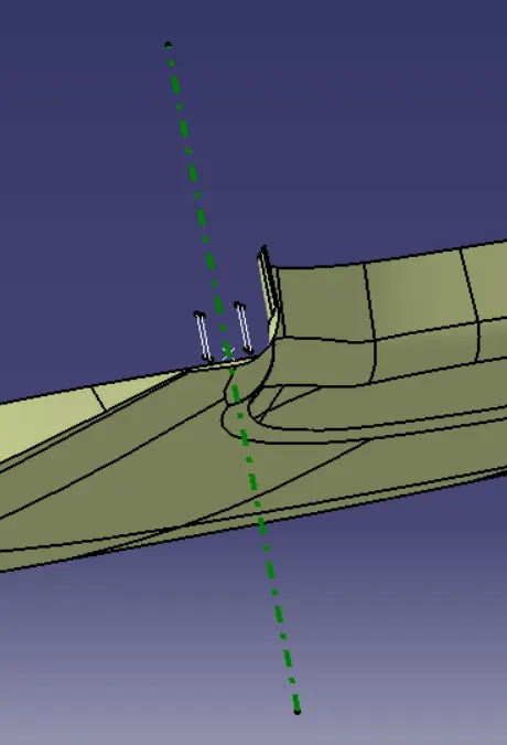
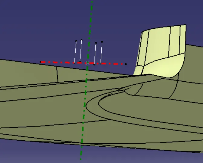
and aslo create the side core axis to give the ejction claernce for the part of side core part
Draft Analysis
The Draft Analysis command enables you to detect if the part you drafted will be easily removed. This type of analysis is performed on color ranges identifying zones on the analyzed element where the deviation from the draft direction at any point, corresponds to specified values.Draft angles are very important in thermoforming product design. If the product is formed onto a female or negative mold, it shrinks from the mold sidewalls. As a result, true female or negative products can be thermoformed with vertical walls having zero draft angles. Parts Cannot be ejected from the tool if it is at 90 degree surface.for the reason,A small Draft angle is to be provide for each every surfaces of the Component in order to easy removal of component from the moulds without any defects.Draft is the angle in the part is tapered to aloow it to release.Most of the part require minimum 1/2 degree to 1 degree however 3 degrees are widely accept plastic component design.Draft Analysis is the technique used to analise weather our designed product are manufacturable with required conditions or not.
Importance of DRAFT in Injection Molding:
• Reduces the chance of damage to the part due to friction during release
• Reduces wear and tear and chances of damage to the mold
• Ensures a uniform, smooth, unscratched finish when required
Ensures the integrity and uniformity of other surface finishes and textures
• Reduces overall cooling time by lessening or eliminating the need for unconvent
• Most, if not all, of these benefits offer either direct or indirect overall production
Steps followed for Draft Analysis:
The part created has to be changed to material mode in display frame.
• Compass is enabled. Align compass along with tooling direction.
Lock command is then applied to fix compass along withy tooling axis
Color codes are classified and Draft angle is applied.
• Running point analysis is used to display permissible draft angle.
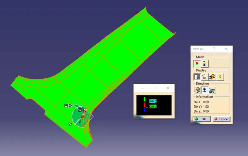
As we can observe from the image above, the class A surface on its own has some issues as it does not clear for the minimum draft angle clearance. This cannot be rectified by us as it is provided by the team performing the class A styling/surfacing. Keeping this in mind, we proceed to class B surface creation. We use the given master section of the final component to find the thickness of the component and thereby deciding the offset value for class B surface.
CREATING CLASS B SURFACE
B Class Surface Creation
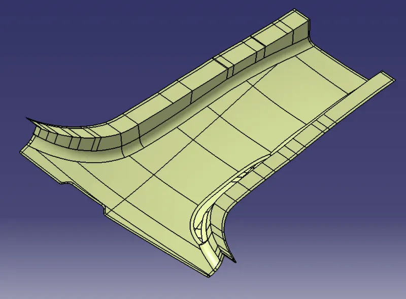
Represent internal and/or functional surfaces. This cluster exemplary includes derived surfaces created by offset operations from class A surfaces to define the thickness of material. In this file it is important to link class B surfaces geometrically to enable an adaptation to class A surfaces automatically in case of styling change.
After creating the tooling axis, B surface is to be created which is nothing but the surface parallel to the A surface. B surface contains all the fillets and the edges which the A surface contains.
CREATING CLASS C SURFACE
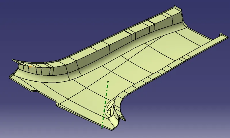
C Class Surface Creation Class C Surface is swept along the boundry of the Class A at an angle perpendicular to the CLASS A surface with right direction with a draft angle of 3 degree.
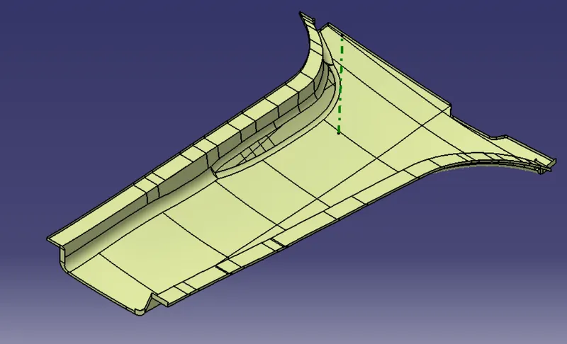
After creating class C surface merge class A with class C and trim with class B surface
TRIM WITH CLASS B SURFACE
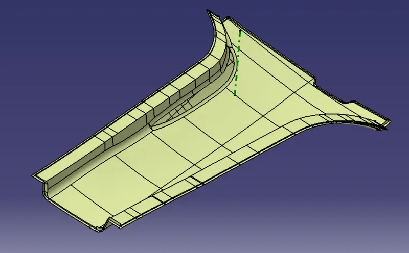
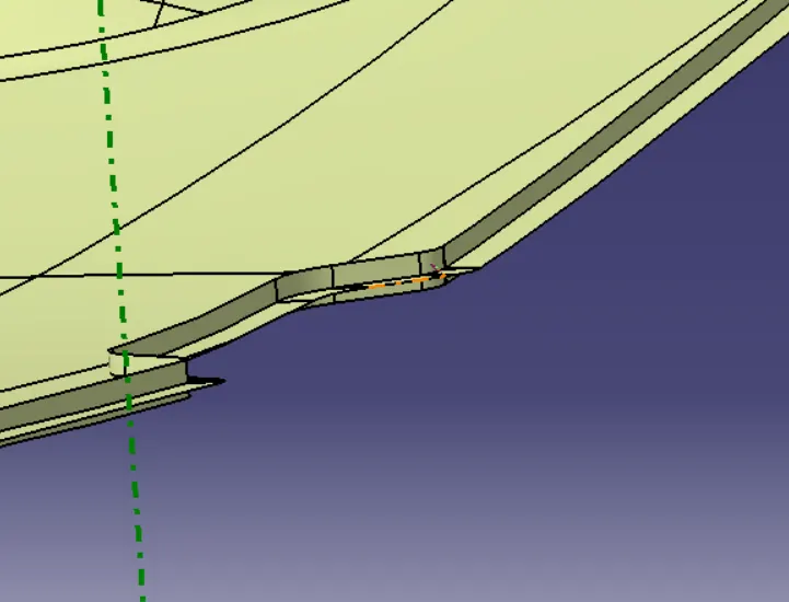
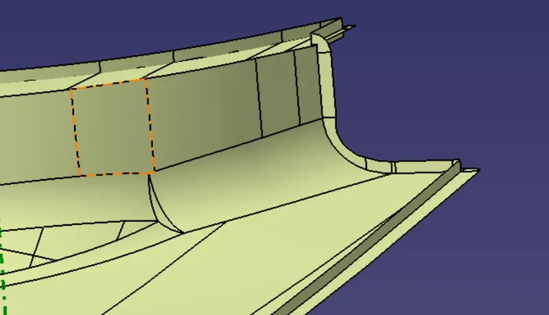
Requried part is ready check for the close surface
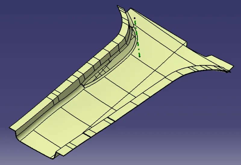
Close surface is formed and part body is created and performing the draft analyis for the body
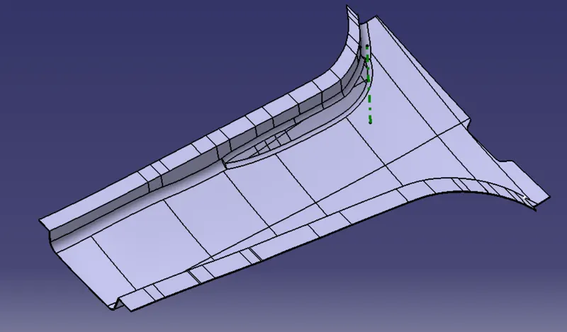
DRAFT ANALYSIS
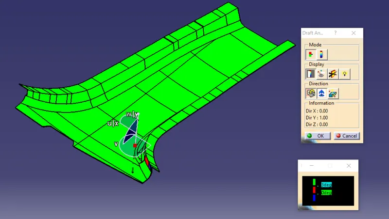
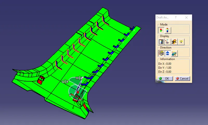
MOST OF THE FACE ARE CLARING ALONG WOTH THE TOOLING AXIS OF THE PARTAND CKECKING THE PART SIDE FOR THE PART EJECTION PART
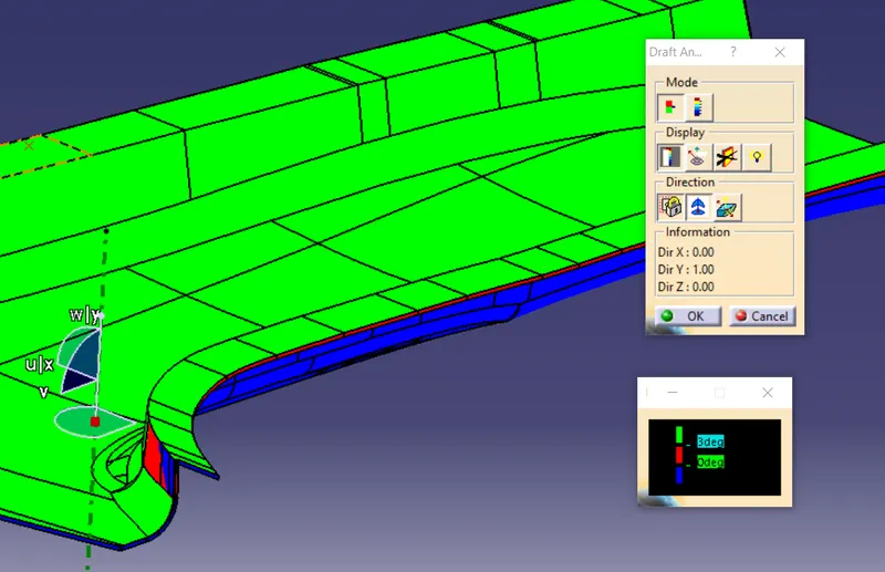
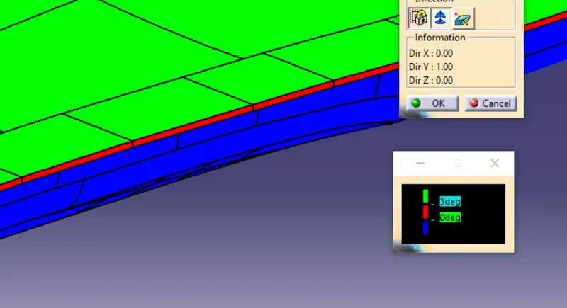
AS PER DESIGN RULES SIDE PART MUST HAVE MIN OF 0.5 DEG DRAFT SO WE HAVE RED COLOUR THAT WE HAVE THE MIN DRAFT ANGLE TO CLEAR THE PART ALONG THE TOOLING AXIS
DOG HOUSE
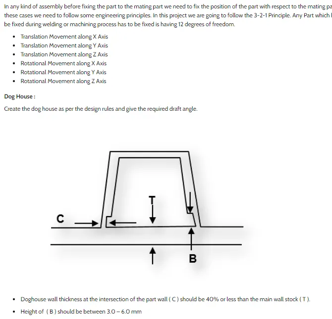
ACCORDING TO THE GIVEN THE MASTER SECTION WE HAVE WELL KNOW THAT THE ITS A FOUR WAY CONNECTOR FO THE DOG HOUSE
We can observe that the draft is good for the component except for the region where there was an issue with the class A surface. After this,we proceed to the creation of B side features. We create ribs and 4-way locators(mounted on a doghouse) as we can observe them in the master section and hence should be present in the component.
We create the required sketches for the doghouse, extrude them to obtain a surface and then thicken it to obtain a solid. After this, we provide the necessary draft and fillets. After this, we create the gate on the inner side of the doghouse while ensuring that the design guidelines are followed. For this region, we need a side tooling axis as this region cannot be cut out using the main tooling axis and hencerequire a lifter for it. We perform a draft analysis for that region as well using the lifter axis as the reference.
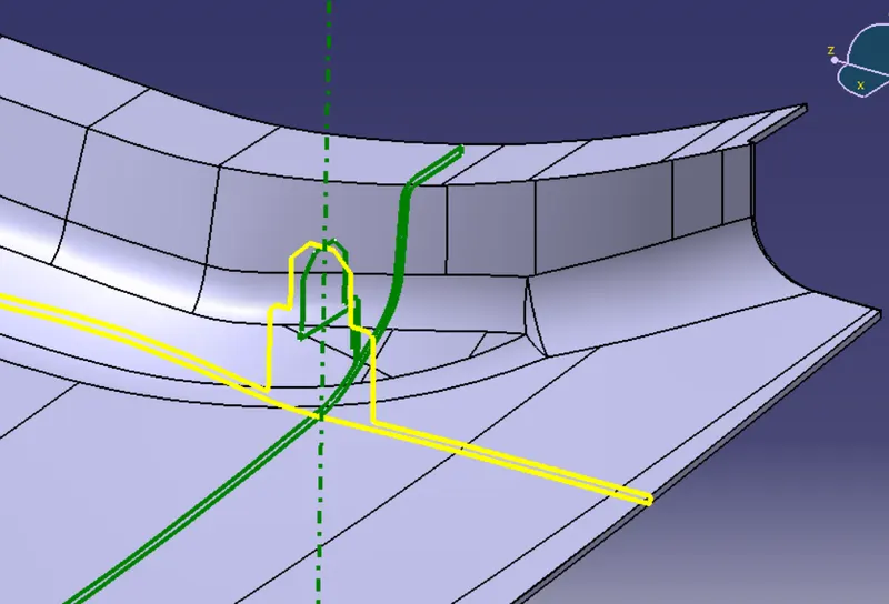
CREATE A SKETCH BY ACCORDONG TO THE GIVEN MASTER SECTION PART
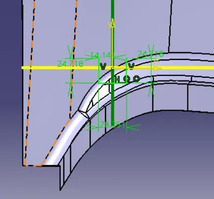
EXTURDE THE LINE BY THE SURFCAE OF THE PART
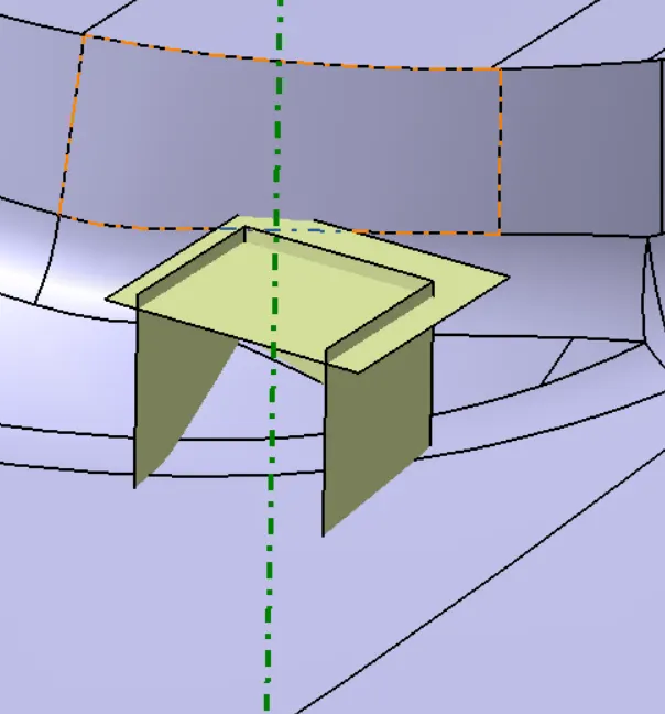
DOG HOUSE IS CREATED
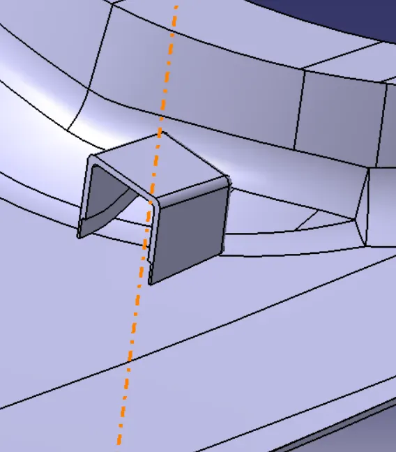
FOUR WAY CONNECTOR ON THE TOP OF DOG HOUSE
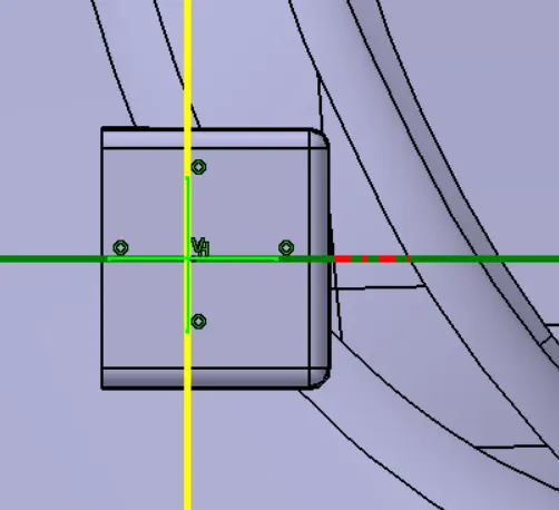
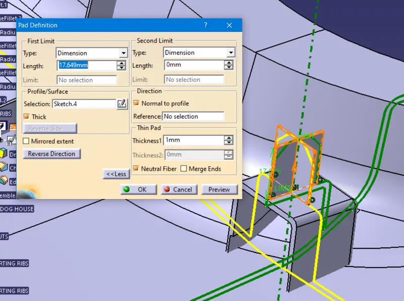
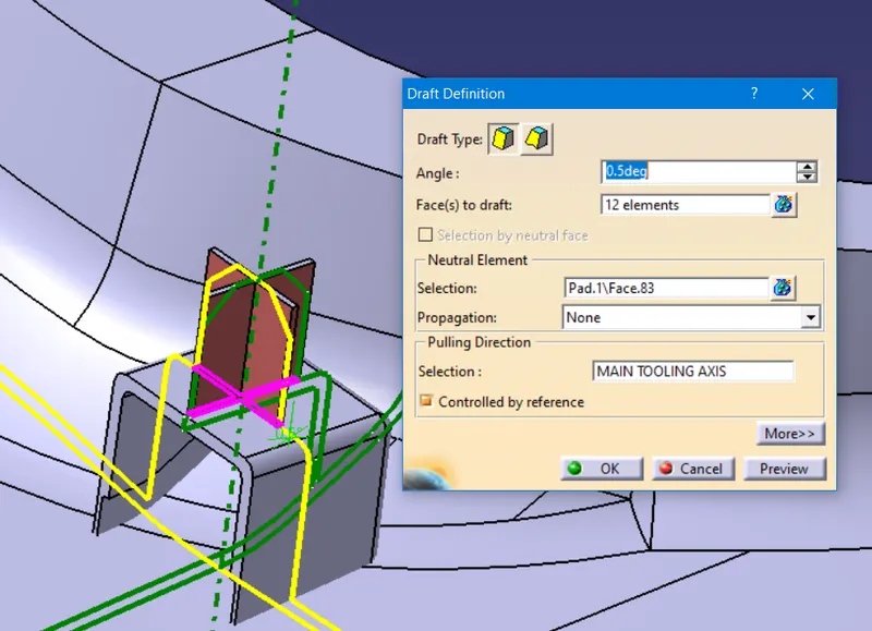
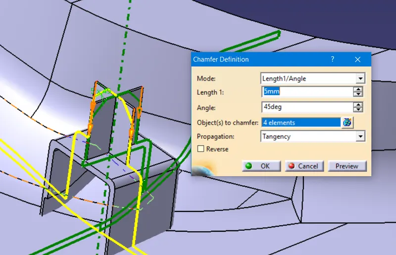
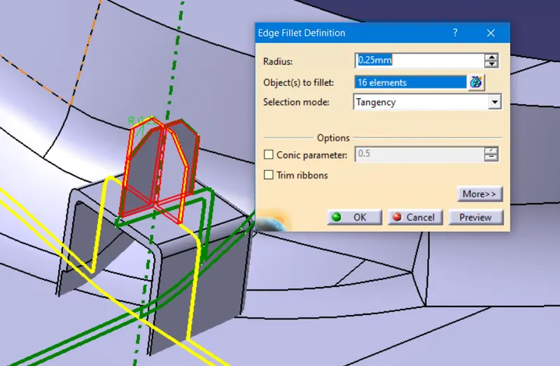
FOUR WAY CONNECTOR WITH DOG HOUSE
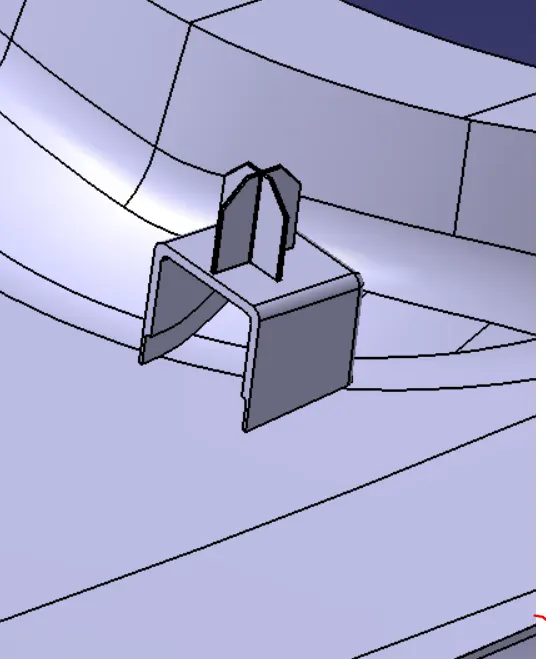
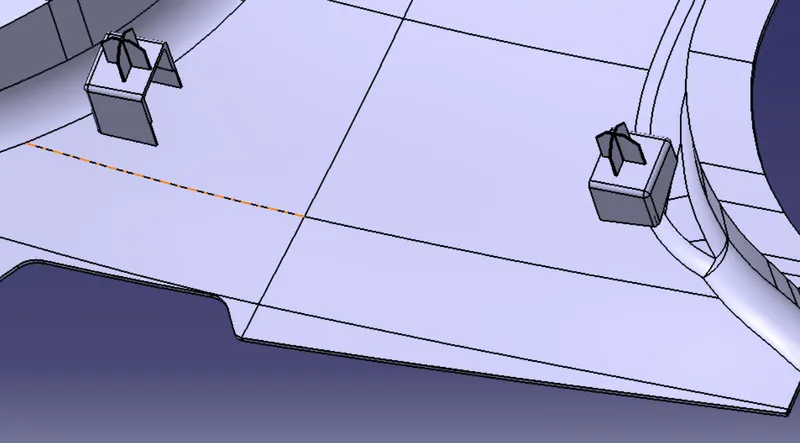
TRANSLATE THE DOG HOUSE WITH FOUR WAY CONNECTOR ON OPPOSITE SIDE
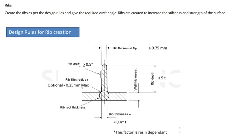
RIBS ON MASTER SECTIONS
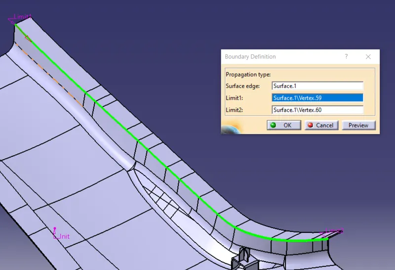
CREATE A BOUNDARY LINE AND MAKE A PARALLEL CURVE
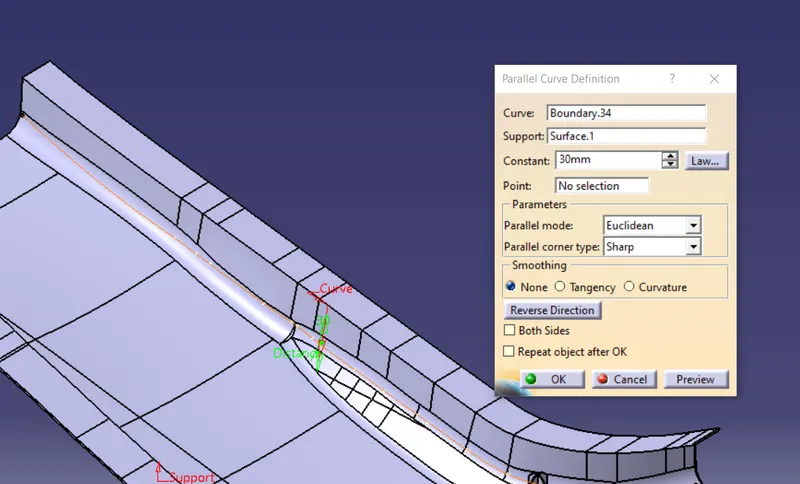
CREATE A POINT USING POINTS AND PLANE REPETATION METHOD
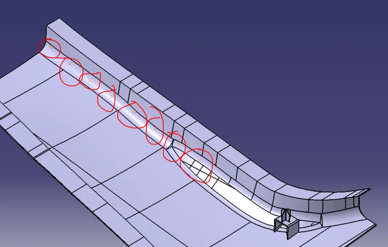
AND TRANSLATE THE PARTS ON EACH POINTS
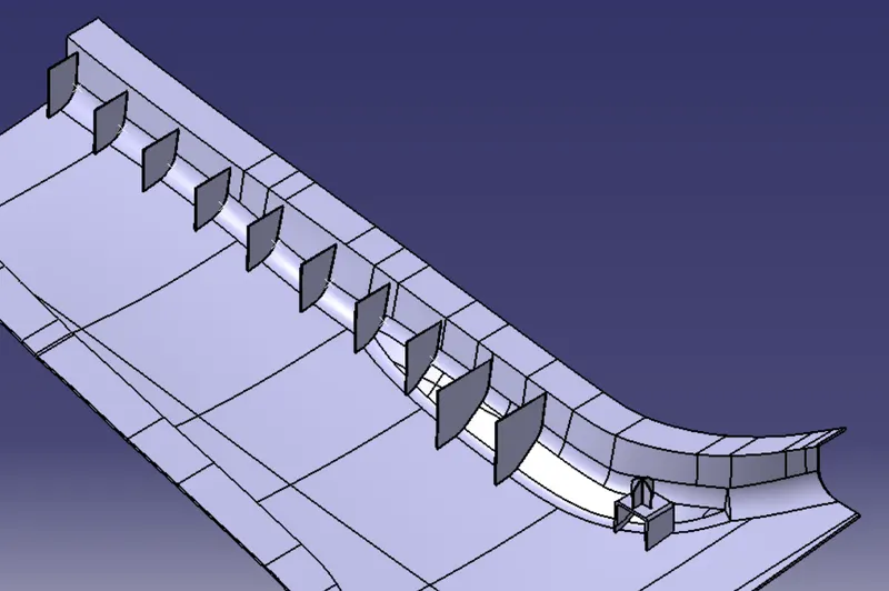
CUT THESE FRONT HALF SURFACE FROM THE OFFESET PART AND GIVE THE MIN DRAFT VALUE OF 0.5DEG
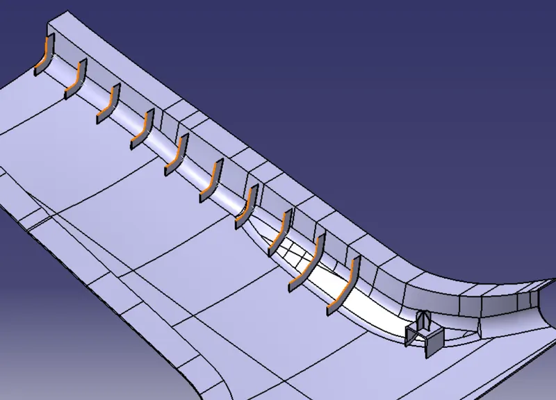
SIMALITLY ON OTHER WILL BE CREATED
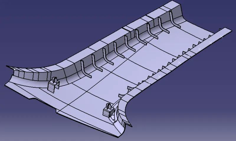
DRAFT ANALYIS IN MAIN CORE AXIS DOG HOUSE OUTER SIDE IS ALL CLAERING THE EJECTION PART
SIDE CORE AXIS
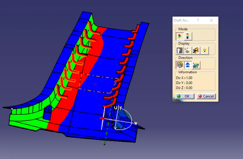
USING SIDE CORE DOG HOUSE INNER AND RIB ALL THE FACES ARE CLEARING THE EJECTION PCROCESS
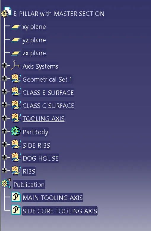
TREE STRUCTURE