Week 9 - Project - Master Section Development
Objective:
1) Create a tooling axis for the given component .
2) Create B surface and C surface for the given Class A surface.
3) Create a solid component using a closed surface from the above surfaces .
4) Create B side features (Ribs and Screw Boss) as per given master section .
Answers:
1) Creation of tooling axis for the component from given master section.
Procedure :
Step 1: Import the model and check for surface continuity and connectivity using Join tool .Ensure there is no surface gap . Create a geometrical set and name it tooling axis
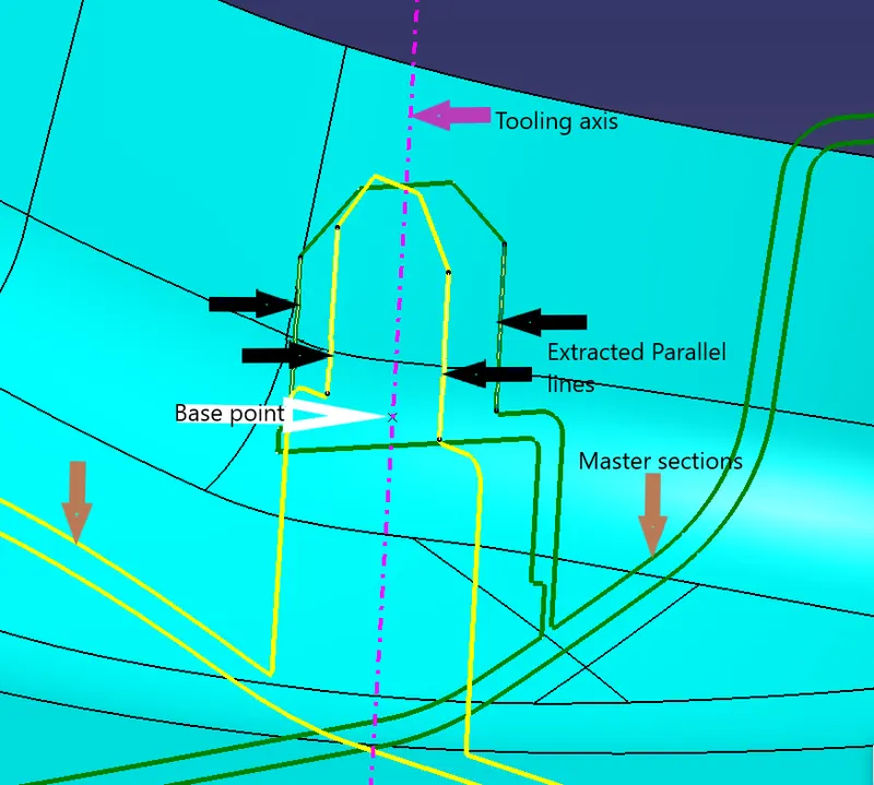
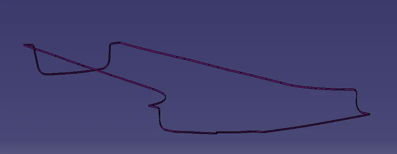
Step2: Unhide the master sections and extract 2 parallel lines each from the master sections using extract option .
Step 3: Create a point between these two lines using point in between option .
Step 4 : Create 2 bisecting lines between these parallel lines of same master section with above point as base point .
Step 5: Now create a line bisecting the above 2 bisecting lines . This is out required tooling axis as per given master section .
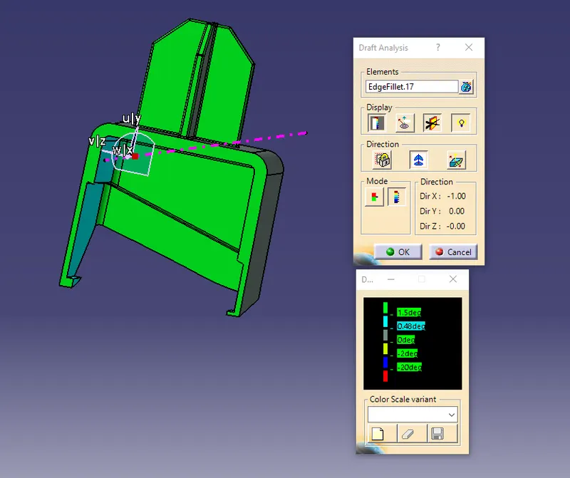
Step 6: Perform Draft analysis on the above component using tooling axis .
Procedure to check for Draft analysis
1)Once the tooling axis is created , publish it and the component using Publication from tool option .
2)Insert Feature draft analysis option from insert tool bar
3) Change the view option to customize view parameters and click on material option under shading .
4) Now click on the axis option from Draft analysis tools , allign it with tooling axis and click on lock option to lock it .
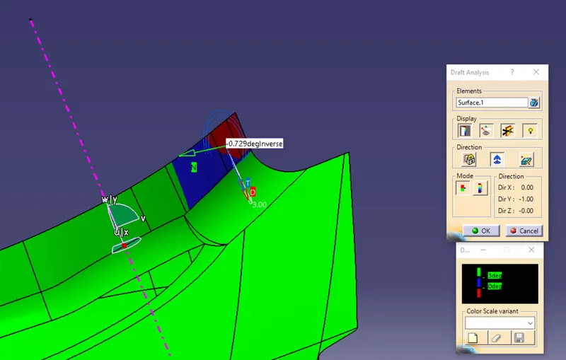
5) Change draft angle value to 3 degree . Click on quick analysis mode to display feature according to given color scale . Check from all views to ensure the draft analysis is cleared .
Here we can observe that tooling axis created does not clear draft analysis on all regions . There are some areas where negative draft is present .
2) Creation of B and C surfaces .
Procedure for creation of B surface
Step 1: Offset the A surface by the value of 2mm given as thickness .
Step 2 : Now to create the flanges as per given master section ,extract edges of Class A using multiple extract option and use smooth curve to remove any point discontinuities .
Step 3: Use sweep using guide curve and draft direction to create surfaces according to draft direction .
Step 4: Use trim option to remove the excessive surface and apply fillets to obtain required flange .
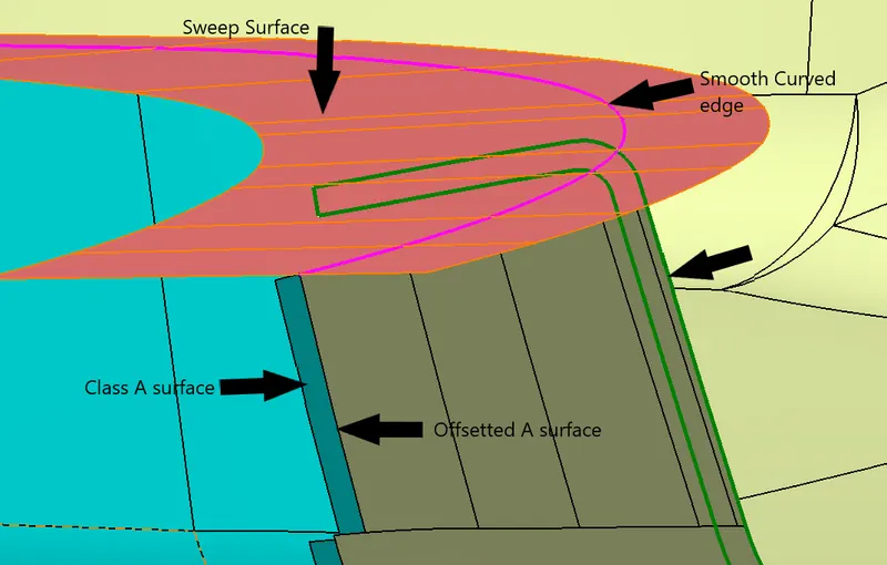
Step 5: Perform the steps 1-4 on both sides to obtain flanges on Class A surface . Name and Publish it as imroved Class A Surface.
Step 6: Now offset both swept surfaces by thickness value(2mm) and trim them with offseted class A to obtain B surface .
Step 7: Extrapolate or sweep all the edges of above surface to obtain completed b surface .
Step 8: Rename and Publish the above surfacfe as Completed B Surface .
Improved class A and B Surfaces
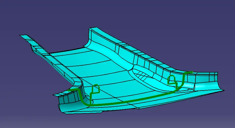
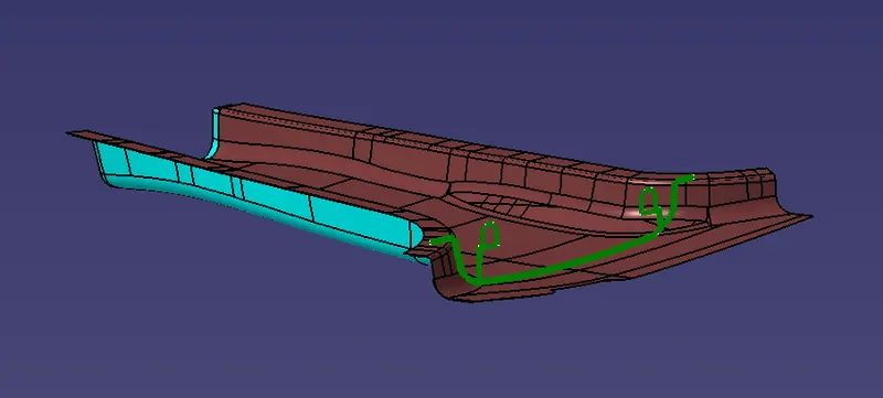
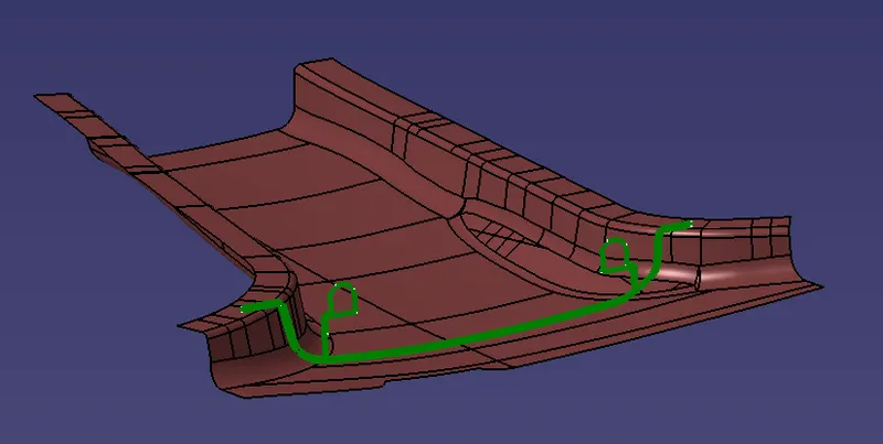
Procedure to create Class C surface
Step 1: Use sweep along draft direction to obtain surfaces joining A surface and B Surface . In some areas, Sweep command might not give proper results . In those areas , use multisection surface command to obtain reqired surface along tooling direction .
Step 2: Use extrapolate to extend the swept surfaces so that they intersect along perpendicular surfaces .
Step 3: Use trim command to join and trim off excessive surfaces .
Step 5 : We have obtained Class C surface . Rename it and Publish .
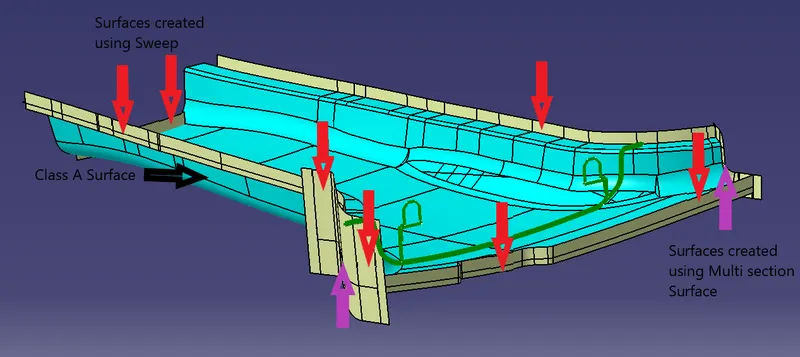
Completed C Surface
3) Procedure to create a solid body from above 3 surfaces .
Step1: Insert a new geometrical set and name it final trims .
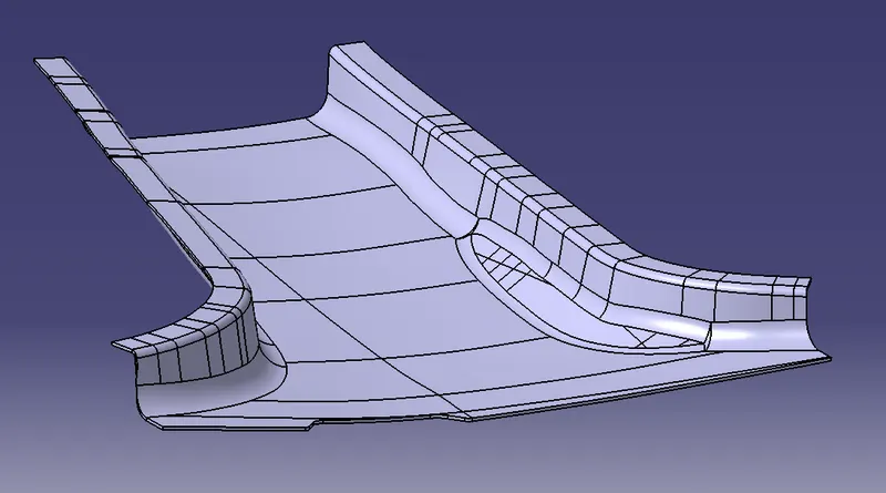
Step 2: Use trim option to combine A,B and C surfaces and obtain a closed sirface .
Step 3: Insert a new body and name is solid .
Step 4: Use close surface option to create a solid from the above surface .
4) B surface Features
4 way locators : 4 way locators are a type of locator used to constrain the movement of a component about 2 axes(+x,-x,+y and -y) . They are used in molded parts to fix it in a particluar location .
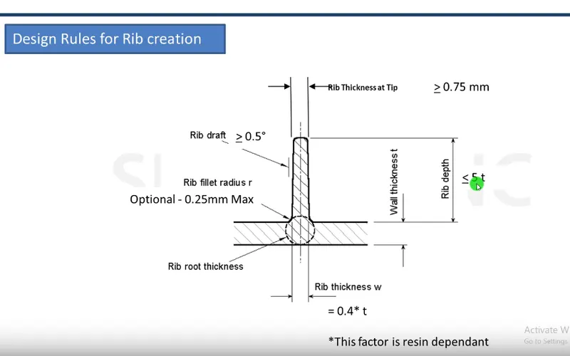
Ribs : Ribs provide means to an economical stiffness and strength in molded parts without increase in overall wall thickness . They also facilitate
a) locating and arresting components of an assembly
b)Provide allignment in mating parts
c)Acting as stops or guides for mechanisms.
Design Considerations for ribs
Procedure to create dog house :
Step 1: Insert a new geometrical set and name it as dog house . Create a positioned sketch parallel to master section plane .
Step 2 : Project the master section lines into the created plane . Iso constrain the sketch .
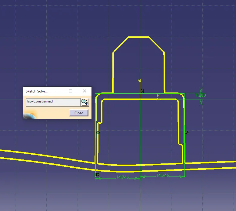
Step 3: Exit the sketch and extrude the sketch along x axis to some distance in both direction . Use the other smaster section to get accurate measurement of the extruce .
Step 4: Trim the above extrude from required dimension obtained from other master section to obtain a cuboid with 4 faces .
Step 5: Insert a a new body and name it dog house . Use thick surface option to give thickness and create a solid from the above surface .
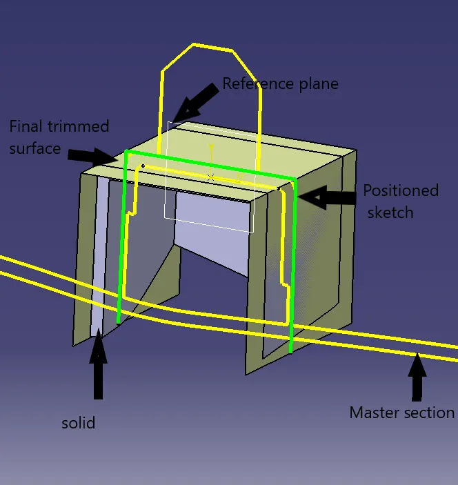
Step 6: To create the inner side of the dog house , create another geometrical set and name it dog house inner .
Step 7: Project the inner surface from master section to create an Iso constrained positioned sketch with required profile .
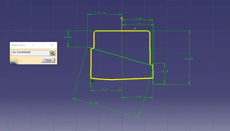
Step 8 : Extrude this surface in both direction . Make a note , not to extend it beyond the thickness value on the rear face of the dog house .
Step 9: Use extract and extrapolate option to create in closed surface of required shape .
Step 10: Create a solid after creating a new body and defining it .
Step 11: Use remove boolean operation with the above dog house body to obtain the required dog house shape .
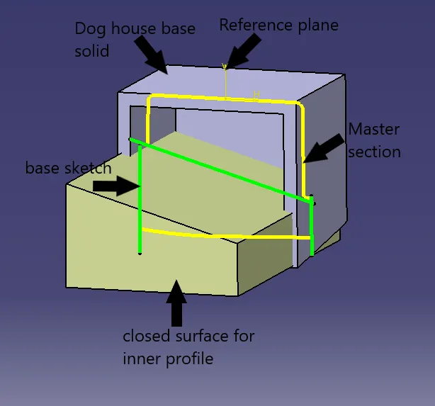
Final dog house body after boolean operation.
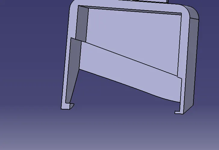
Step 12: Apply fillets and drafts at inner and outer faces according to respective tooling and lifter direction .
Procedure to create 4 way locator .
Step 1: Insert a geometrical set and name it as screw boss . Use reference point from tooling axis as projection point and xz plane as reference plane.
Step 2: Create an iso constrained positioned sketch with 2 perpendicular lines about origin of the sketch .
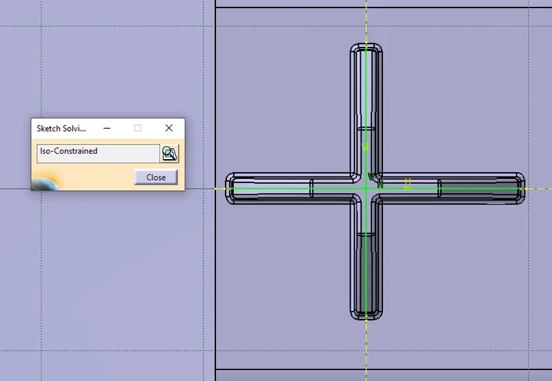
Step 3: Create a new body as screw boss and pad the above sketch with 1.5mm thickness and 20mm height.
Step 4: Apply draft and fillets at required regions and use boolean operation add to the dog house .
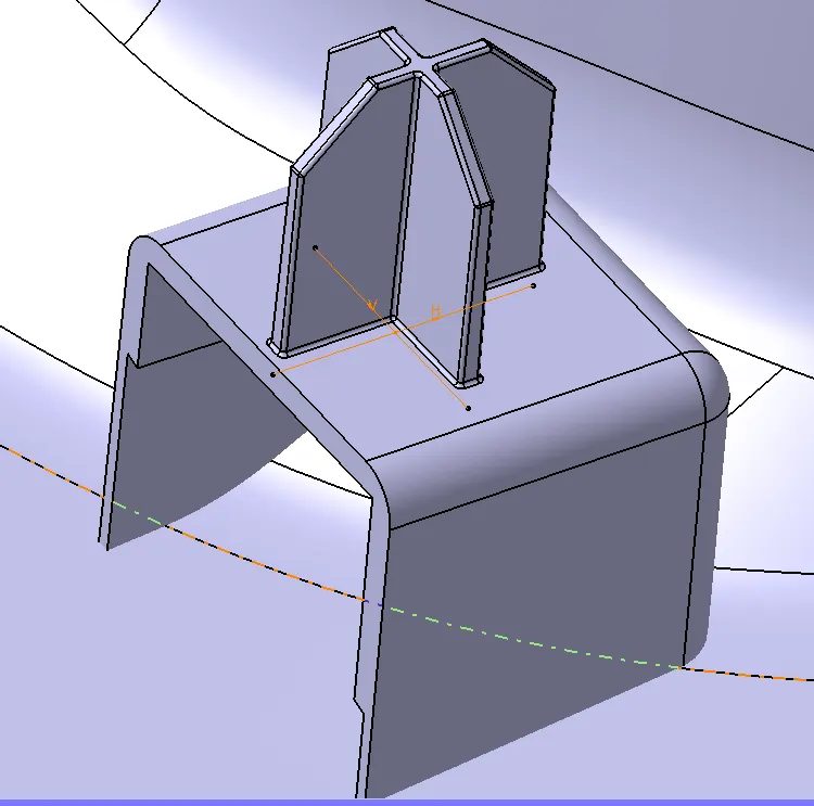
Thus we have created the 4 way locator as per the master section .
Use copy and paste special option to copy the 4 way locator and use symmetry option to position the copied body to opposite side.
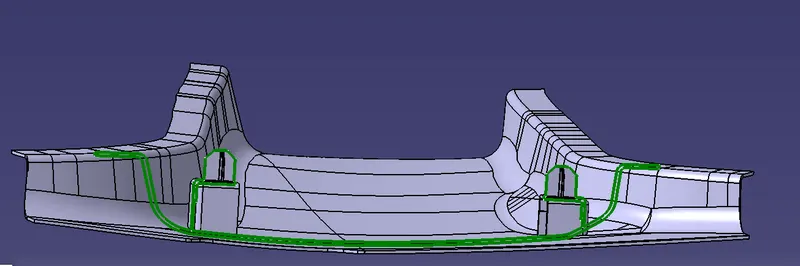
Procedure to create ribs
Step 1: Insert a new geometrical set and name it as rib parent .
Step 2: Create a positioned sketch with base point and reference plane as same as for locator .
Step 3: Create a line of 90 mm , minimum 60 mm from the horizontal axis of the sketch . Iso constrain the sketch .
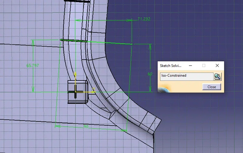
Step 4: Use extrude command to extend it below the Class A surface .
Step 5: Create a new body and name it as rib parent .
Step 6: use pad option to create a solid and assign a thickness of 1.2 mm .
Step 7: Use pattern along a reference plane to create multiple ribs 50mm apart .
Step 8: Offset b surface 10 mm value .
Step 9: Split the patterned solids using above offset .
Step 10 : Apply draft and fillets at required areas .
Step 11: Repeat above steps to obtain ribs at left side as well .
Step 12: Union trim both the bodies with main solid to obtain required component .
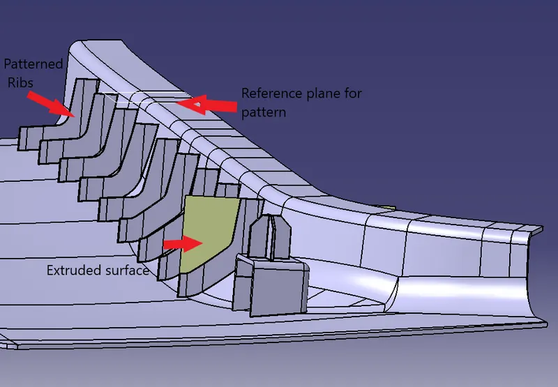
Final Body
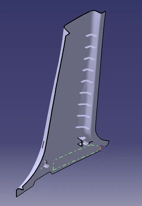
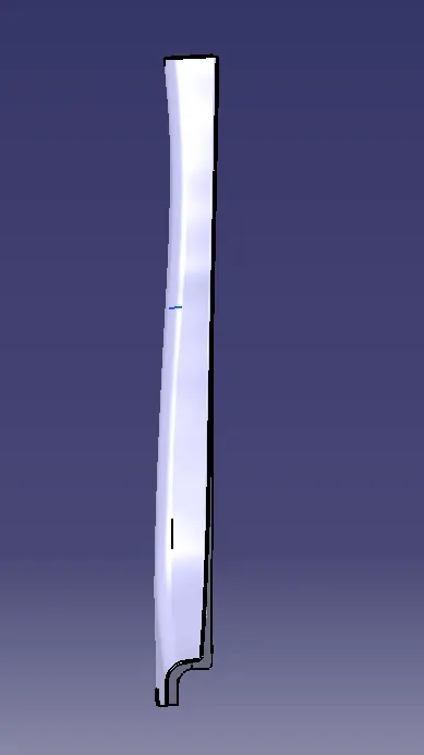
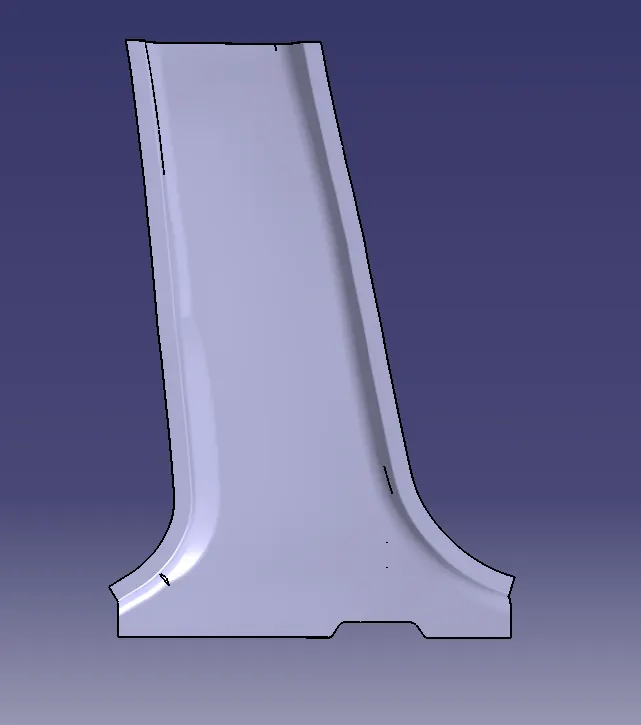
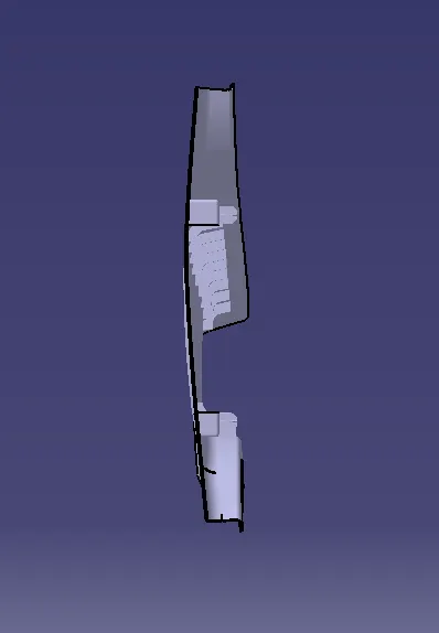
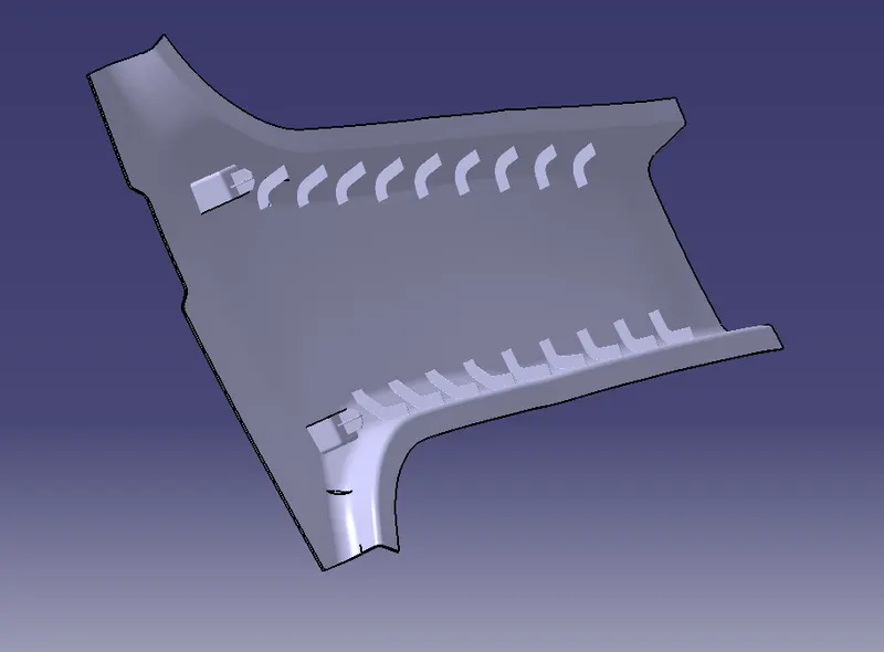
Draft Analysis Images
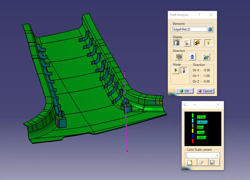
Draft Analysis for lifter axis