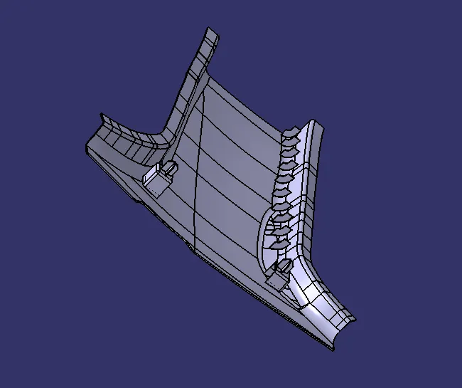
B-Pillar Design From Master Section
B-PILLAR DESIGN FROM MASTER SECTION
CLASS A SURFACE QUALITY IMPROVEMENT:
- For the start, we must check the given input class A surface for errors or bad quality patches. Then solve them to get a good quality class A surface to go ahead with the design process.
- As the given surface had some improper edges, I have corrected them and some other patches to get the following improved class A surface.
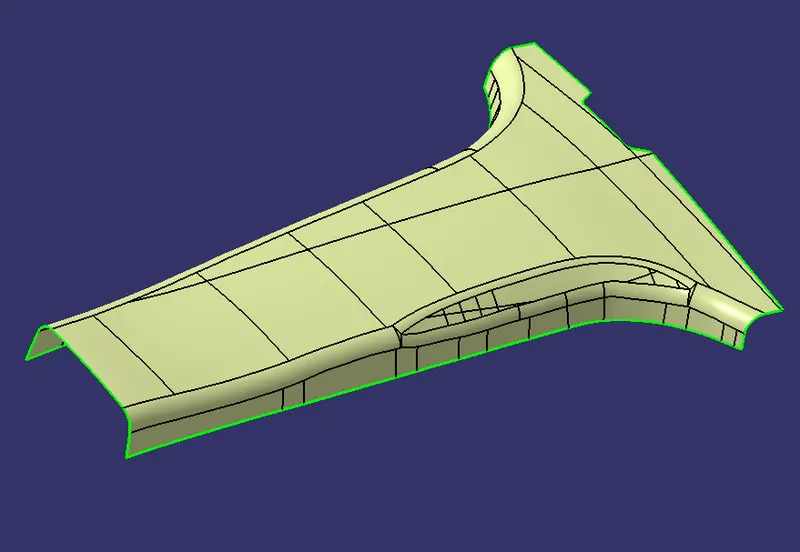
- Then we move ahead to develop the flanges that are shown in the given master section as shown below.
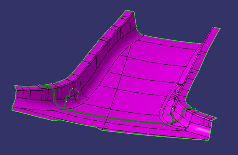
CREATING TOOLING AXIS:
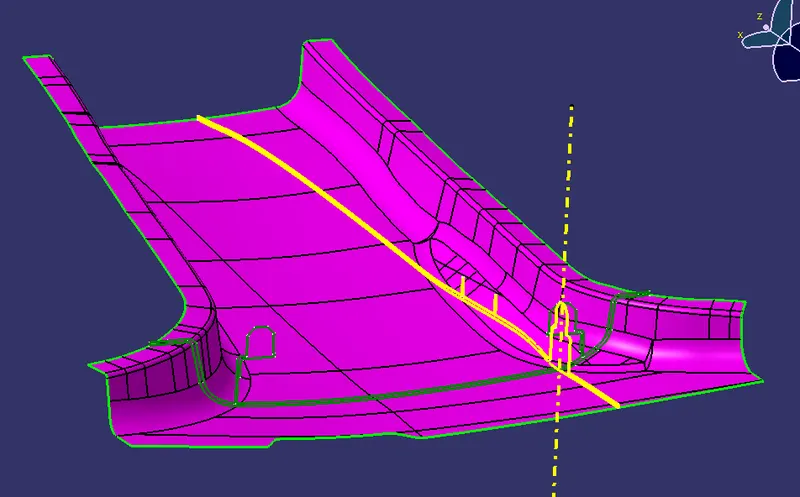
- For obtaining the tooling direction, we can use the vertical lines along the locator part as shown below from the master sections provided.
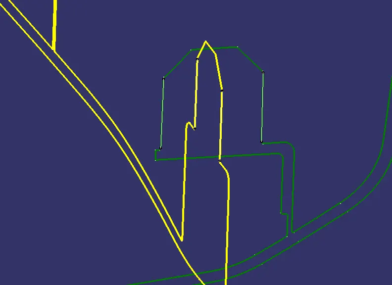
- Then we can get a line by bisecting these pair of lines, which can be our main tooling axis. For confirming we need to take draft analysis of the improved class A surface.
- Here, it should be noted that the line obtained from above does not satisfy draft condition so we need to adjust the compass accordingly in ‘Draft Analysis’ and get the main tooling axis from there.
DESIGN METHODOLOGY:
Class B & C surfaces:
- After obtaining the tooling axis, develop the class B and class C surfaces with proper design regulations to get the enclosed surface body.
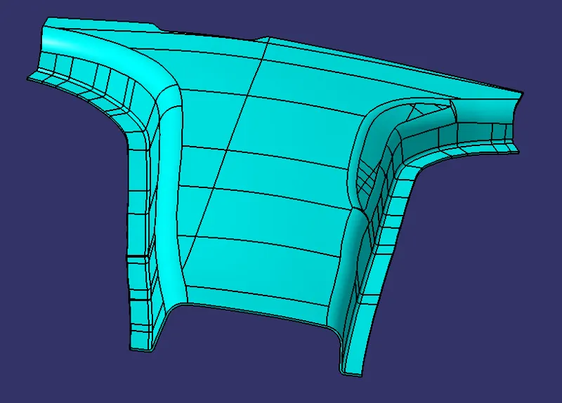
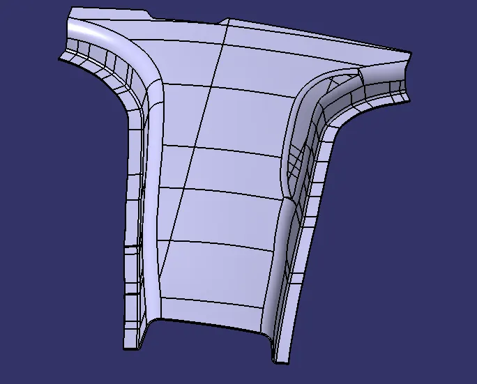
- Then get the solid body by using ‘Thick surface’ command.
Dog House:
- For dog house, we can use the given master section for reference.
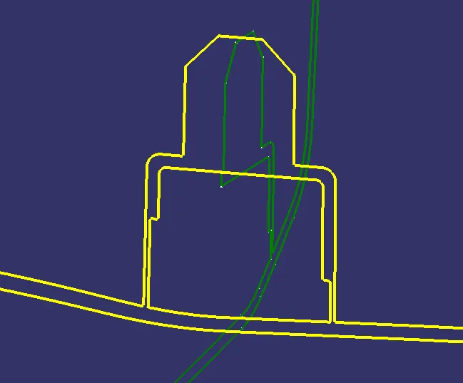
- We develop the dog house with regular design rules and dimension values.
- Below are the sketches from dog house 1 for vertical walls, front end and sketch for thinner wall trim correspondingly.
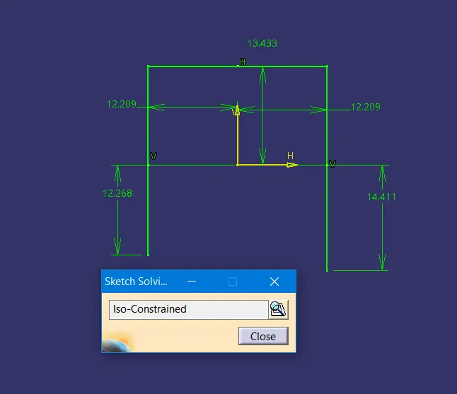
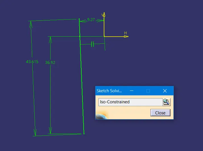
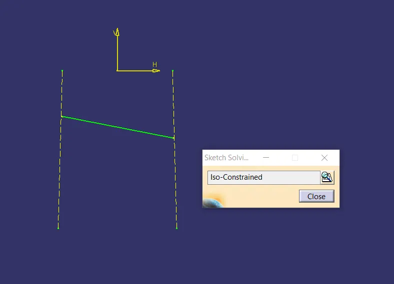
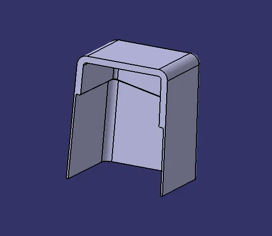
- Similarly, for the 2nd dog house, we use the master section as reference and develop the same.
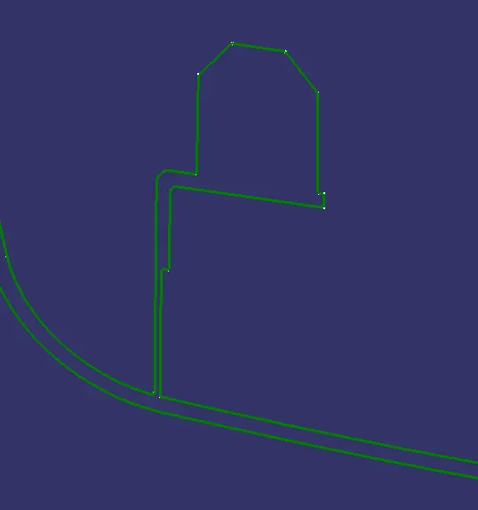
- Here are some of the sketches from dog house 2 for vertical walls and front end, and thinner wall trim correspondingly.
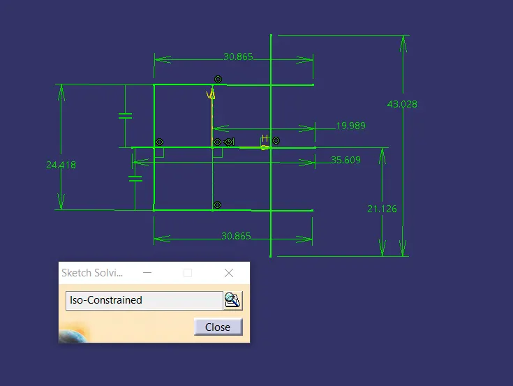
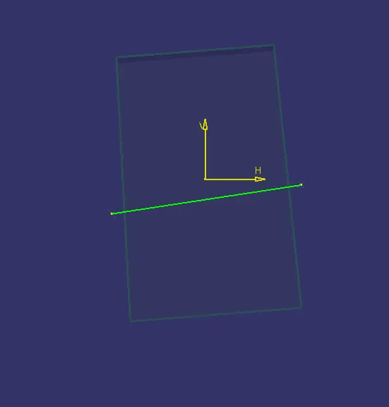
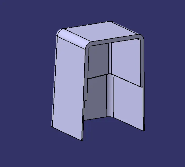
- We need to make sure that all the sweeps for vertical walls are done along the main tooling axis with and draft angle of 1.5 degrees at least, in order to get positive draft.
- Further, draft analysis results for both are shown in the images section.
4 Way Locators:
- After that we need to create locators.
- For the 1st locator we can take the top of dog house 1 as a base reference.
- We can also use the master section provided for reference.
- Then take a sketch as shown below.
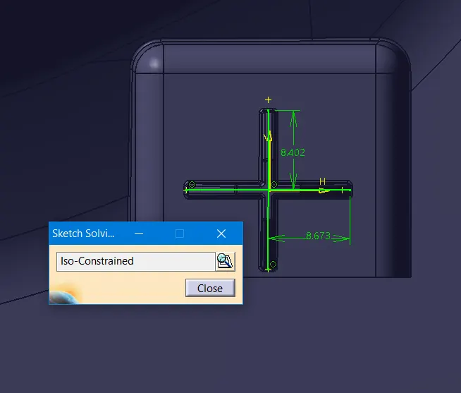
- After that, extrude the sketch for proper length using Pad command and thicken it by 1.5 mm. Make sure the pad is along tooling axis direction.
- Then apply chamfer and draft to vertical walls with a draft angle of 0.5 degrees along the tooling axis.
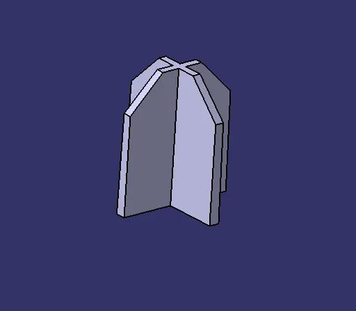
- After that you may add the locator to the dog house 1 body using proper boolean operation.
- Then add both the parts to main body using ‘Union Trim’ boolean operation.
- After that you can apply fillets to all edges.
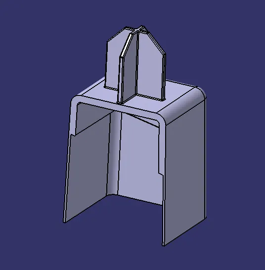
- Further, for 2nd locator take a sketch on the plane along top of dog house 2 and draw as shown below with the use of references from the given master section.
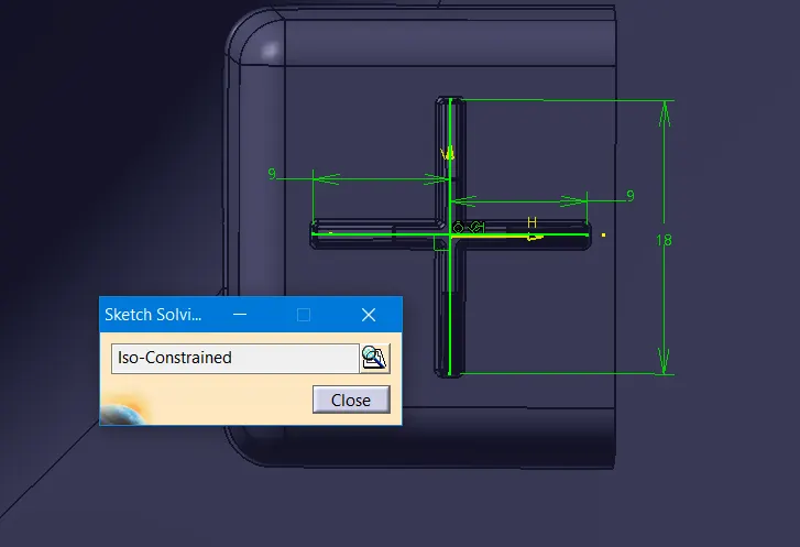
- Then extrude for appropriate length using Pad command and thicken by 1.5 mm.
- Add drafts to vertical walls with draft angle of 0.5 degrees and then add chamfer.
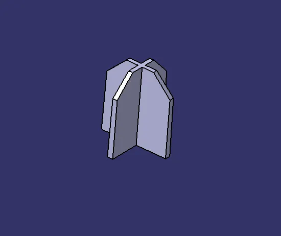
- Then add the body to dog house 2 using proper boolean operation.
- After that you can add fillets to edges.
- Then you can add the entire body to main sold body using union trim boolean operation.
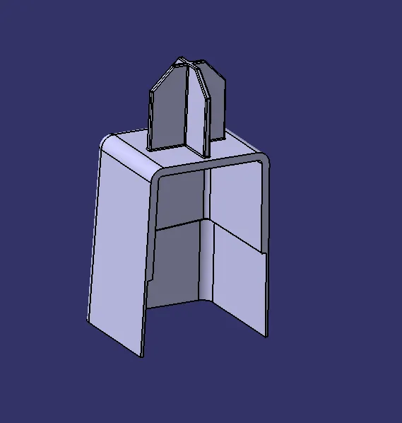
- The draft analysis results for the locators are shown in the images section.
Rib Design:
- For rib design, start by taking a sketch along a plane along tooling axis and draw using the master section references as shown below.
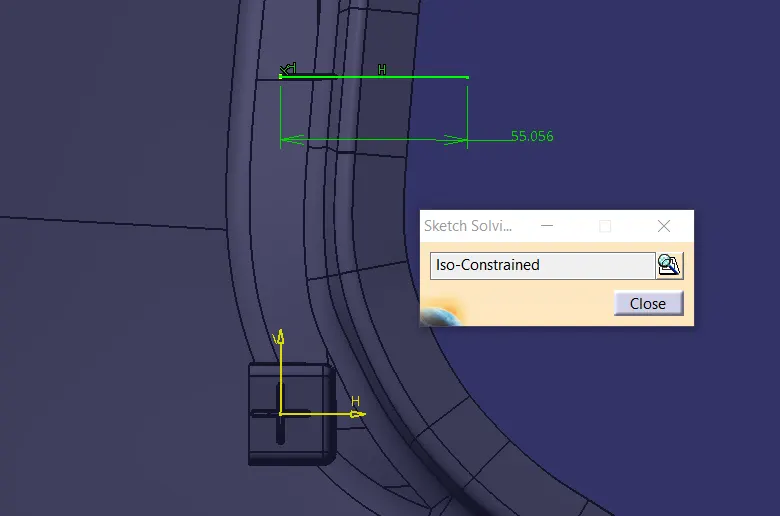
- Then extrude and thicken the rib with proper dimensions.
- Then provide draft to vertical walls along tooling axis with minimum angle of degrees.
- Further, to get multiple ribs we extract an edge on the body surface and use points repetition and copy paste method.
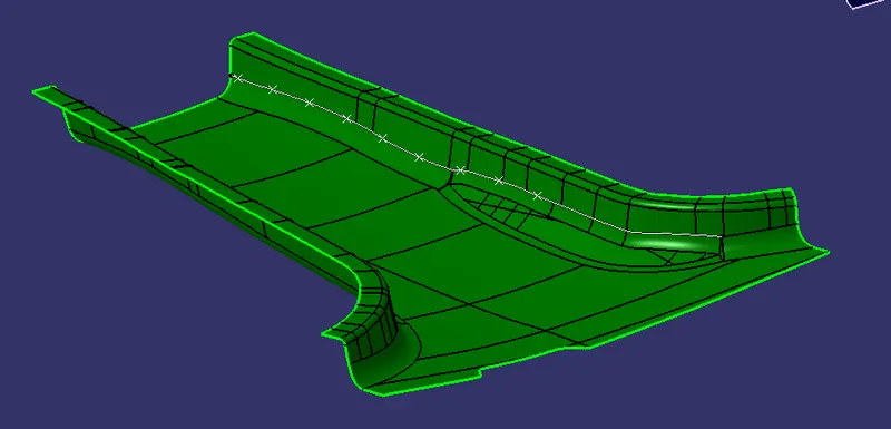
- We need to make sure that the distance between the 2 consecutive points is 50 mm.
- Then we can copy and paste the solid rib body and translate it to the corresponding point using ‘point to point’ translate option.
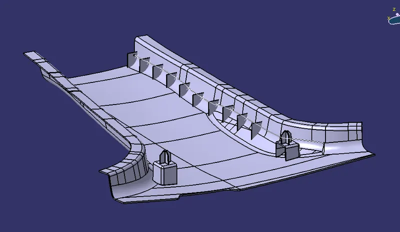
- Then we need to split the top portion of all the ribs by offsetting the corresponding class B surfaces in order to maintain uniform rib height.
- After that we can add the body with all the ribs to main solid body and add proper fillets to edges.
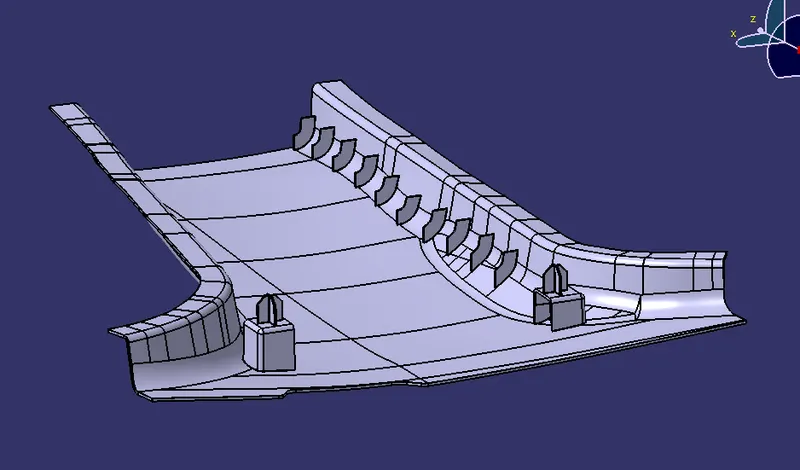
- Draft analysis results for ribs are given in images section.
IMAGES
DRAFT ANALYSIS AND COLOR SCALE VARIANT
Class A Surface
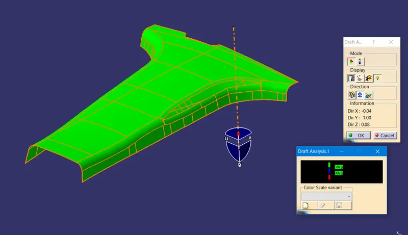
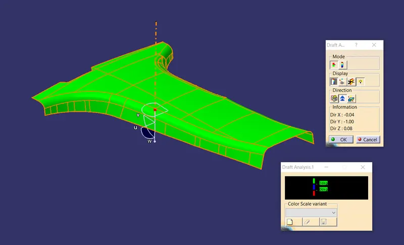
Surface Body (Without dog houses, locators and ribs)
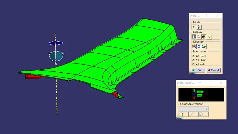
As you can see surface body is cleared in draft analysis at 2.7 degrees.
Solid Body (Without dog houses, locators and ribs)
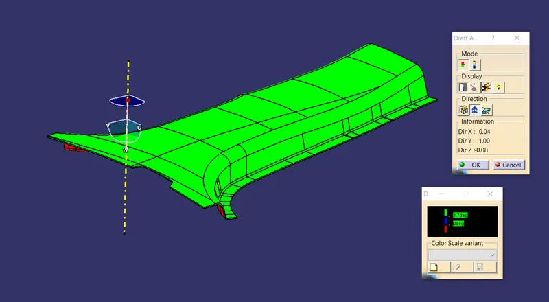
As you can see solid body is also cleared in draft analysis at 2.7 degrees.
Dog House 1 (along main tooling and lifter axis)
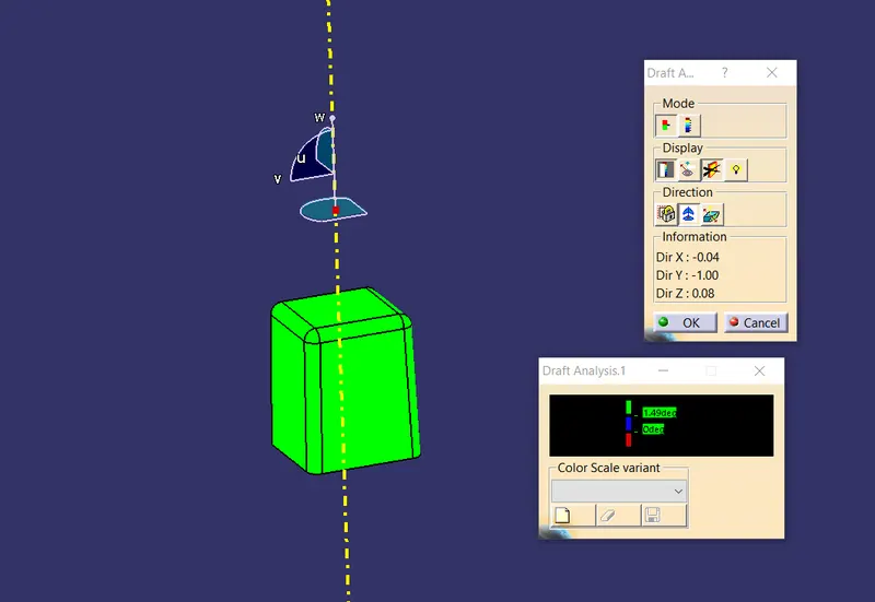
Dog house 1 has positive result in draft analysis along main tooling axis at 1.49 degrees.
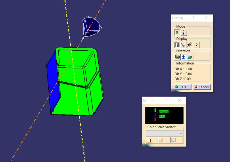
Dog house 1 has positive result in draft analysis along lifter axis at 0.48 degrees.
Dog House 2 (along main tooling and lifter axis)
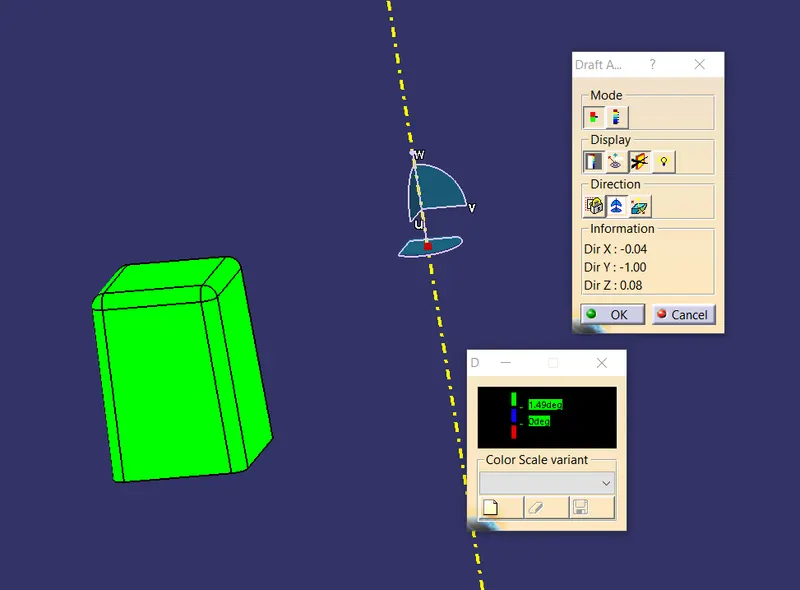
Dog house 2 has positive result in draft analysis along main tooling axis at 1.49 degrees.
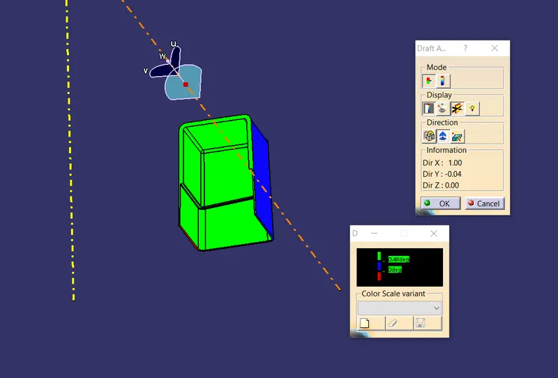
Dog house 2 has positive result in draft analysis along lifter axis at 0.48 degrees.
4 Way Locator 1
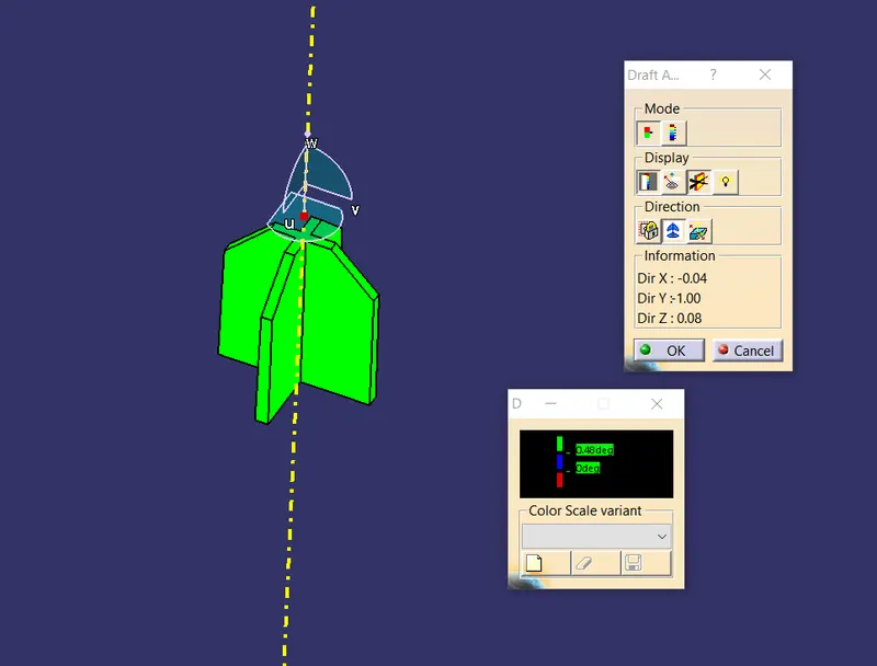
Locator 1 has positive result in draft analysis along main tooling axis at 0.48 degrees.
4 Way Locator 2
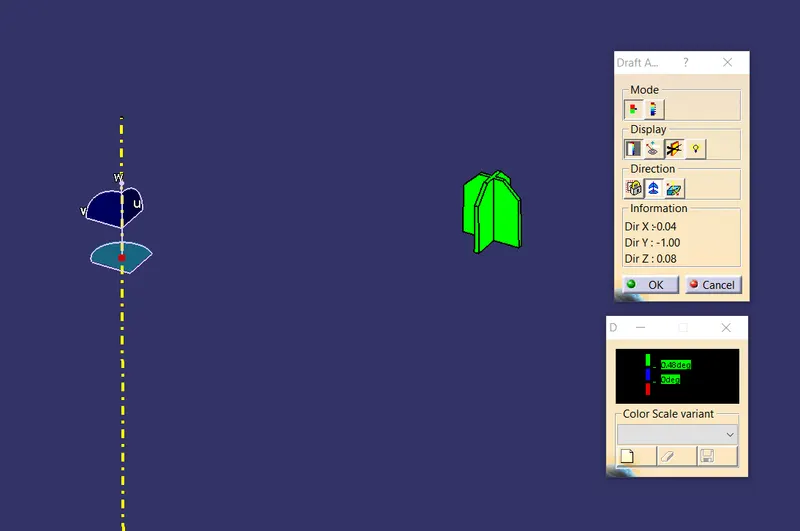
Locator 2 also has positive result in draft analysis along main tooling axis at 0.48 degrees.
Ribs
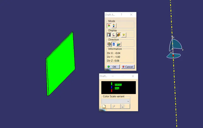
As you can see, rib gives positive draft result at 0.48 degrees. It should be noted that all the ribs will have same results in this case as they are translated using point to point translation.
Final B-Pillar Body
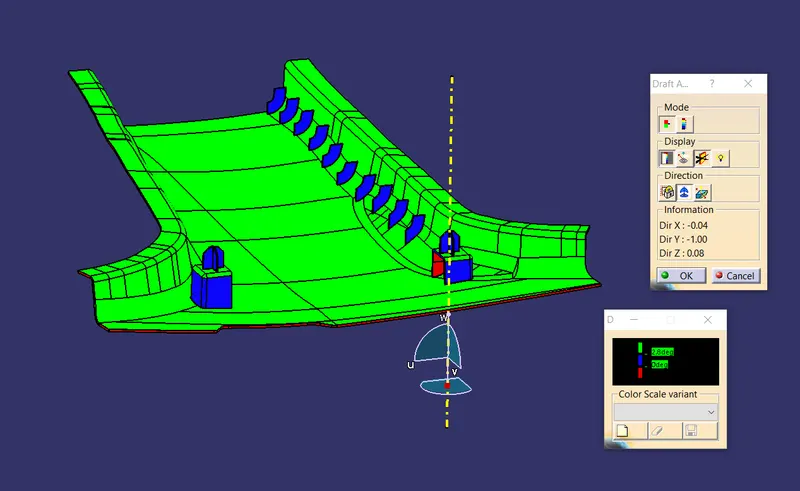
Final B-Pillar solid body has positive result along main tooling axis at 2.8 degrees.
MODEL DIFFERENT VIEWS
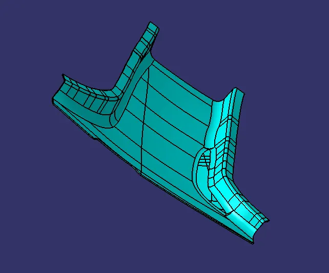
Surface Body (Without dog houses, locators and ribs)
Front view
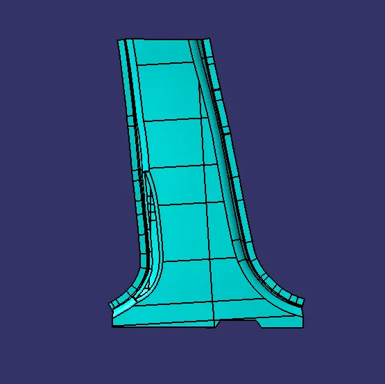
Side view
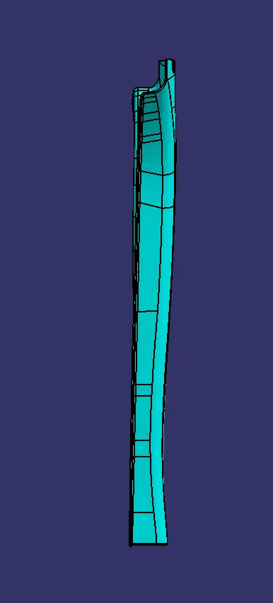
Top view
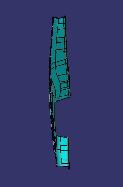
Isometric view
B-Pillar Final Solid Body
Front view
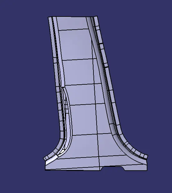
Rear view
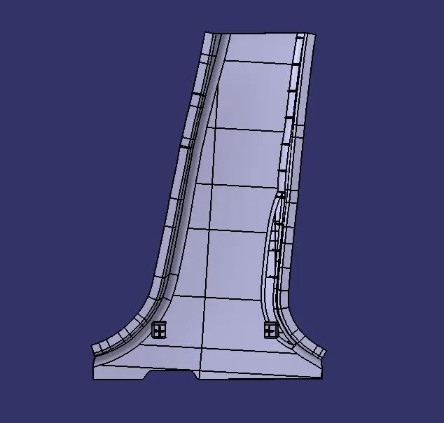
Side view
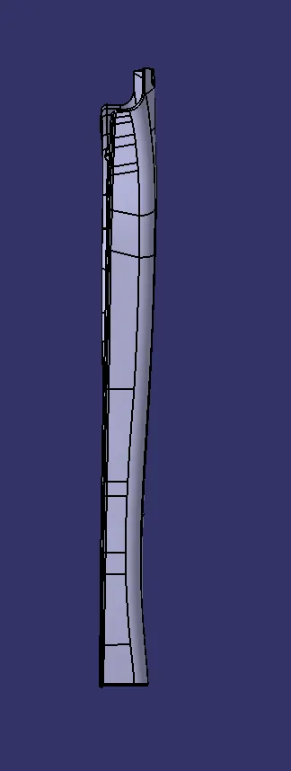
Top view
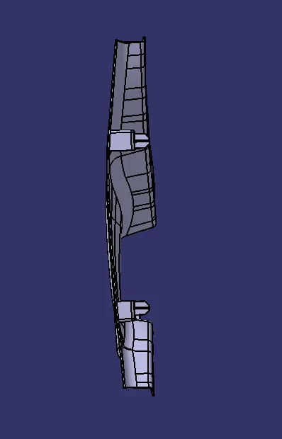
Isometric view