Week 9 - Project - Master Section Development
Master Section Development- B pillar solid part
Objectives:
- To make solid model out of a class A surface using surface commands
- To create diffrent attachment features on the class B side referring to the master sections
- To analyze the component for draft angles
- To make a presentation of the draft analysis report.
Introduction:
For an enginner to work on a OEM standard product design, It is important to convey the proper input ideas in a concept state. The part where a CAD designer get's involved is usually after specifying the surface features and internal attachment features. So the required B surface features needs to be marked at proper areas before starting the CAD design. For that purpose, we use the Master sections. A designer can get the required dimensions and positions of features by referring the master sections.
In this project, it involves The complete procedure of A product design from Class A and master sections as input and the final draft analysis report as output.
Design methodology:
Input class A surface:
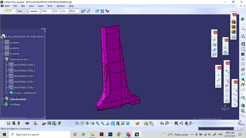
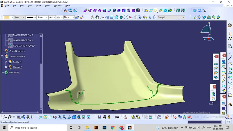
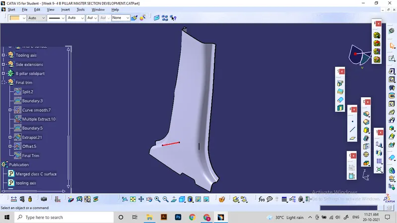
According to the master sections given, It needs some extra features like flanges on both sides. It's done using drafts on smooth curves.
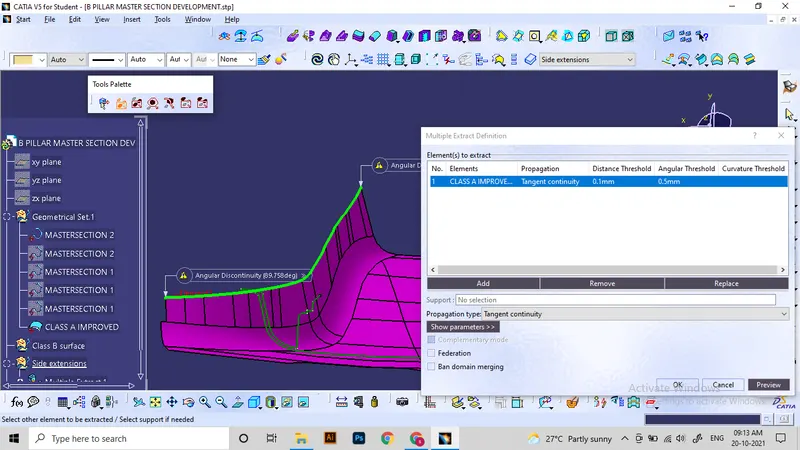
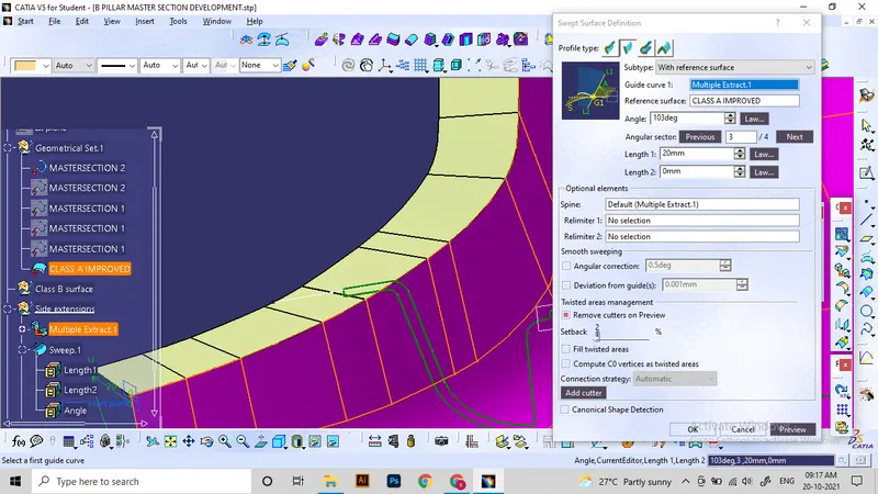
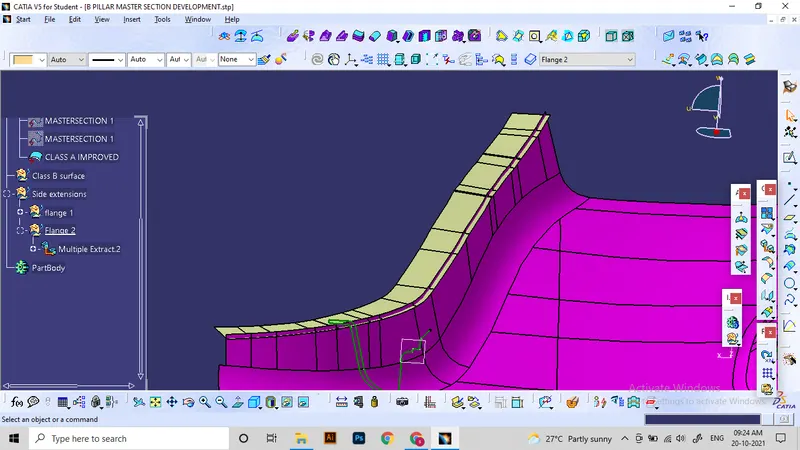
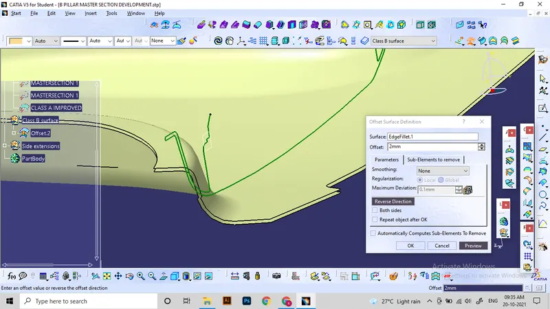
In this case class B surface can be made using offseting from class A. At a thickness of 2 mm.
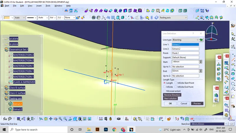
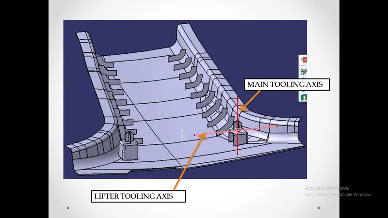
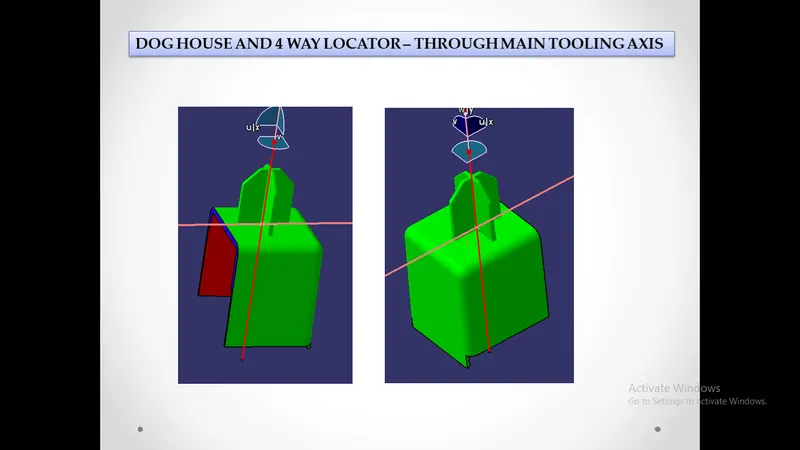
To make the class C surfaces, We need the tooling axis. It can be made by taking references from the master sections. Main tooling axis is made by bisecting 2 outer lines taken from master sections. and side tooling axis is perpendicular to the inside surface of dog house feature.
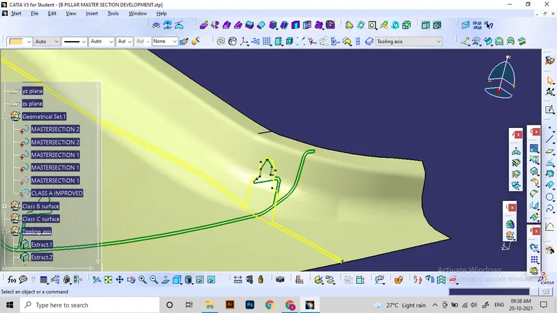
Use side surface boundaries to make Class C surfaces
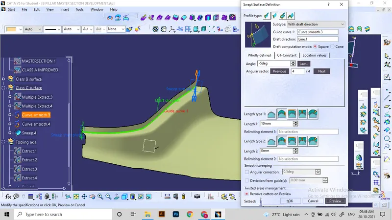
Some edges have non-continoutinuities and other errors in line flow, These are fixed by introducing new surfaces to those areas and splitting the class A making new continous surface boundaries.
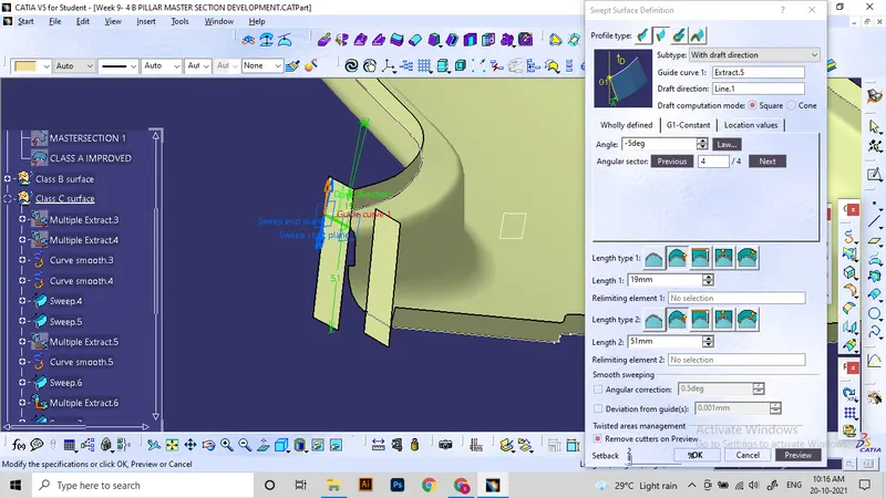
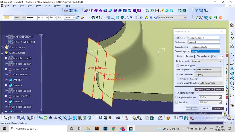
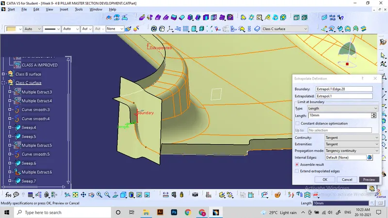
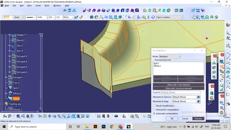
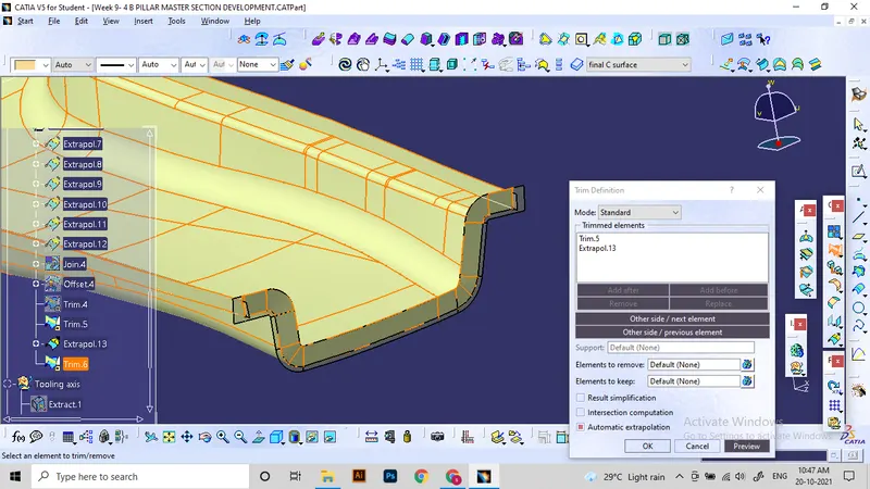
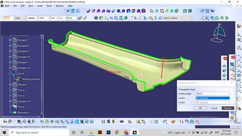
Later the 3 surfaces are trimmed together and Used close surface to make solid part.
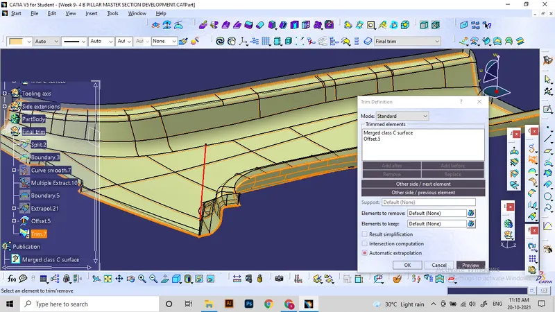
Class B side features:
According to the master sections, It needs two number of 4 way locators placed above Dog houses.
For dimensions, taking references and extracting lines and sketches from master sections.
The initial plane structure is made using shape design workbench and Solidification in part workbench.
Each features are made as individual solid parts which are then will be added or union trimmed with it's base part.
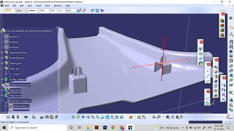
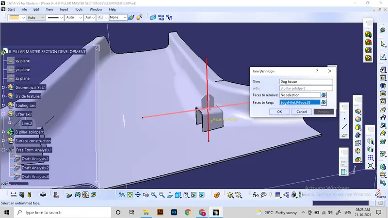
Dog house:
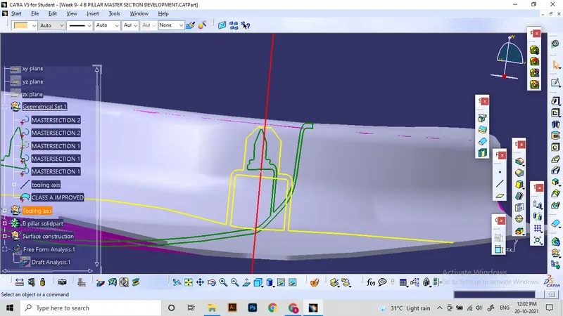
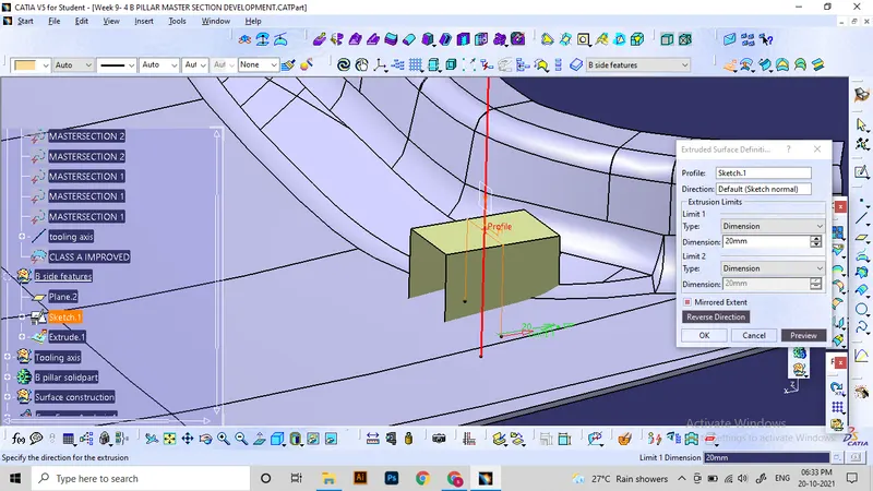
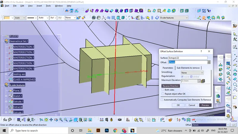
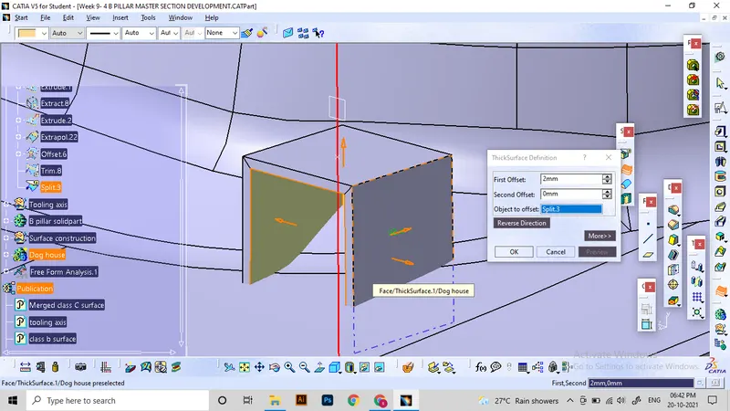
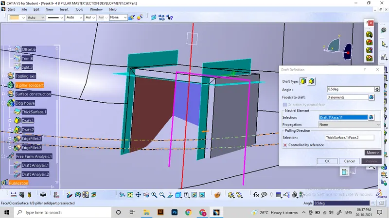
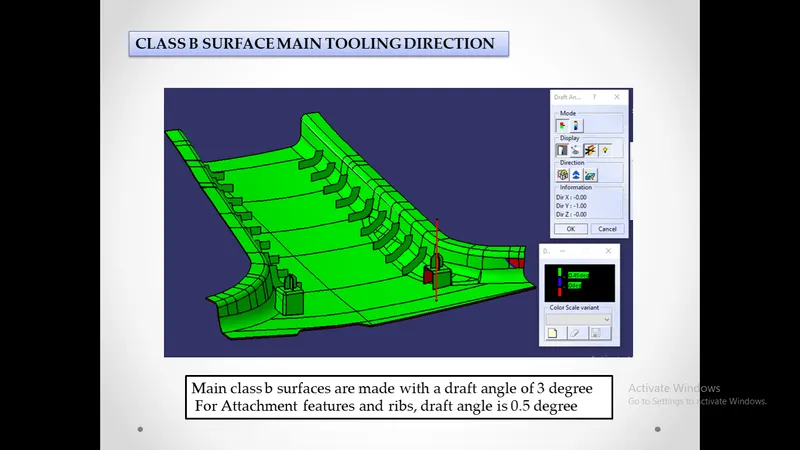
Drafts for B side features are taken as 0.5 degree to the main tooling axis.
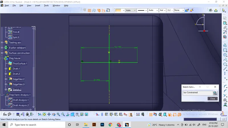
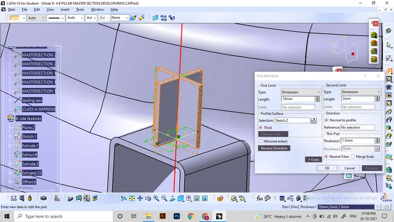
4 way locator:
The top surface of dog house is taken as the base for sketching the lines for 4 way locator:
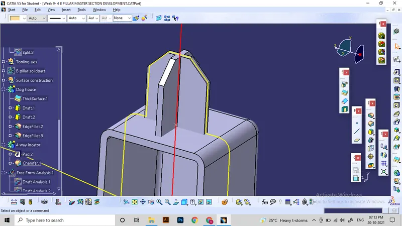
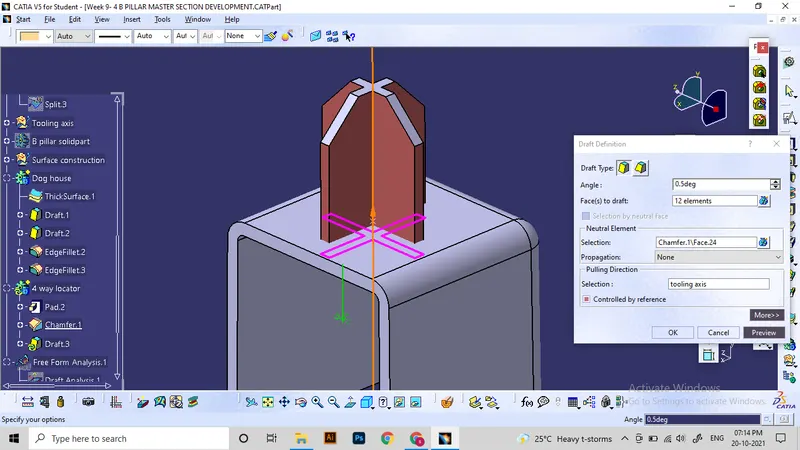
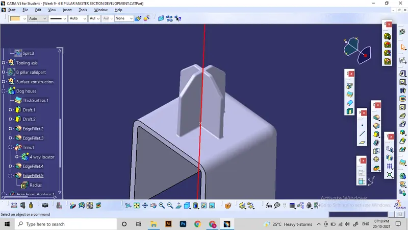
Lower part of the Dog house needs to reduce the thickness for avoiding sink marks.
Thickness for this area is 0.4 times the thickness of part. ie, 0.8 mm.
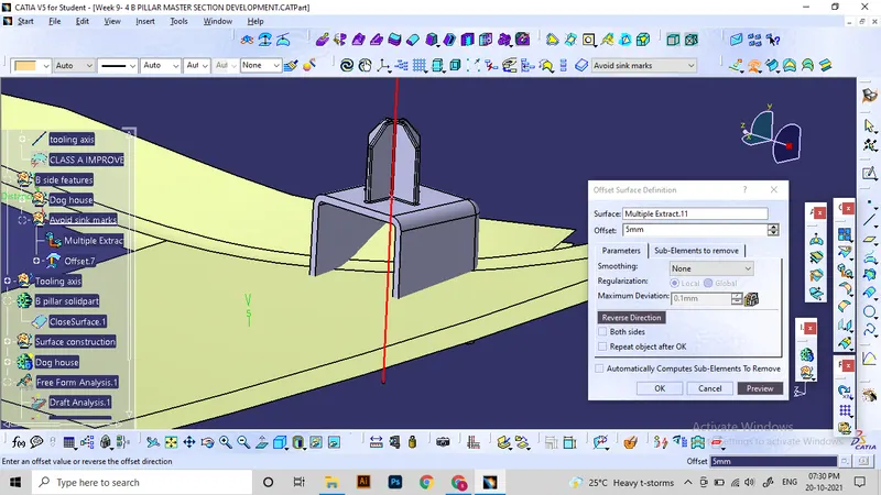
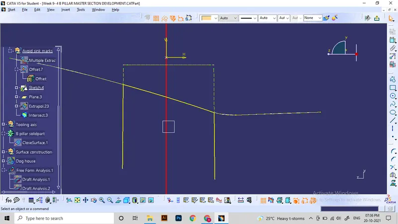
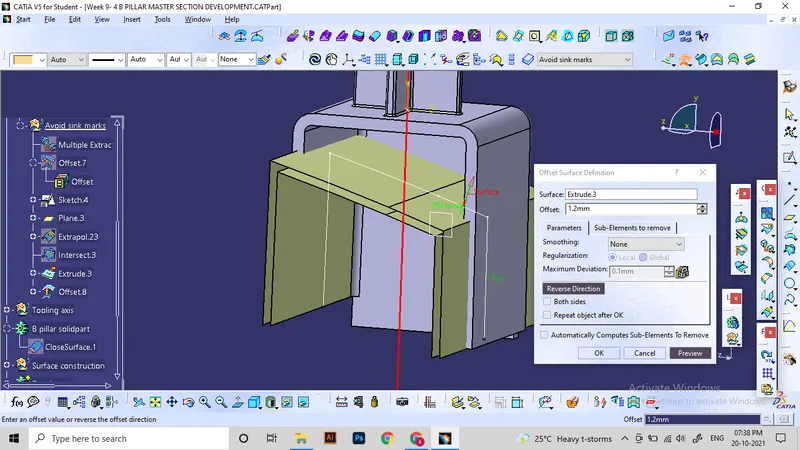
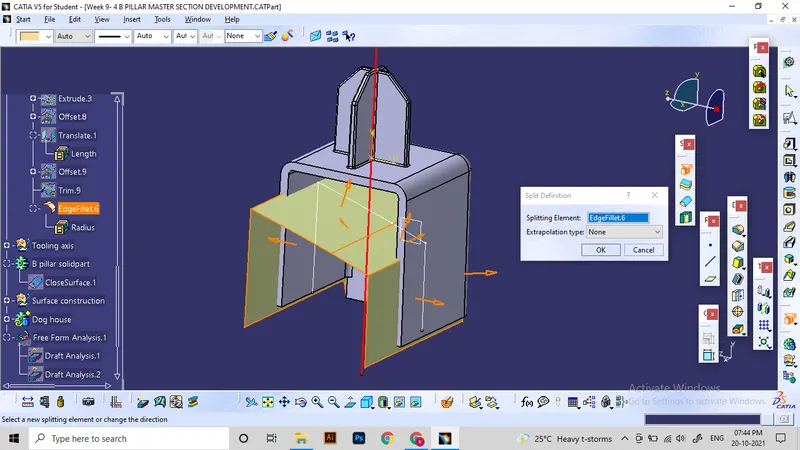
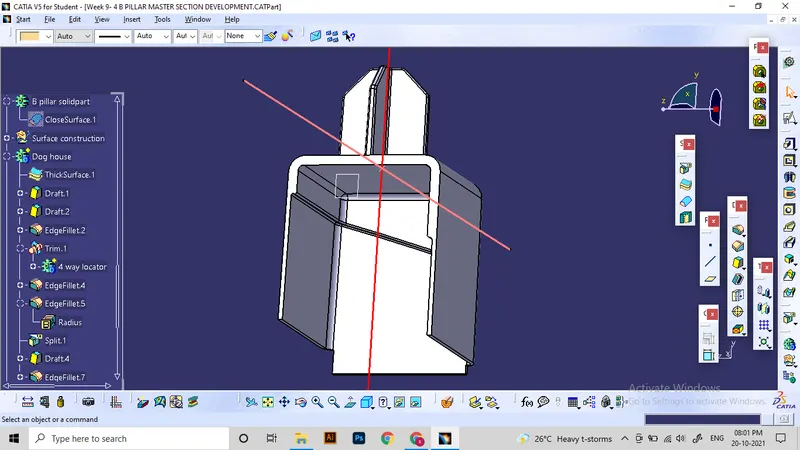
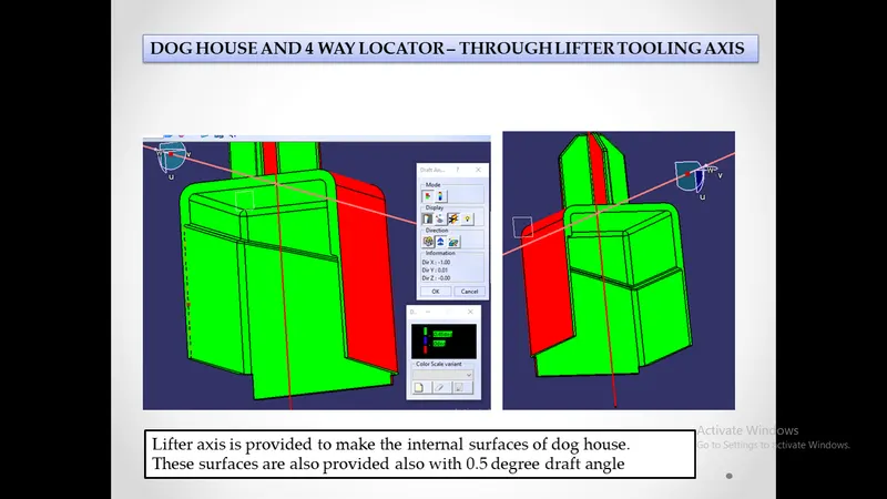
For the inside features of dog house, A tooling axis known as lifter axis is provided. It is used to specify areas for Lifter cores, and to draft the inside surfaces.
Later, symmetry this element to the next position. and union trim both with the B pillar solid part.
Ribs:
These are made for giving strength to the surfaces.
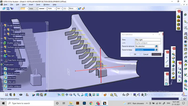
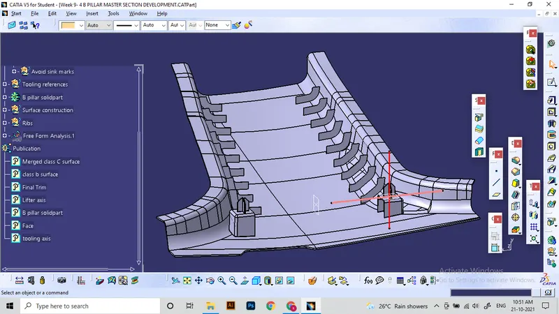
Ribs are made in a series form at required locations as shown.
Thickness is taken as 0.8 mm for each rib. which are placed at a distance of 50mm from each other.
Other dimensions assumed as it fulfills it's function
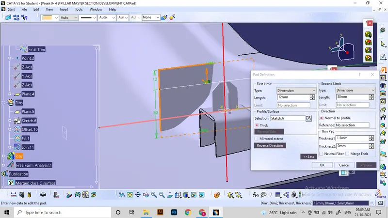
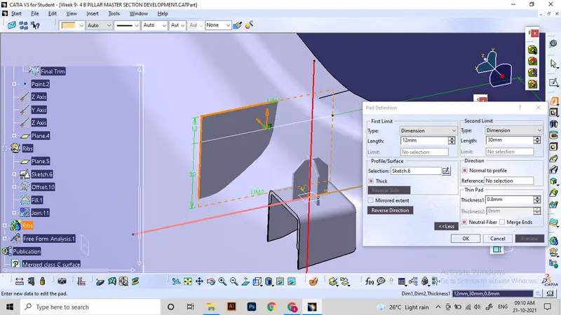
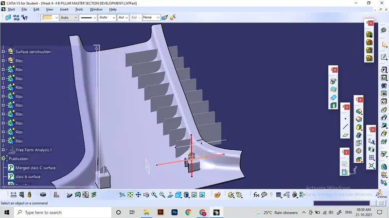
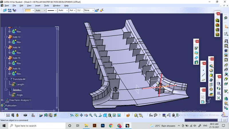
The inner side of ribs are splitted using a surface offseted from class B surface at 10 mm distance.
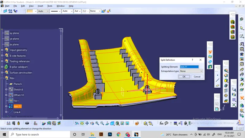
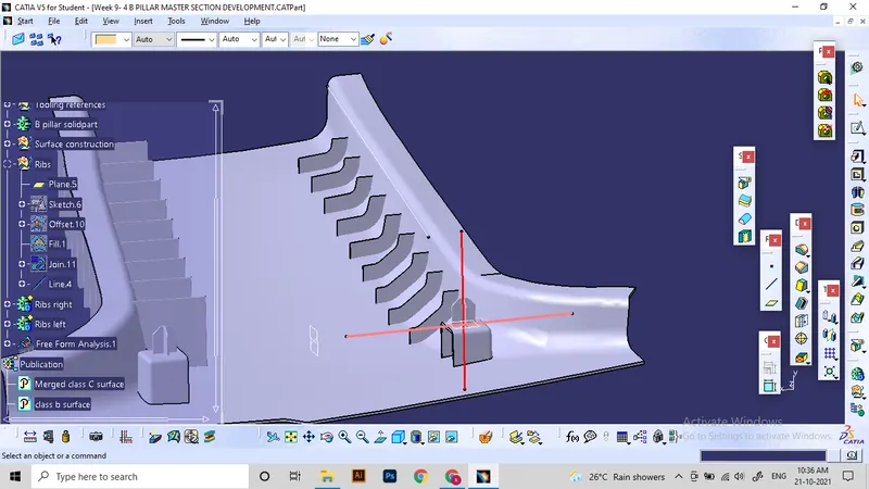
These are union trimmed with main part body. Later did the same for the next set of ribs.
Draft analysis report:
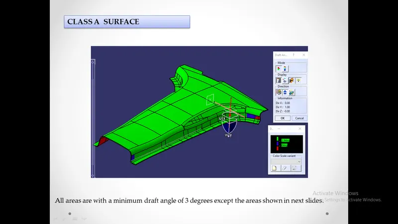
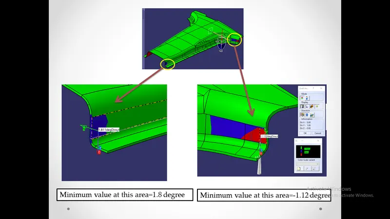
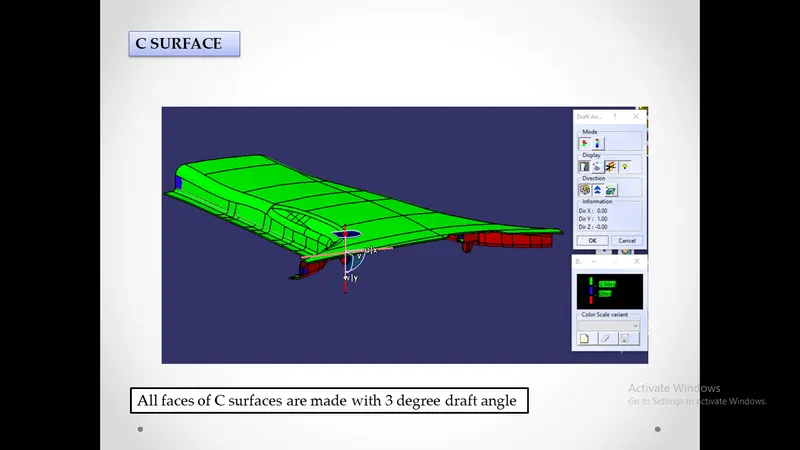
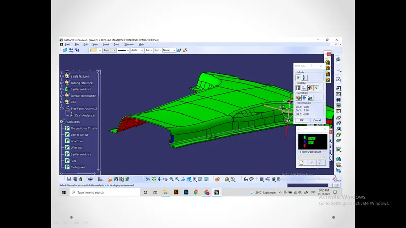
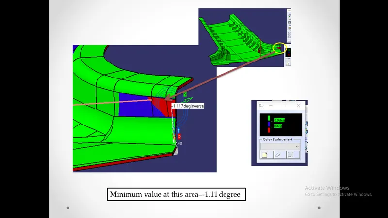
- Tool used: Feature draft analysis
- Surface draft angle Class A and Class C sides: 3 degree from main tooling axis
- Draft angle for class B features: 0.5 degree from main tooling axis and lifter axis.
- Report submitted as Presentation file along with this document.
Results:
- All required geometrical elements acording to the given instructions are made with maximum accuracy.
- Surface formation errors and dicontinuities are cleared and currected.
- Draft analysis is conducted for diffrent elements and surface draft angles are measured.
- Provided instructions for manufacturing procedures like the arrangements of tooling axes.
- Errors are analysed and marked for later assessment.