Week 9 - Project - Master Section Development
Aim - To create the B piller component through the given master section and class A surface, and attach B side attachment features like dog house and 4 way locator.
procedure -
Developement of Class A Surface-
- from the given class A surface first we need to see there are any errors like patches, double boundaries, irregurlar surfaces etc...
- to rectify these kind of errors we need to use boundary tool to see there are any unwanted boundaries and hence if there we need to clear them.
- hence the surface is cleened up we need to extract the given class a surface by using offeset tool. here we need to offset with out giving the any distance and hide the original class A surface.
- now from the master section 2 we observe that we need to there is a flange which is a engineering feature.
- to create the flange we need to extract the side boundary of the class a surface then we need to extract the adjacent side after the extract is taken we need to use sweep tool (with reference surface), by using this tool we will get the flang surface. note we have to choose the correct angle with the help of the master section 2.
- since we get the flange for one side there for we need to follw the same procedure to the other side also. after getting the two flanges we need to combine them with the class A surface. by doing this we will get class A surface for the B-piller.
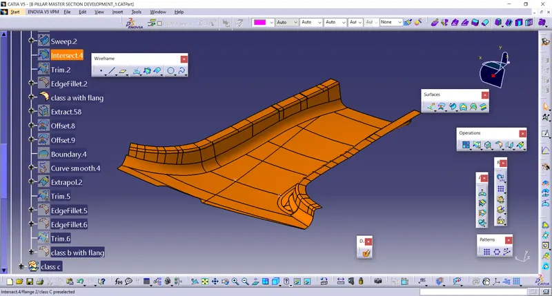
Image showing the developement of class a surface-
Before-
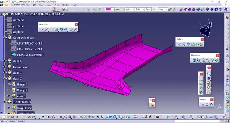
Class A after
Creation of Class B Surface -
- For the creation of the class b surface we are going to use the class A surface which we developed, now we are going to use the off-set tool then we have to give the distance from which we need to get the off-set from the class a surface, to find the distance we need to measure the distance in the master section 2.
- After giving the distance we need to give the direction to the off-set(we haveto give the direction towards in side).
- Since the off-set towards the inside is done, because of the compressionof the surface takes place there will be missing of some surfaces we need to re-create these surfaces with the help of the tools like extract,spline,fill and multi-section solid. there by the class b surface is created.
- Then we need to extend the boundaries of the class b surface by using the extrapolate tool.
Off-set Class B surface before -
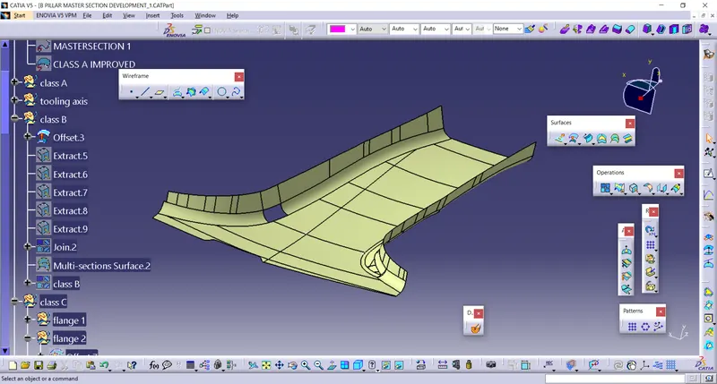
Off-set Class B surface after -
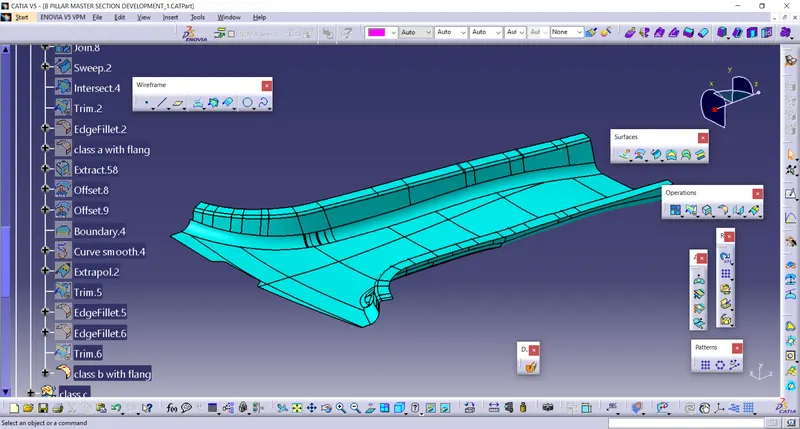
Creation of Class C Surface and converting it into solid -
- For the creation of class c surface we need to use class a boundary.
- After getting the boundary we need to use the sweep tool to get the class c surface. in the sweep tool (with reference surface), by using this tool we will get the class c surface. for the reference surface we need to give the class A surface as the reference surface then for the angle we need to give the angle fo the master section 2.
- we need to sweep the boundary one by one and final we need to combine them with trim tool. hence we get the class c surface.
- After getting the three surfaces we need to combine them with trim tool.
- Now we have to go to the apart worke bench and we have to use close solid tool to get a solid part.
Image showing the class c surface-
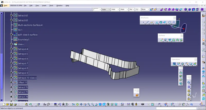
Combined image of the class A B C surfaces-
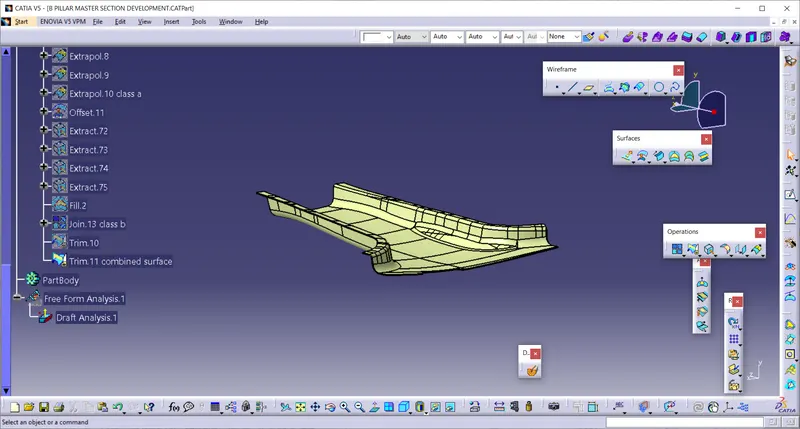
Solid B-piller image -
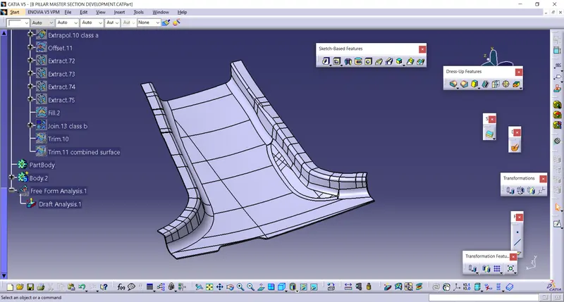
Creation of dog house and 4 way locator on the solid part-
- First we have to extract lines from the master section and with the help of extract tool and extrude them the help of extrude tool in generative shape design as per our requirement.
- now we have to go part design and use thicksurface to form a solid
- Now we have to add the dog house to the main part body , there fore we get a final body.
- General Guidelines for dog houses : minimum height should be 6.0 mm
minimum dog house width is 12 mm .
minimum draft for dog houes is 1.5 degrees
Doghouse wall thickness at the intersection of the part wall ( C ) should be 40% or less than the main wall stock ( T ).
Height of ( B ) should be between 3.0 – 6.0,where the B is the hight of the offesteed extrude and C is the wall thickness.
- General Guidelines for dog houses : minimum height should be 6.0 mm
Creation of 4 way locator -
- 1 For the creation of the locators we need to draw the shketch as of our requirement that is either +/-, + indicates four way locators and - indicates two way locators .
2 Now we need to take a plane and sketch the locators ,after editing the sketch we need to use the pad command in that we need to click the neutral fiber option for the correct ofset of the materials
3 Rules for creating a locators ------
Rib thickness at the tip = >=0.75
Rib Draft = >=0.5 degree
Rib radius(fillet) = 0.25 maximum
Rib Thickness (w) = 0.4*t (where t is thickiness of the wall)
Rib Root thickness = >=40% of wall thiskness
Rib depth or height = <=5t (where t is thickiness of the wall)
Rib spacing = 2t(where t is thickiness of the wall.
Image of dog housae and 4 way locator-
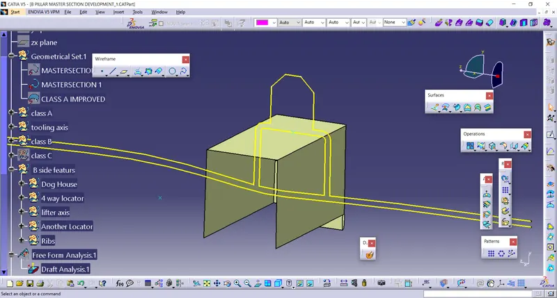
Image showing 4 way locator-
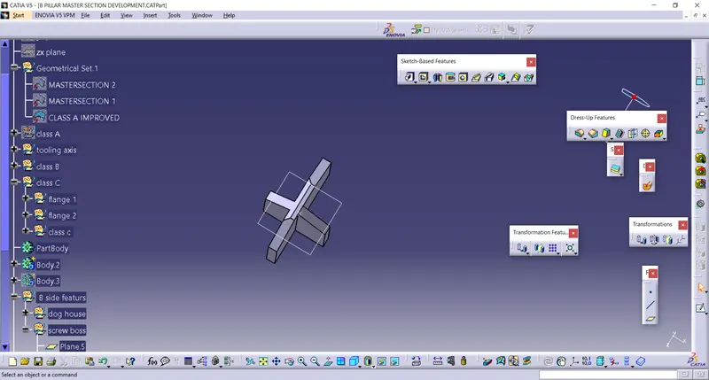
Creation of Ribs -
- First we need to select a plane and then we need to extract it .
- Next we need to open sketcher on that plane and we need to draw a lines and extrude them .
- After exrtuding we observe a plane , then we need to go to part body and then we need to use thick surface so that the solid surface is formed .
- Since the ribs are a different body we need to add to the main body so that we can use boolean commands and join them .after joining we need to give the fillets for the ribs .
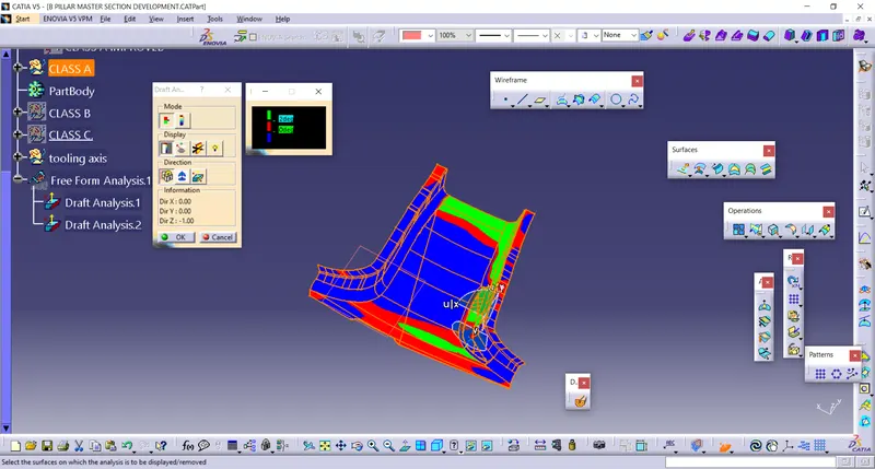
- And finally we need to do a draft analysis for these ribs .
- Rules for creating a rib ------
- Rib thickness at the tip = >=0.75
Rib Draft = >=0.5 degree
Rib radius(fillet) = 0.25 maximum
Rib Thickness (w) = 0.4*t (where t is thickiness of the wall)
Rib Root thickness = >=40% of wall thiskness
Rib depth or height = <=5t (where t is thickiness of the wall)
Rib spacing = 2t(where t is thickiness of the wall)
Draft analysis-
- Before starting to work on the part we have to see the connectivity of class A (the give input is closed or not )(use join)
- In order to creat a tooling axis we have to creat lines in x-direction and y-direction and we have to bisect them to get the tooling axis .
- We have to take the axis system at the center of the surface (calss A) and we have to intersect them with xz directon of the planes . so that we get wire frame in the desired
direction in which we have to creat lines and bisect them . so the lines we get after the bisection it is known as tooling axis .
we have to do this for the other direction (or )plane also . - After getting the tooling axis we need to publish them . (tools - publication - select on the requid elements).
- In order to do the draft analysis we need to change the material , which is present in . view tool bar . (view tool bar - cylinder - click the last cylinder) .
a window will open ,click on material then ok . - To open draft analysis , go to (insert - analyis - draft analysis )
- After opeaning the draft analysis tool
we have to click on the compass which is oresent in draft analysis table and find the compass , drag it towards the tooling axis and design them .
click on the lock box then ("x") thhis symbol will arise , go to the object and click on them .
we can measure the angle of object by clicking on the eye symbol which is present on the display .
we can get the result by clicking options which are present on the model .
Image showing rib sketch and ribs
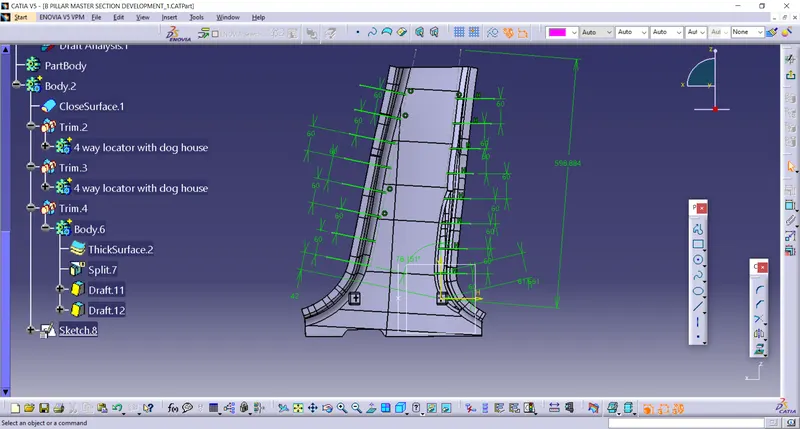
Image showing the draft analysis of the Class A B and C surface and full componenet.
Class A surface
Class B surface
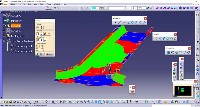
Image showing full Bpiller-
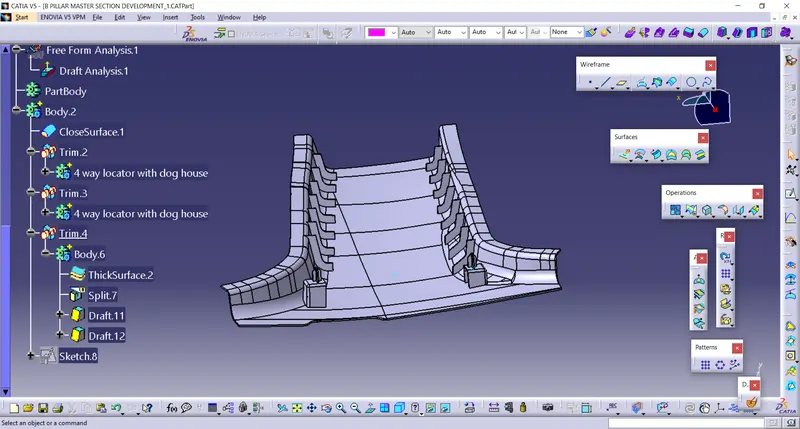
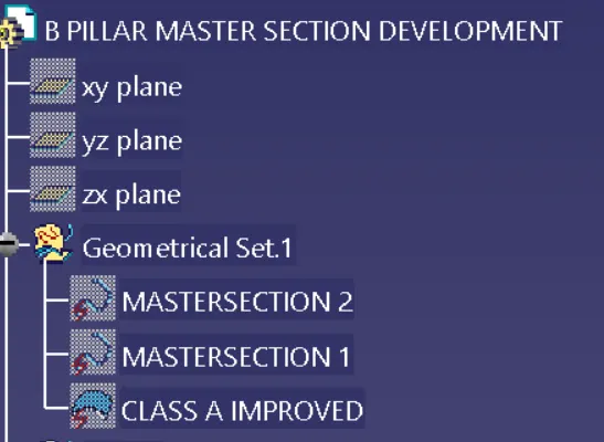
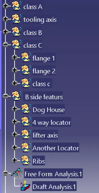
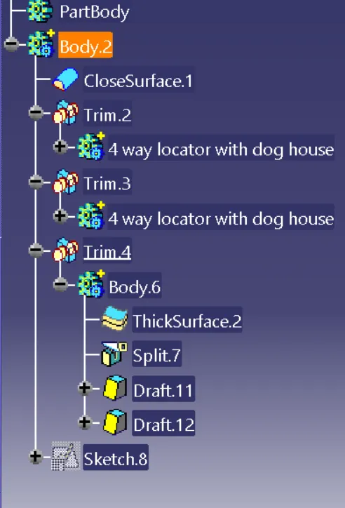
Tree Diagram Images -