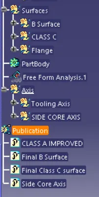
Week 9 - Project - Master Section Development
Master Section Development
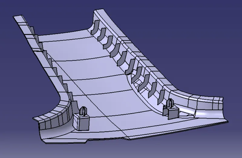
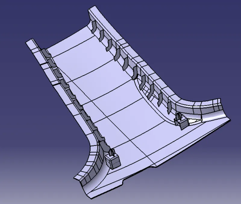
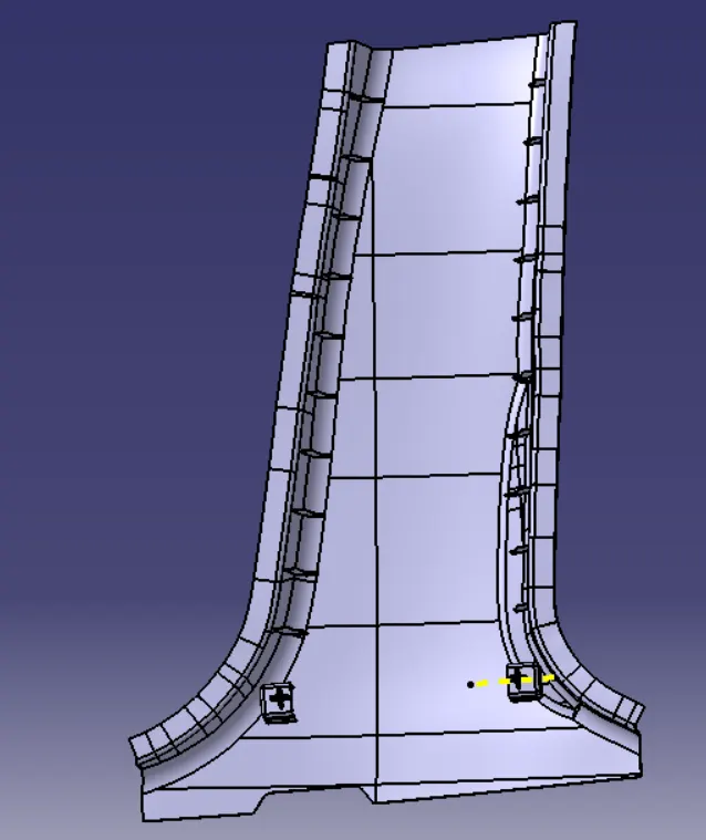
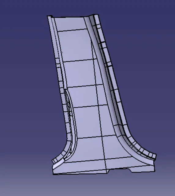
B Pillar
B Pillar is the most complex component/structure of the vehicle body. This is because the front door closes on the B pillar while the rear door hinges on it. The B pillar or the center pillar in vehicles is made of steel. It is welded to the roof panel on top and the vehicle’s floor pan at the bottom. This pillar provides structural support to the vehicle’s roof.

Draft Angle
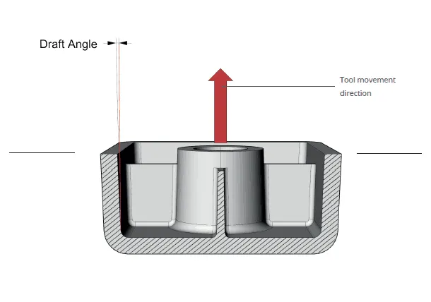
The draft angle is the amount of taper for molded or cast parts perpendicular to the parting line. It can be measured in degrees or mm/mm (in/in).
Tooling Direction
Tooling Direction is the main consideration for plastic parts and mold parts because it defines the movement of the mold part and the possibility of the part coming out from the mold part.
Tooling Axis
The axis along which the mold or core and cavity opens.
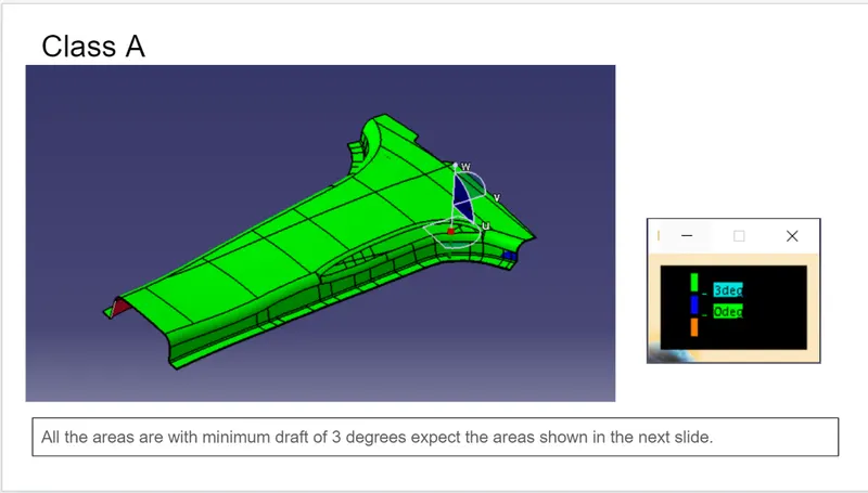
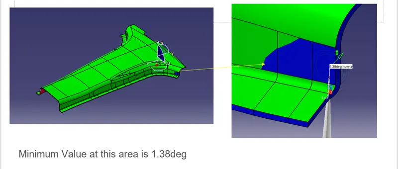
The draft analysis within CATIA V5 will help you quickly gather the draft angle on multiple surfaces without the need for tedious manual measurements. The Draft Analysis allows the user to easily analyze a part for proper draft angle.
Importance of Drafting
When developing parts for plastic injection molding, applying a draft (or a taper) to the faces of the part is critical to improving the moldability of your part. Without it, parts run the risk of poor cosmetic finishes and may bend, break, or warp due to molding stresses caused by the plastic cooling. Equally important, an absence of a draft may prevent parts from ejecting from the mold, damaging not only the parts but possibly the mold itself—a costly and time-consuming detour.
Mode Option
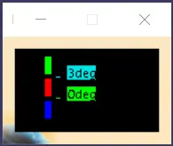
The mode option lets you choose between a quick and a full analysis mode. These two modes are completely independent.
The default mode is the quick mode. It simplifies the analysis in that it displays only three color ranges.
Class A Surface
- Visible surface and aesthetic look
- Surface with textures
- Surfaces provided by customer(OEM)
- Don't have any features like(rib, snap, bosses, etc) on class A surface.
- Class A surface is made from scanned data with different software like alias etc.
- Surfaces which is having CURVATURE CONTINUITY IS CALLED class-A.
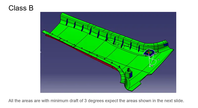
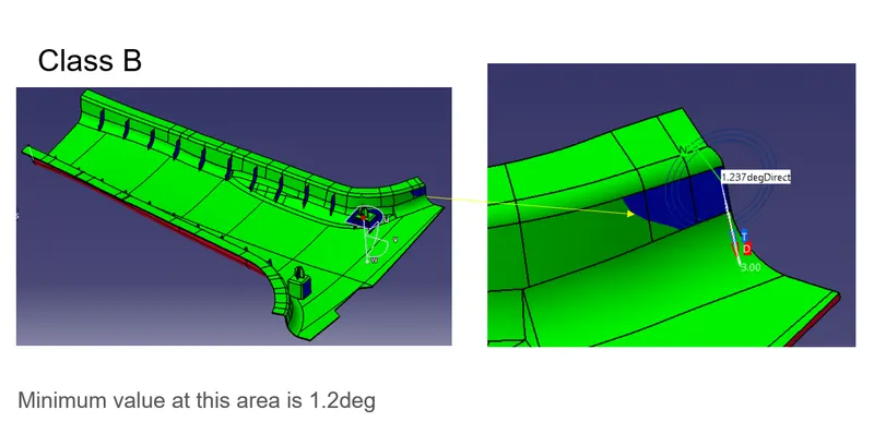
Class B surface
- Invisible Surfaces.
- Surface mostly don't have textures
- The surface needs to be created according to the class-A surface.
- Having all features(Rib, boss, snap, etc) in B-side surface only.
- Surfaces which is having TANGENT CONTINUITY IS CALLED class-B
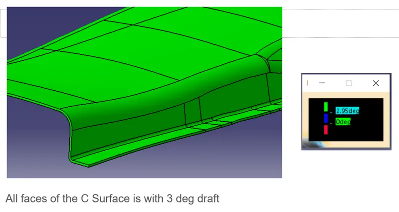
Class C Surface
- Class C finish allows more imperfections than Class A or B.
- It is often specified for interior surfaces not readily visible, surfaces that will be covered by another part when assembled, or surfaces that the Customer feels do not need to meet a high cosmetic finish.
- It is used for parts or surfaces which are not viewed after installation or viewed only for service.
- The distance between each point of the edges of two neighboring patches is no more than 0.05 mm.
- The angle between the tangents to the surface on the edges of two neighboring patches is no more than 30’ (0.5◦).
- Shape tolerance is not applied.
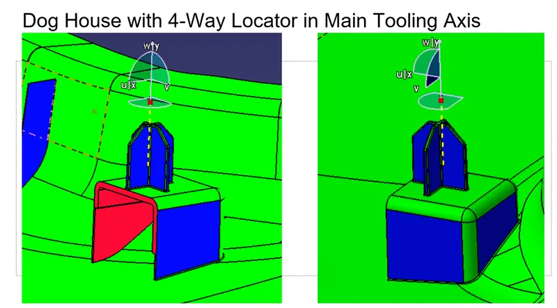
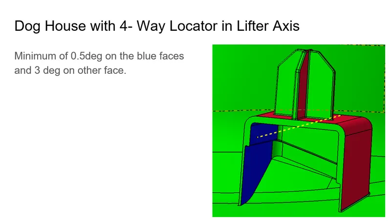
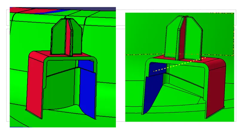
Dog House
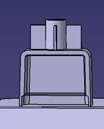
A dog house is a 4 sided box attached to a flat surface which usually requires a riser/slide to mold. In other words, it has 3 sides and a “roof”, where the roof usually has a hole for attachment purposes.
4-way Locator
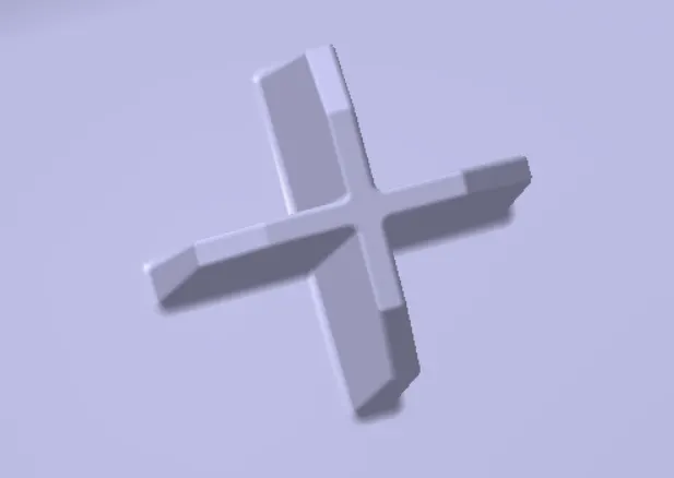
4-way means you prevent movement at 2 axis (+X, -X, +Y, and -Y) on the plane. Generally, you have a cylindrical pin on the fixture and a circular hole at the workpiece part.
Rib
Design Rules for Rib Creation
1) Rib thickness
Ribs should be designed to be 40 percent of the nominal wall thickness. Thinner does not provide much structure and may be hard to fill. Thicker ribs are tempting, but they can begin to introduce sinks on the cosmetic surface.
If a rib is too thick, the point where it attaches to the primary wall or boss will be thickened as well. This can easily cause sink marks, warp, and voids where there is this excess material. In particular, sinks are visible indicators of bad design, which will affect the appearance of your finished part. If severe enough, sinks and voids can reduce a part’s strength as they become concentrated centers of stress. To prevent these problems, it is recommended that your rib’s width fall between 0.5 and 0.75 times the primary wall’s thickness.
When selecting a rib width, it is important to keep in mind that the shrink rate is not the same for all materials. High shrink plastics should be made thinner, while low shrink plastics can be made thicker. Low shrink materials are less likely to cause sink or warp because they do not exert as much pull on the surface or adjacent thin walls as high shrink materials do.
2) Rib height
For maximum effectiveness, rib height should be no more than 5 times the nominal wall thickness. Since the rib will be thinner than the wall, it may be hard to fill it if it is taller.
This height cap is recommended because if your ribs are too tall, they can break during use or ejection from the mold.
3) Rib draft
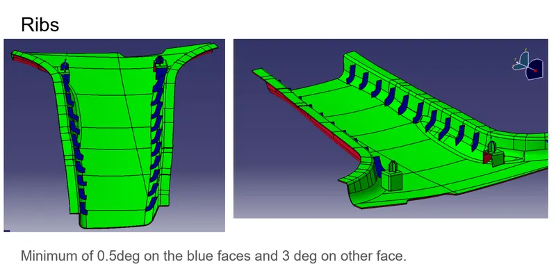
A minimum 0.5-degree per side minimum draft will ensure that they release from the tool during molding. The draft is especially important for ribs so that they can be removed without damage or breakage.
4)Rib spacing
Increase the number of ribs rather than their height in order to increase stiffness. Ribs should be spaced a minimum of 3:1 ratio with a height of ribs apart from one another.
Height/width Ratio
3:1 Steel
2:1 Preferred
Prevent thin steel conditions to prevent it from cracking.
If ribs are closer than that, you run the risk of the ribs not being able to cool quickly. This means the part will have to stay in the mold longer before it can be ejected, which will increase your cycle time and your part cost. Another reason spacing is important is that ribs that are too close together will make it so there are thin sections of your mold. These are prime areas for damage to the mold to occur.
5) Rib Fillet Radius
The base of a rib should always be rounded with a radius to prevent an area of concentrated stress in the part. Sharp corners also hamper the plastic’s flow rate down into the rib, meaning it may not be able to fill all the way before the material starts to cool, which will cause voids. 0.25mm is the maximum fillet radius for the ribs.
6) Rib Root Thickness
Ribs create thick sections at the root (defined by the circle below). This area is thicker than the nominal wall thickness and susceptible to sink.
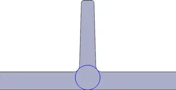
7) The minimum thickness at the tip of the rib must be 0.75mm.
8) Ribs on the opposite sides of walls must be offset.
9) Ribs should be connected to other structural features where possible.
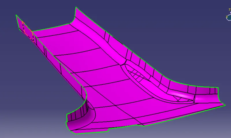
Determining the Tooling Axis
1) Connectivity Of Surface
After receiving the class A surface model the connectivity of surfaces was checked. It helps to find discontinuity within the surfaces of the model. The Connectivity of the surface can be checked in three different ways
Join Operation
Boundary Operation
Disassemble Operation
After verifying the connectivity of surfaces these operations were deleted.
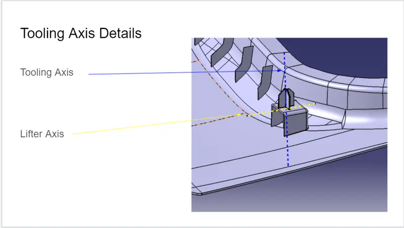
2) Determining the Tooling Axis
The Tooling axis is the axis along which the mold or core and cavity opens. The tooling axis for a model has to be decided so that no additional works are needed on it which helps to reduce the cost.
Tooling Axis is created by bisecting the lines in the master section with a center point between them as reference.
Creating Class B Surface
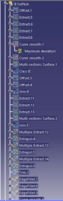
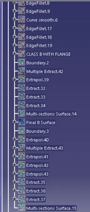
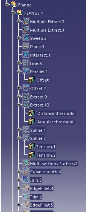
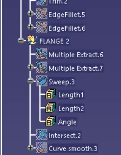
Class B surface is created by offsetting surfaces to the thickness ie 2mm. Class B is created along with Flanges.
Class C
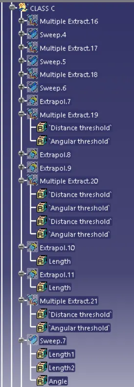
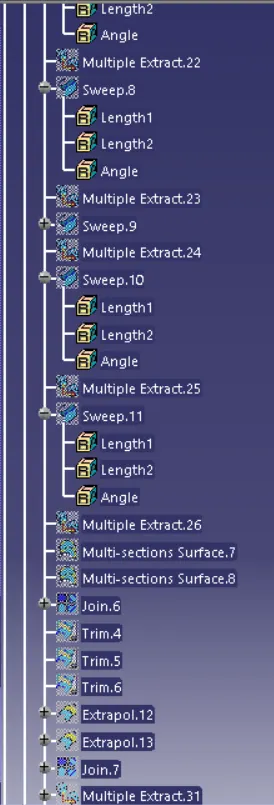
Class C is created by extrapolating the edges from the class A Surface. Edges are properly swept along the tooling axis, trimmed to get the final C surface.
The Class B and Class C surfaces are trimmed to get the final closed surface. It is made a Closed body using the closed body feature.