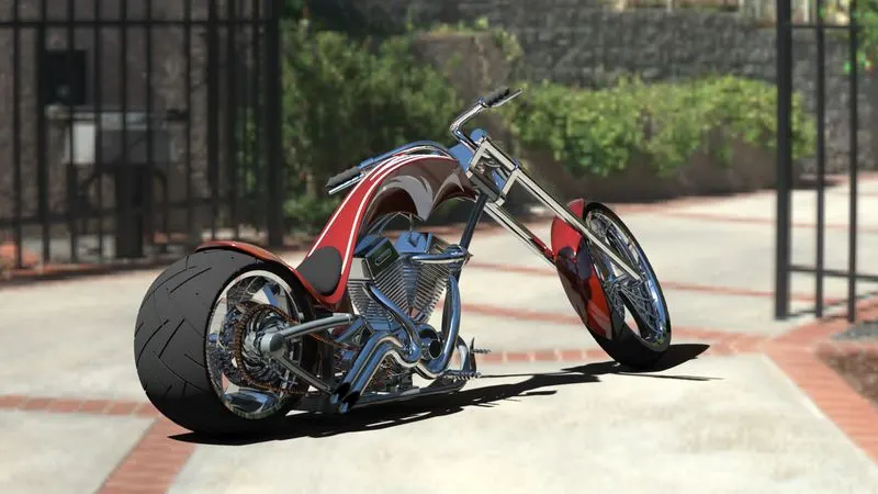
Modelling Of American Chopper
MODELING OF AMERICAN CHOPPER ON SOLIDWORKS
By:
LIJITH V M
Introduction
In this project, we are to learn the entire modeling of an American chopper using Solidworks for modeling and Solidworks Visualize for rendering.
The different components of the American Chopper we deal with are:
- Chassis
- Engine with exhaust system
- Front wheel and Rear wheel with rims sprockets and calipers
- Front fork along with handlebars and grips
- Front and Rear Fenders
- Oil Tank
- Chain and transmission belt
- Kickstand and foot pedals
- Gas Tank
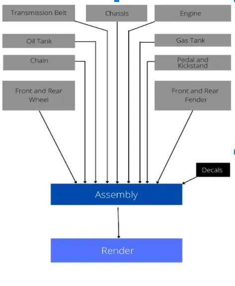
Every part of the chopper is made separately with proper sketching and modeling. After designing the part components, we have worked upon the assembly and the photo rendering of the chopper which gives it a complete and realistic view.
1. Flow Chart
2.Tools / Features Used
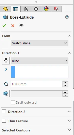
- Extrude Boss: Extrude Base is the feature that helps us to convert 2d drawings into 3d by adding thickness in the 3rd dimension. After completing the sketch select Extruded Boss/Base on the Features toolbar. The Boss-Extrude feature button will prompt you to set parameters as shown in the figure where we have options to set depth, direction, and plane from which extrusion has to take place, etc.
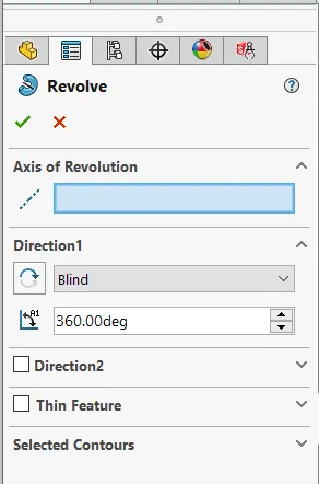
2. Revolved Boss Feature: It is used to create a solid 3D model around an axis. You can revolve the sketch around an axis to add materials to it. After completing the sketch, keeping the sketch selected we revolve the sketch about a particular axis or reference axis.
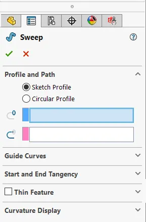
3. Sweep Boss / Sweep Cut: It is used to add or remove material from a solid model or part by sweeping a completely closed profile along a path. Swept Boss or Base-up solid material to the body of design and Swept Cut removes material from the body of the design.
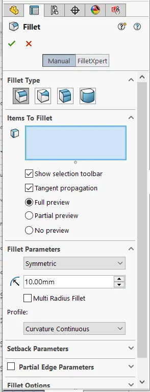
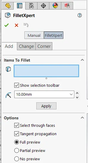
4. Fillet: Fillets are used to round off edges and/or corners. Fillet adds or removes material, depending on whether the edge is internal or external in order to convert edges or corners to rounded ones. There are manual fillet and fillet expert options that will be useful depending upon the complexity of the model, or no of models we have to add fillet.
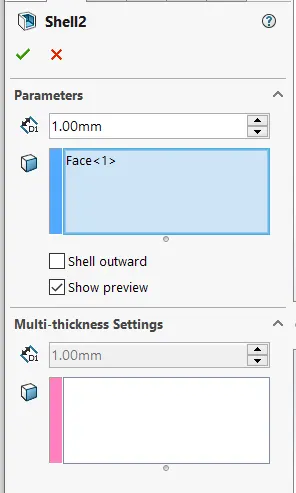
5. Shell: The shell tool hollows out a part, leaves open the faces you select, and creates thin-walled features on the remaining faces.
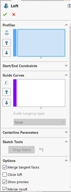
6. Loft Boss/ Loft Cut: You create a loft using two or more profiles. Only the first, last, or first and last profiles can be points. All sketch entities, including guide curves and profiles,
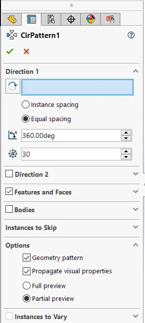
7. Linear Pattern/Circular Pattern/Curve driven Pattern: It is used to create multiple instances of one or more features that you can space uniformly along one or two linear or circular paths. In a linear pattern we have to select the linear path pattern that needs to be followed, In a circular pattern, we have to select the circular path the pattern needs to be followed. In a curve-driven pattern, we have selected the curve along which pattern has to be followed.
8. Mirror: It allows us to duplicate features just like the mirror image. We can mirror the features along a plane, axis, face, reference geometries, etc. We also have the option to mirror patterns, bodies, multi bodies which make the designing a lot easier.
9. Projected Curve: It is a very useful tool to create complex 3D curves. Drawing curves in different planes with some common points and combining them helps to get smooth 3D curves with this tool.
10. Split: Split works just like the extruded cut tool, but the split has a lot more options to cut out parts. It helps to cut out intersection parts, remove unwanted interior or exterior parts.
11. Reference Geometry: Reference geometry defines the shape or form of a surface or a solid. Reference geometry includes items such as planes, axes, coordinate systems, and points.
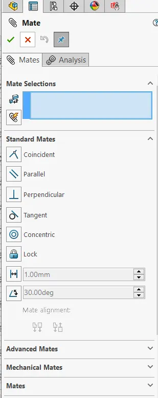
12. Mate: Mates create geometric relationships between different parts we made. It helps to create different mates with relation of concentric, parallel, perpendicular, tangent, etc.
3. Parts of American Chopper
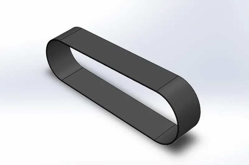
1. Transmission Belt: Extruding the sketch helps to create a transmission belt. The outer edge is filleted and the appearance used is a matte rubber.
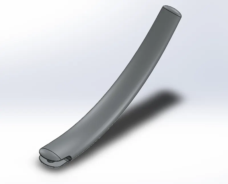
2. Kickstand: The kickstand is designed with the help of loft and dome features. The reference plane helps to create two different profiles to create the desired shape for the kickstand. Edges are properly filleted and a proper joint to mate kickstand and frame so that moving it in the desired angle is possible. Chrome appearance is given to kickstand.
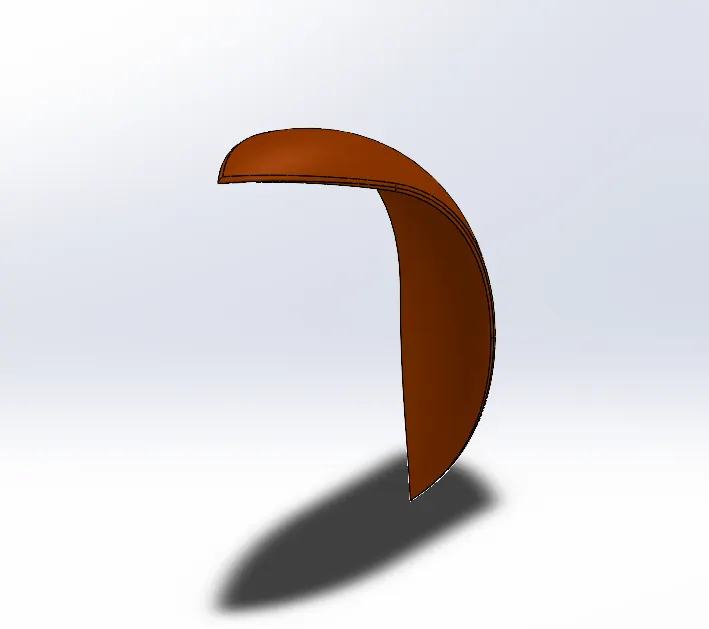
3. Front Fender: A proper sketch is revolved to get the desired shape of the front fender. Split Tool was used to making the edges look more like fenders. Siena's appearance was given to it.
4. Rear Fender: The same method has been applied in the rear fender as it was in the front fender the only difference between the two is the sizes of both the fenders which vary accordingly with the size of the tire. Both the parts are metal and painted sienna which gives a bright orange texture.
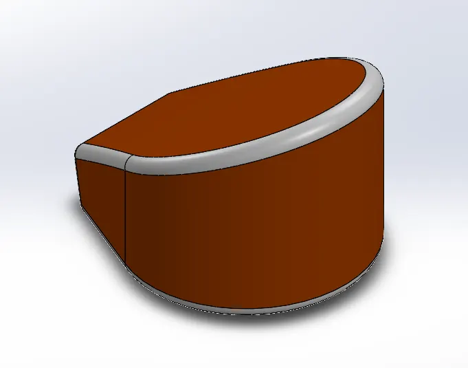
5. Oil Tank: The bottom sketch of the oil tank was made and extruded. The Combine feature was used with another extruded sketch part to get the desired shape of the tank. shell function is used to make the oil tank hollow of particular wall thickness. Edges were properly filleted. The metal body is painted with the sienna color and the filleted edges are given white paint.
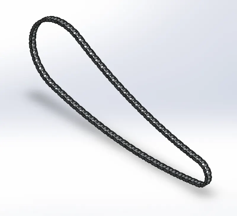
6. Chain Link: Two chain links are made separately and made into blocks so that we can use them anytime we wanted in the model. These chain links were arranged around the sketch which will help give it a shape that connects the front and rear sprocket of the American chopper. A curve-driven pattern, linear pattern, and circular pattern was used to arrange the chain links in the sketch. We mirrored the face of the links to the pins in the block diagram with respect to the mid-plane. A finely finished chrome-plated metal is used as the appearance of the linked part.
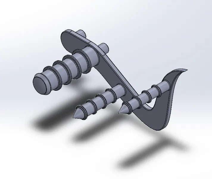
7. Pedal: Proper sketch was made and extruded so that we get desired shape for the pedal to attach footrest pins. Pins were extruded at proper locations in the pedal plate and to make proper joints with the frame. Circular patterns were made in pins with the help of patterns. Chamfers and fillets are applied at different edges.
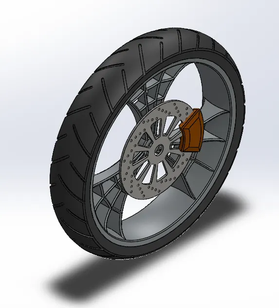
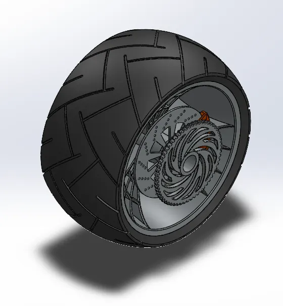
8. Front and Rear Wheel: Front And rear-wheel consisted of the rim, rotor, caliper, tire, and sprocket. Revolve of the sketch was used to get the rim shape of a wheel. Spokes were sketched with the help of a dynamic mirror and pattern. A spider web design on the spokes a sketch is made on the face of the spoke with the help of splines. The disk plate was made with a proper pattern of holes in it. The calipers are sketched now on the face of the disk and extruded on both sides which are then chamfered to attain the desired look and the edges are filleted, now the sprocket is designed with proper teeth on it. With the help of three-point rectangles and revolved they as patterns. And made the pattern extruded cut on the surface of the tire to get grips on it. Solid parts were given appearance in the end. Chrome finished Rims, Sienna metal painted Caliper, Chrome finished sprocket, and matte rubber tires.
9. Front Forks: - Front fork consists of the front fork, handlebar, headlights, brake and clutch levers, wires, and handle grips. Half of the fork is made and mirrored to get the final front fork. A rod was made with the help of a revolving tool. An extruded part is curved along the top of the handle facing down which is the headlight. To make it hollow a part is extruded cut internally from the face of the headlight. The edges of the part are filleted to give it a headlight curved lens look in the front. With the help of a projected curve and sweep, we made a handle for the fork. And used 3-point curves to create grip on the handle. The brake handles were made and a projected curve was made to sweep the wires for the brake and clutch. Created a plane to mirror the fork and all the parts are combined together to form the final 3D model.
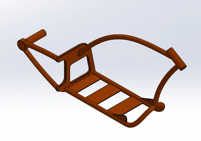
10. Chassis: 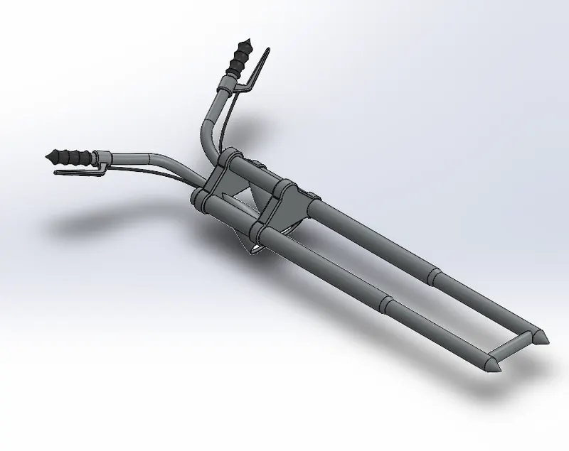 Chassis is the important part where many parts of the chopper got attached to. Projected curves are used to create the bears of the chassis. Plated base was created to place the engine in the chassis. Sweeps are created to create rods to place the fuel tank and revolved joint for the front fork to get attached to the chassis. and To join the chassis with the front fork a revolve part is created at the front and other the extra parts between the two swept rods are extruded, now to make the attachments with the pedals and the kickstand two geometries are created extruded, and the undesired part is extruded out. In the end, all the sharp edges undergo the desired fillet. A new plane is added for the purpose of further assembly purposes.
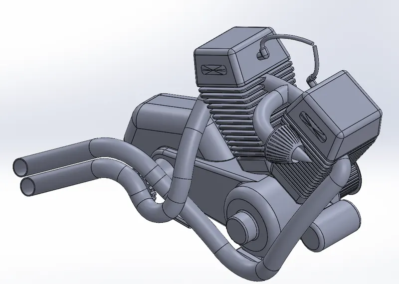
11. Engine, Motors, and the Exhaust System: Sketching and extruding it was the steps to get proper shape for the engine. For the Transmission belts and chains, Sprockets of suitable size were made on both sides of the engine. The teeth of the sprockets were made easier with the help of a circular pattern tool. Draft angle feature was used along with boss extrude to get the shape of the Engine cylinder. The mirror feature helps to create the other cylinder easily on the engine. Fillets and chamfers were added at appropriate locations. Utilized Spline and Sweep feature to make air filters and spark plugs connecting to the gas tank. Now comes the designing of the exhaust pipe from the engine, to do that two projected curves are made both the curves are then joined together to form a composite curve. Circular profiles were made at the end of the curve to apply the sweep feature and so as to get smooth cylindrical pipe like a sweep. The same process is carried out for the second pipe and at last, the wires are attached to the spark plug with two different sweeps. The total appearance given to the engine is chrome-plated metal.
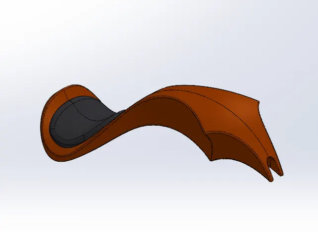
12. Gas Tank: Gas Tank was made with the help of surface features. Additional reference planes were made and two sketches are drawn on them which are surface swept. Surface trim was used to attain the design of the tank. A plane is added and a surface loft is created to make a curved front face of the tank. The boundary sweep feature helps to create surface joining the front face by selecting boundary edges. Mirrored the entire part and knitted them together to get the entire gas tank structure. Extruded surface on the tank and filleted the edges to take a seat. Used surface loft and knitting tools to cover the bottom of the gas tank. Made a sketch on the face of the gas tank to cut sweep the bottom surface of the tank to make proper attachment to chassis during assembly. A shell is created at the end to make it hollow. A sienna appearance was given to the part and grey cotton material is used for the seat.
4. Assembly
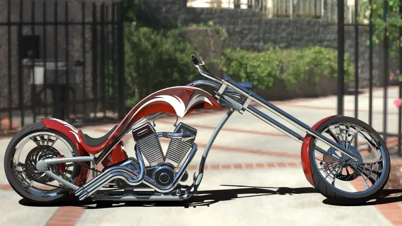
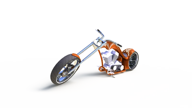
To make an American chopper we have to assemble all the parts we made separately. The assembly was made to chassis so that floating the entire model was possible. We begin by bringing in the chassis first and bringing the engine into it. The engine was mated perfectly, applying coincident relations. after we bring in the pedal to mate with chassis applying coincident and concentric mate. The same pedal is then mirrored on the other side of the chassis with defining the properties of the opposite side. Then we brought in the kickstand and matted it using the concentric and coincident relation. An angular mate is provided with the body so that the kickstand works as it is with the model. Then the transmission belt mated to the engine drivers. The oil tank is directly placed and matted above the engine. The concentric mate was used to mate the rear wheel with the chassis and also parallel mate to make it properly oriented in the chassis. the rear fender placed above the rear wheel. The chain was placed on the sprockets using the width mate. The gas tank is matted with a distance mate and a parallel mate with respect to the chassis and then the front fork is mated coincidently with the upper part of the chassis and a width mate. Angle mate with certain limits is applied with the fork and the chassis. Finally, the front wheel is attached with the front fork as it was attached in the case of the rear wheel and the fender is placed above the front wheel as shown in the diagram.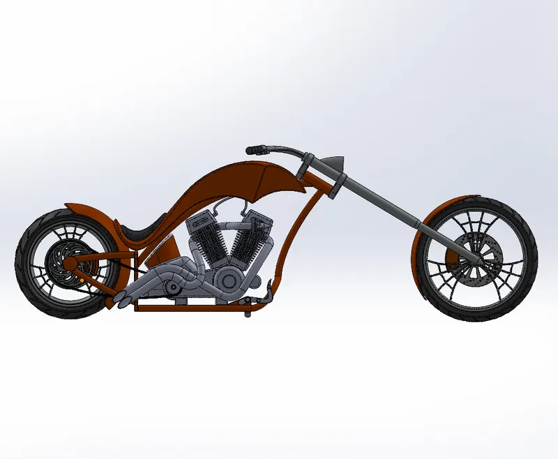
5. Rendering
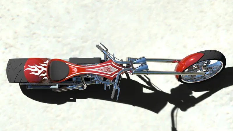
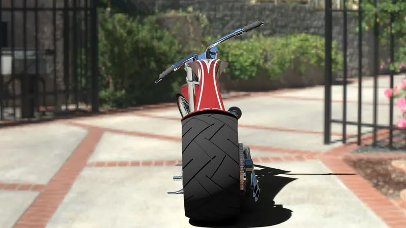
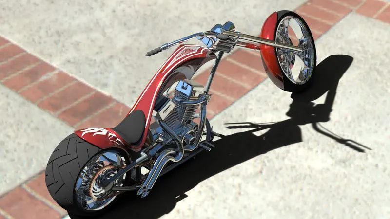
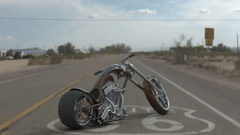
The rendering is possible with render tools and using Solidworks Visualizer. Photoview 360 was enabled to render the assembly. Decals are added to the parts to make the chopper look more stylish. There are more options available like integrated preview and preview window which will help to get a better preview before the final render. The camera was set the desired lights and the focal distance creating the angle of the view and saving the camera angle which gave a realistic view to the chopper. Final Render will give it a more realistic view.
The Solidwork visualizer is a much more realistic tool for rendering. We have to import the assembly file to the visualizer. Wide options to add environment appearances, color, camera, brightness, shadows, etc. Adjusting the view, perspective, changing the appearances of the model and different environments for making different renders. High-quality renders take time to get completed in Solidwork visualize and it gives high quality rendered images of American chopper in different environments at the end.