Week 9 - Project - Master Section Development
Title- Week 9 - Project - Master Section Development
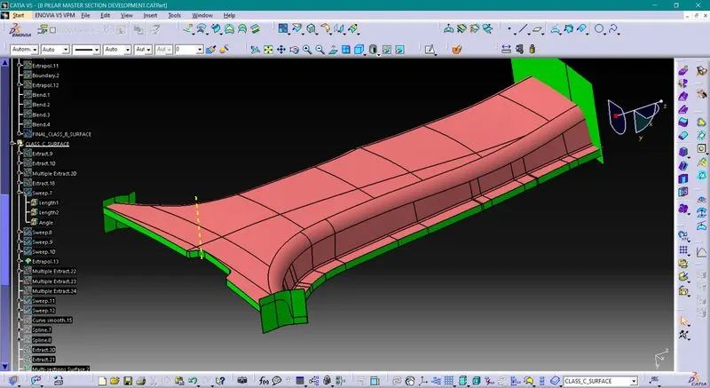
Aim- To create B-Pillar part using given class A surface along with all necessary B side engineering features
Objectives-
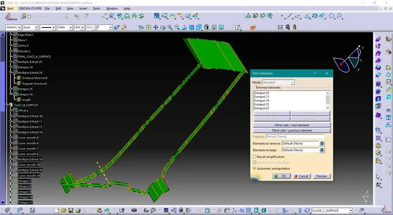
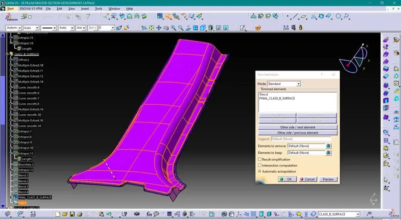
1. To create class B & C surface using class A surface
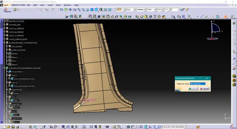
2. To create solid part using close surface body
3. To create all necessary engineering B side features with proper draft
Creation of Tooling Direction-
Tooling Direction: -
Tooling direction is main consideration for plastic part and mold parts because it defines movement of mold part and possibility of plastic part to come-out from mold part (Core and Cavity).
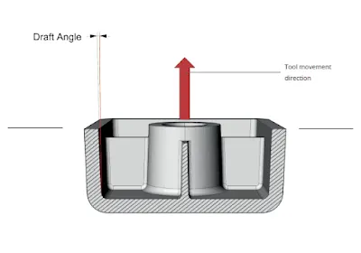
- In Molding machine arrangement is given to open the mold along a direction which is known as Tooling Direction.
- In other words. The mold is built from two separate halves (Core and Cavity) and tooling direction basically define the direction of mold pulls apart.
- Tooling direction is known as primary direction.
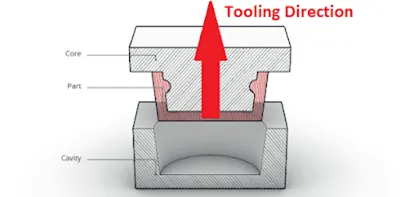
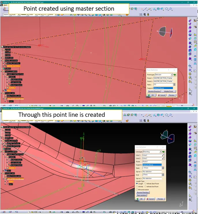
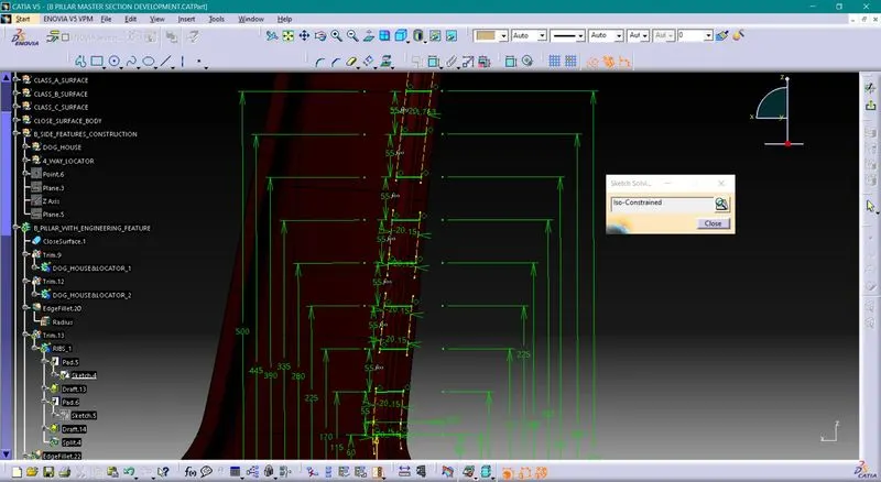
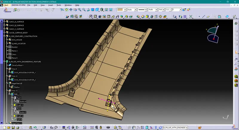
In plastic part manufacturing, part will be created by sending high pressure melted plastic into recess available between core half & cavity half & holding it for seconds to solidify. After solidifying part will be ejected from mold.
When developing parts for plastic injection molding, applying draft (or a taper) to the faces of the part is critical to improving the moldability of your part. Without it, parts run the risk of poor cosmetic finishes, and may bend, break, or warp due to molding stresses caused by the plastic cooling. Equally important, an absence of draft may prevent parts from ejecting from the mold, damaging not only the parts, but possibly the mold itself—a costly and time-consuming detour.
Draft analysis is used to evaluate or double check one's work. When making a part that will be molded, the analysis will verify that all surfaces are favorable for being pulled from a cavity. It may also highlight or give insight to "trouble" areas.
Simple parts may not need this. More complex parts that need multiple cores or slides, it becomes very helpful.
1. Draft analysis for class A surface-
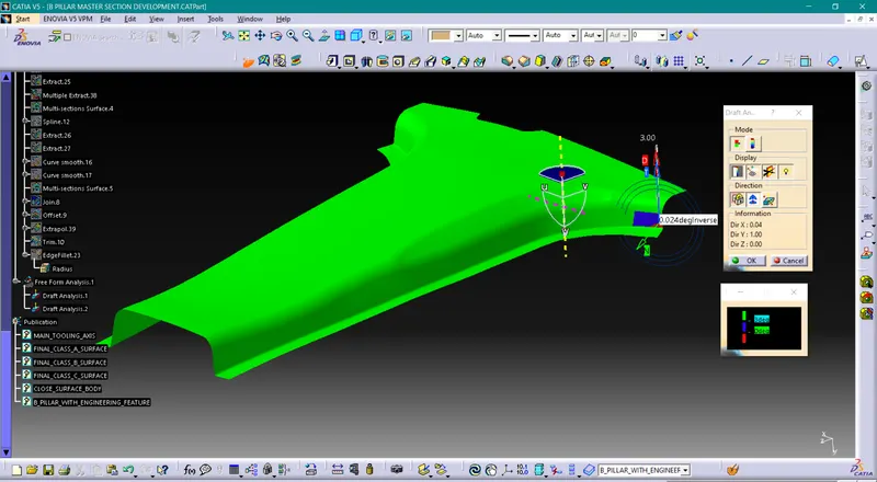
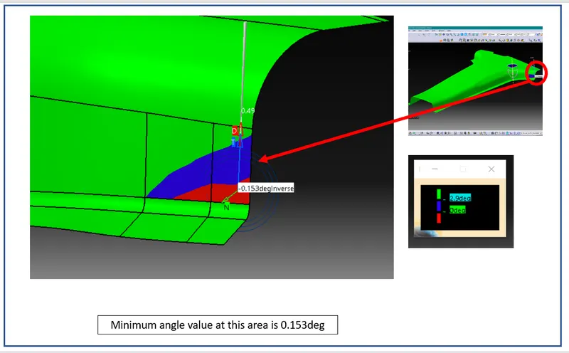
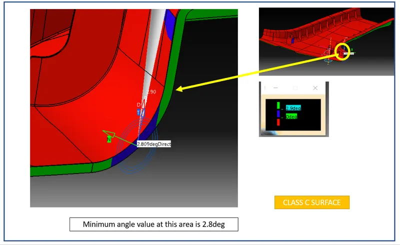
As complete part is confirming that it will clear the draft except small patch in the corner.
In such situations, first need to check the tooling direction. Try to modify tooling axis so that all surface will confirms positive draft.
Otherwise, this information sent to the styling team & ask them to modify & improve this patch.
In some cases, this can be ignored as it is very small error.
2. Draft analysis for the solid part-
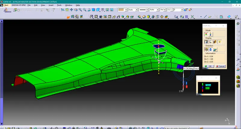
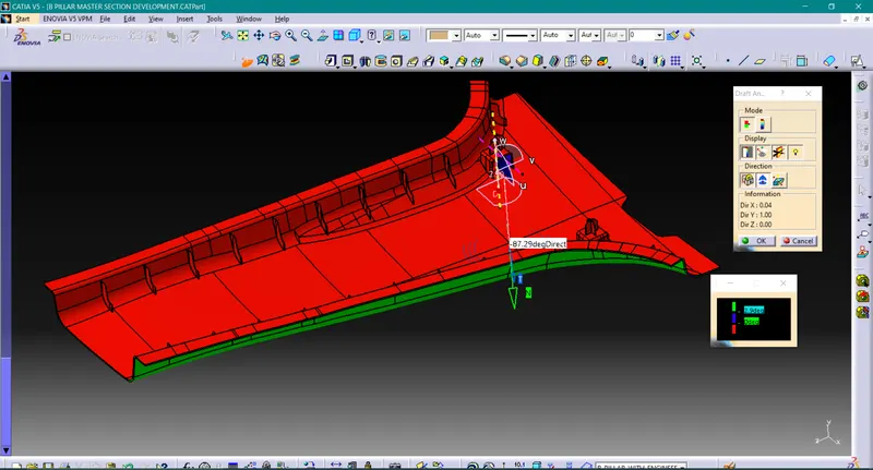
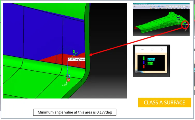
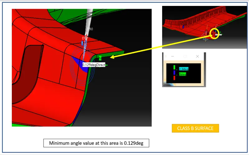
By neglecting error, observed in class A surface, solid part has created as explained in earlier sections.
The above images show A, B & C surfaces with draft analysis by considering 3deg draft angle.
This part is confirming draft analysis.
3. Draft analysis for Dog house outer surface-
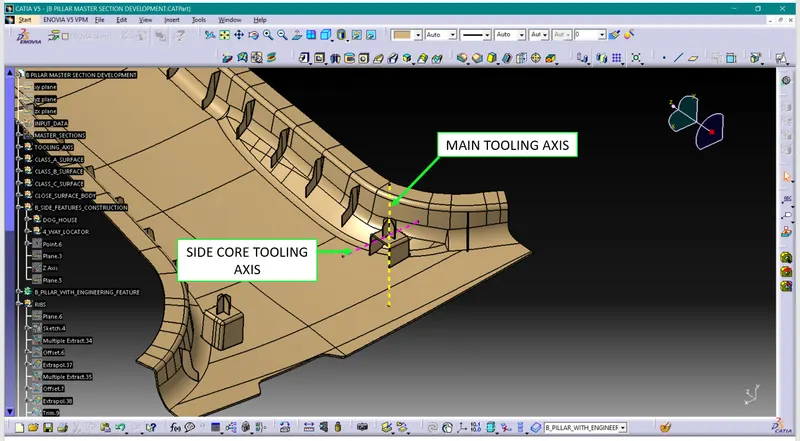
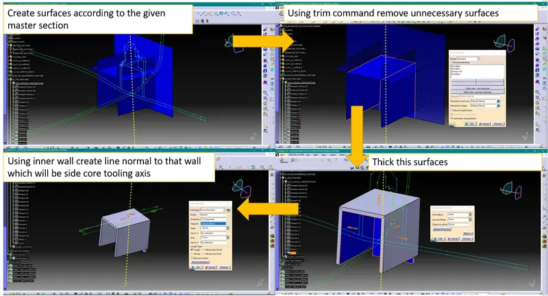
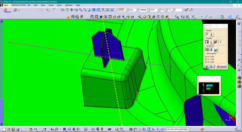
For dog house there will be two axes are available main tooling axis & side core tooling axis.
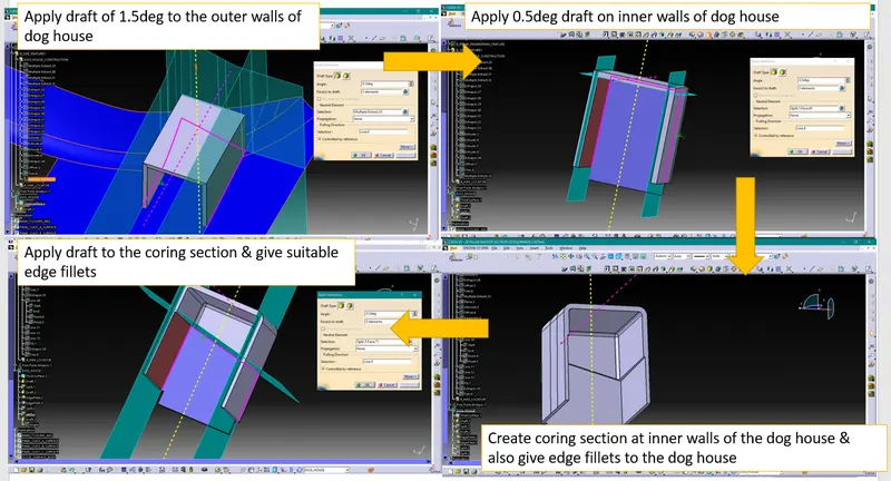
Outer surface will be checked using main tooling axis with 1.5deg draft angle.
4. Draft analysis for Dog house inner surface-
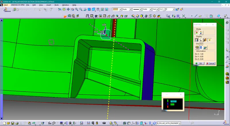
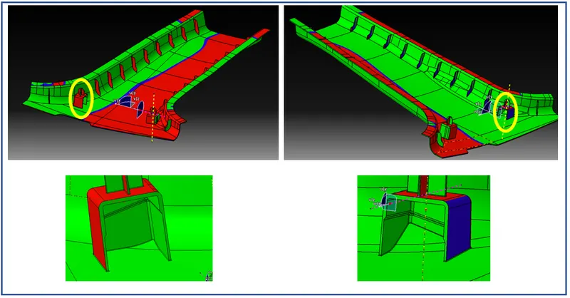
While performing draft analysis for inner surface side core tooling axis can be used with 0.5deg draft angle.
5. Draft analysis for the 4-way locator-
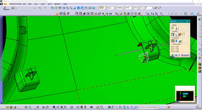
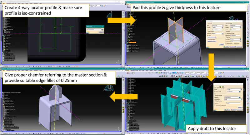
For 4-way locator 0.5deg draft is considered.
6. Draft analysis for the ribs-
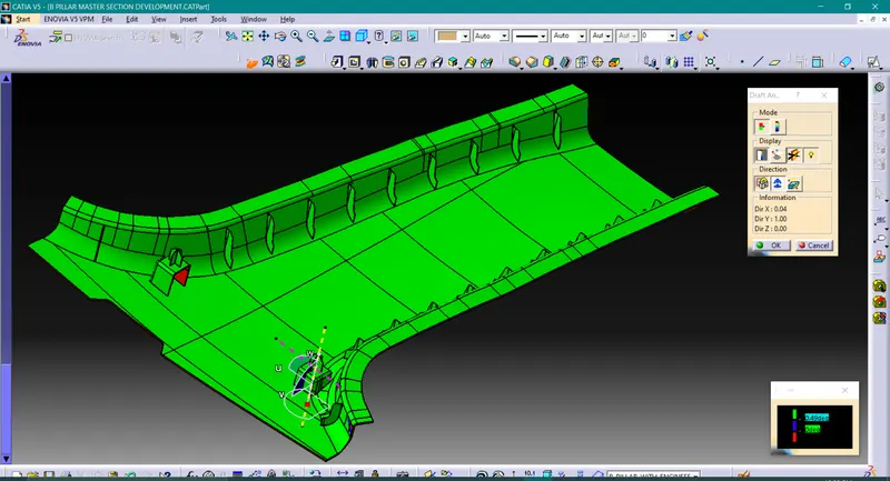
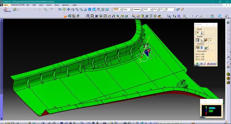
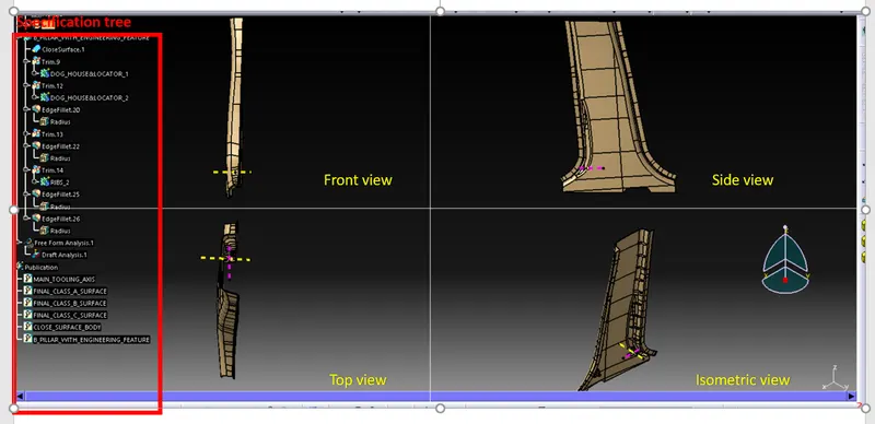
Different orientations of part & detailed tree structure of part-
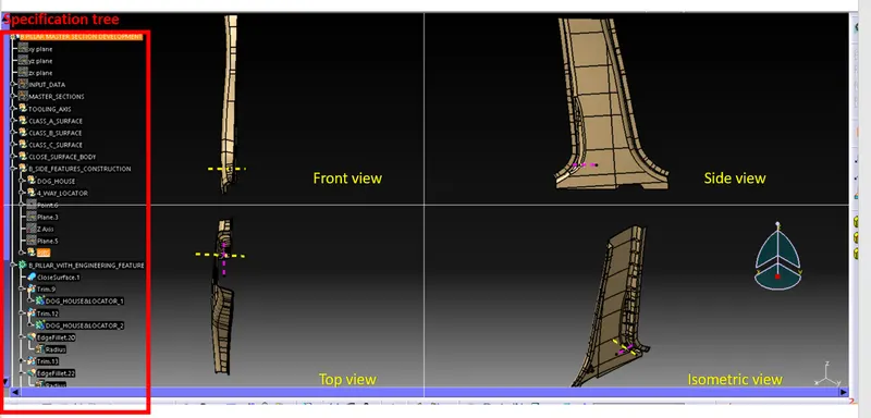
Conclusion-
1. We have created class B & C surface using class A surface
2. We have created solid part using close surface body
3. We have created all necessary engineering B side features with proper draft