Design of HOOD ASSEMBLY considering Euro-NCAP rules and using NX cad.
DESIGN OF HOOD ASSEMBLY
Aim- Design Hood outer panel, inner panel and the necessary reinforcements.
1.0 Introduction to Hood or Bonnet-
The hood or bonnet is the hinged cover over the engine of motor vehicles. Hoods can open to allow access to the engine compartment, or trunk (boot in Commonwealth English) on rear-engine and some mid-engine vehicles for maintenance and repair. Hood is mainly the assembly of hood outer panel which is a styling surface
On front-engine cars, the hood may be hinged at either the front or the rear edge, or in earlier models (e.g. the Ford Model T) it may be split into two sections, one each side, each hinged along the centre line. A further variant combines the bonnet and wheel arches into one section and allows the entire front bodywork to tilt forwards around a pivot near the front of the vehicle (e.g. that of the Triumph Herald).
Hoods are typically made out of the same material as the rest of the body work. This may include steel, aluminium, fiberglass or carbon fibre. However, some aftermarket companies produce replacements for steel hoods in fiberglass or carbon fibre to make the vehicle lighter.
A hood may contain a hood ornament, hood scoop, power bulge, and/or wiper jets

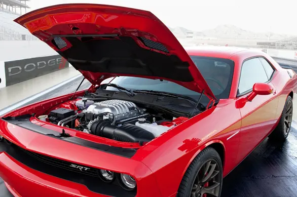
1. Front flip opening hood 2. Rear flip opening hood
2.0 Design considerations of Hood-
While designing the hood of a car general considerations which must be taken into account are explained as follows
2.1 Hood head zone for striker locking-
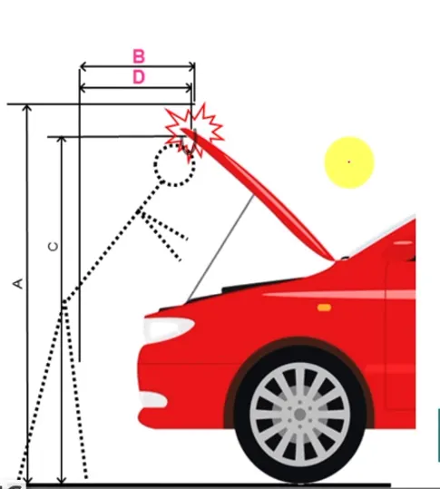
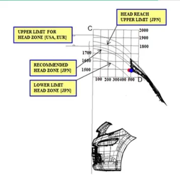
Hood will provide access to the engine compartment after opening the hood. To perform any kind of operation hood must be at such height so the hood will not hit to the head of the person who is doing operation. For this reason hood height in opening condition will be always above the average height of humans in that region so that no human will get hurt.
Following data will be helpful to decide the hood opening height.
2.2 Hood Stay-
A hoodstay is an apparatus for an engine room of a car, which can safely keep an engine hood in an open state even if an external force abruptly generated due to vibration, wind and can facilitate an opening/closing operation of an engine hood.
Hoodstay always designed in such a way so it can support coplete weight of the hood and it must be get accomodated easily under hood when in open condition.
There are two types of hoodstay
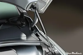
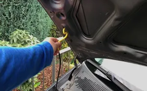
1. Gas stay 2. Support rod
2.3 Pedstrian safety-
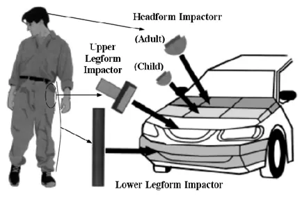
While designing the hood it will be more important to consider the safety of then pedastrian. For this we need to obtain region over the hood on which pedstrian will going to hit with respect to the different body parts. Also to study we must consider the adult and child height as well. All these rgions are studied in the crast test of every car and results are obtained to make sure the pedstrian safety
. 
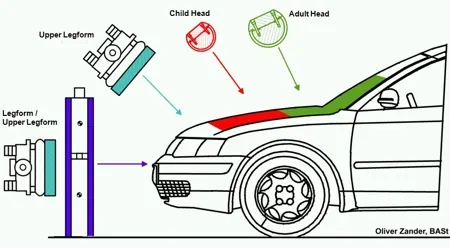
2.4 Mastic data-
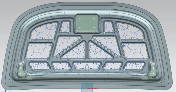
The assembly of hood contains hood outer panel which encloses the hood inner panel. Hood inner panel is acting like reinforcement of the outer panel. As both inner and outer panels are of metal, when directly are in contact will produces noise and vibrations. These noises and vibration will make uncomforting to the passengers inside the car. To reduce these noise and vibrations mastic sealant is applied in between the inner and outer panel.
Mastic sealant is paste like substance which is applied and get hardened after heating.
Following are point of application of mastic sealant and area which is covered by mastic sealant is shown
2.5 Force Distribution towards hinges-
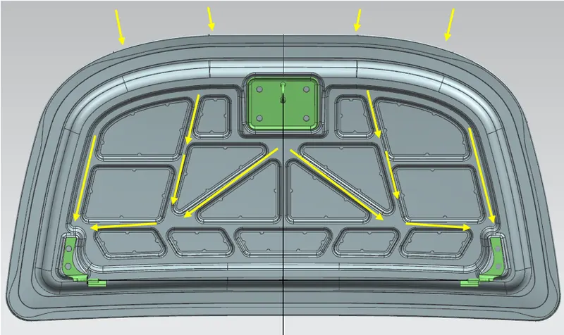
When designing hood, designer should consider the force distribution when vehicle will get hit to an object from front side of the car. Designer always trying to make such design in which all forces will travel along the flanges towards the hinges. Doing this will results in proper distribution of force and it will also reduce shock impact to the passengers inside the car.
3.0 Hood panel assembly components-
Following are the components which will form the hood assembly
3.1 Hood Outer Panel-
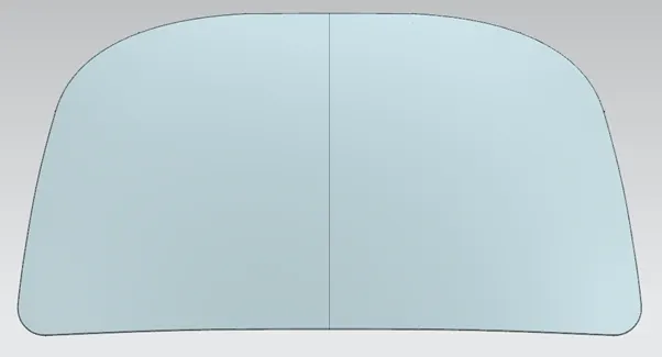
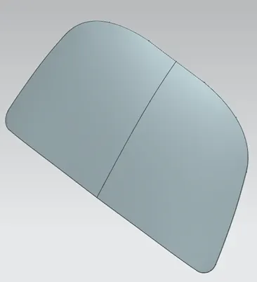
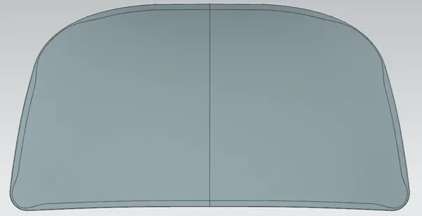
It is the styling surface. This surface is the one which is visible when the hood is in closed condition. Mostly this outer surface is painted so to improve the appearance of the car. The outer panel encloses the inner panel.
3.2 Hood Inner Panel-
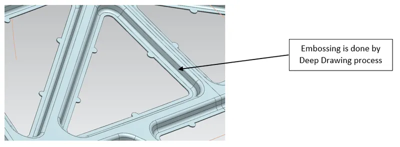
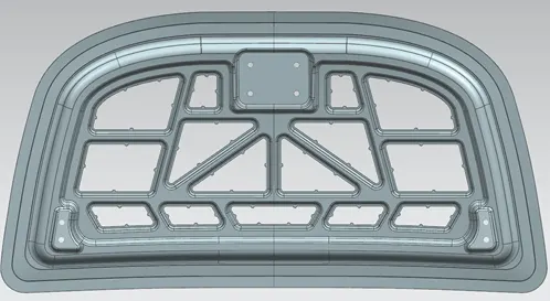
Hood inner panel is the one which under the hood outer panel. Inner panel is acting like reinforcement of the hood outer panel providing strength to the outer panel and safety to the car in case of accidents. Deep drawing, punching, etc are some of the processes by which inner panel is made. To reduce the weight of the inner panel wherever it is possible cut out is made.
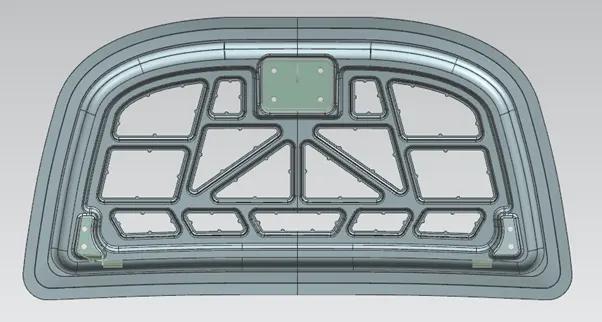
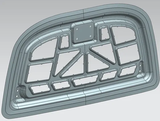
Hood panel is visible when hood is opened.
3.3 Latch Striker-
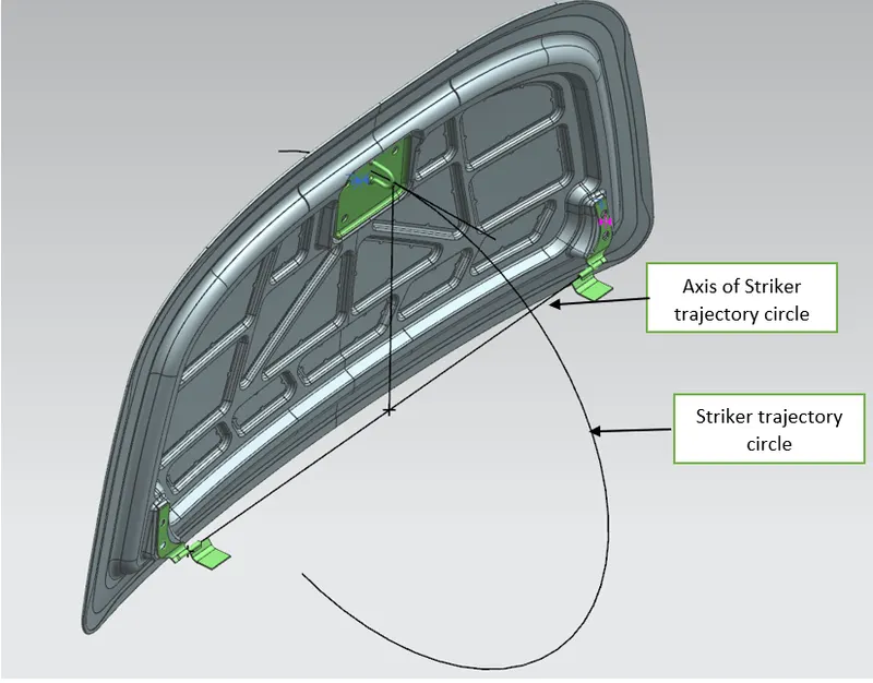
Latch striker is device which will used to lock the hood with the engine compartment. It will hold the hood assembly firmly so hood will not open until lock is lever is pulled. Striker will get locked into the latch lock which is available engine compartment.
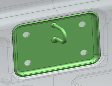
3.4 Hinge Assembly-
Hinge assembly will allow hood assembly to move in circular path while opening and closing of the hood. Hinge assembly contains hinge inner panel side and hinge engine compartment side which are fixed on inner panel and engine compartment respectively on both left and right side.
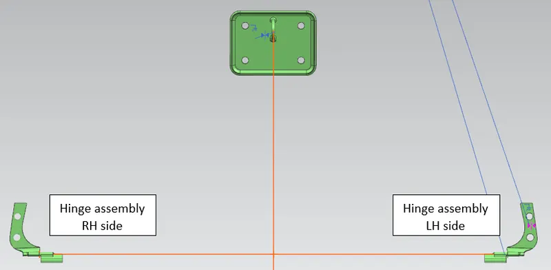
4.0 Input Data for Design of Hood-
Following data is provided with us to design the Hood Inner and Hood Outer panels.
4.1 Hood Thickness Information
- Outer Panel Thickness = 0.75mm
- Inner Panel Thickness = 0.75mm
- Reinforcement Thickness = 1.5mm
While designing the hood we need to maintain the thickness as mentioned above.
4.2 Master section
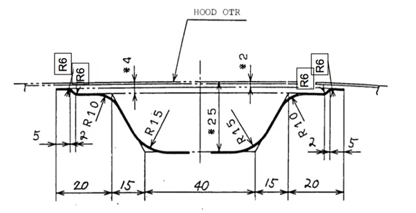
This master section is used to develop the inner panel.
5.0 Manufacturing processes for Hood Inner panel and Outer panel-
Hood inner panel can be manufactured by performing operations on the thin sheet. Some of them are as follows
5.1 Deep Drawing-
The deep drawing process is a forming process which occurs under a combination of tensile and compressive conditions. A flat sheet metal blank is formed into a hollow body open on one side or a hollow body is formed into a hollow body with a smaller cross-section. [DIN 8584]
Deep drawing processes are divided into three types:
- Deep drawing with tools
- Deep drawing with active means
- Deep drawing with active energy
In the automotive industry, deep drawing is usually carried out using rigid tools.
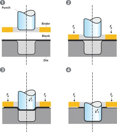
The figure illustrates the deep drawing process. The rigid tools consist of a punch, die and binder. In deep drawing, the plate holder closes after the metal sheet blank has been inserted.
Next the sheet is clamped between the die and the binder. This process slows down the flow of the sheet while it is being drawn and thereby prevents wrinkles from forming under the binder. The punch stretches the sheet over the die radius and forms it in the die. The amount of punch force necessary for forming is thereby continually increased up to the lower dead centre of the punch.
Whereas in pure deep drawing there is no reduction of sheet metal thickness, forming is achieved in stretch forming purely as a result of a decrease in sheet metal thickness. Stretch forming is extensively used for the forming of only slightly curved parts with low depth of draw (e.g. roofs, doors).
When drawing complex car body parts in practice, there is usually a combination of stretch and deep drawing involved. It is necessary that the sheet metal is stretched as well as possible without reaching the material’s limits (e.g. splits, wrinkles).
5.2 Hemming-
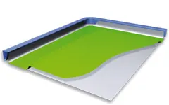
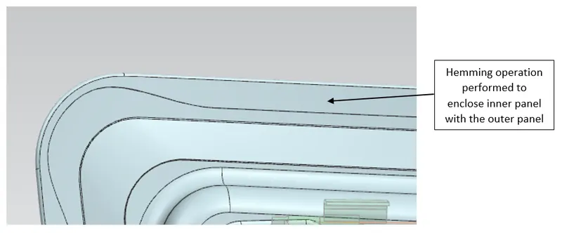
Hemming is a forming operation in which the edges of the sheet are folded or folded over another part in order to achieve a tight fit. Normally hemming operations are used to connect parts together, to improve the appearance of a part and to reinforce part edges.
In car part production, hemming is used in assembly as a secondary operation after deep drawing, trimming and flanging operations to join two sheet metal parts (outer and inner) together. Typical parts for this type of assembly are hoods, doors, trunk lids and fenders.
The accuracy of the hemming operation is very important since it affects the appearance of the surface and surface quality. Material deformations, which occur during the hemming process, can lead to dimensional variations and other defects in parts. Typical hemming defects are splits or wrinkles in the flange, material overlaps in the corner areas or material roll-in. This is why it is important to use simulation tools in order to, on the one hand, better understand the hemming process and, on the other hand, significantly reduce the number of “trial and error” loops during tryout und production.
There are various types of hemming operations:
- Conventional die hemming
- Roll hemming
In conventional die hemming, the flange is folded over the entire length with a hemming tool.
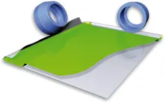
In roll hemming, the hemming roller is guided by an industrial robot to form the flange.
- Conventional die hemming
Conventional die hemming is suitable for mass production. In die hemming, the flange is folded over the entire length with a hemming tool. Normally the actual hemming is a result of a forming operation in which the flange is formed with a hemming tool after the drawing and trimming operations have been completed. The formed flange is then hemmed in several process steps. These steps include, for example, the pre-hemming and final hemming depending on the respective opening angle of the flange. Production plants for conventional die hemming are very expensive, but the cycle times are very low.
- Roll hemming
Roll hemming is carried out incrementally with a hemming roller. An industrial robot guides the hemming roller and forms the flange. Roll hemming operation can also be divided into several pre-hemming and final hemming process steps. Roll hemming is very flexible to use and tool costs are significantly lower as compared to those of conventional die hemming. However, the cycle times are much higher since the hemming is realized using a hemming roller which follows a defined path.
6.0 Software and command used-
Many 3D cad software are available now which can convert idea into 3D model. One of them NX is widely used in sheet metal part modelling. We are using the same software for designing hood inner and outer panel.
Following are some important commands we are using to make Hood assembly-
- Offset surface- Using this command we can offset required surface by distance.
- Offset curve on surface- Using this command we can offset curve on the surface irrespective of the surface profile.
- Trim Sheet- This command is useful to trim sheet with along the boundary curve.
- Law extension- With the help of this command we can extend sheet giving them length wise profile along with the angular profile.
- Emboss- Emboss is command which can be used to give deep drawing profile to the sheet.

- Face blend- This command is used to give fillet profile using faces to be fillet.

- Edge Blend- This command will be used to give fillet to the edges.
7.0 Corner Relieves to the Outer Panel-
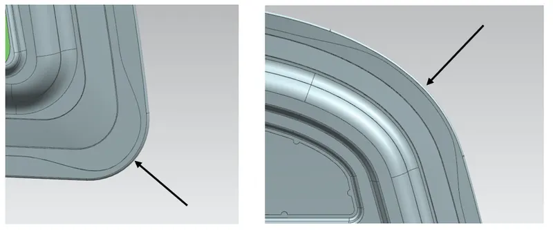
While performing hemming operation on outer panel we need to provide relieves to confirm smooth hemming at corner region. Without providing corner relieves will produces defects while hemming operations.
8.0 Draft Analysis-
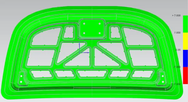
Deep Drawing is the process in which material is allowed to push forcefully into the hole with the help of punch and dies. To perform this operation there should be always positive draft so that we can remove the component easily from the die.
Draft analysis is performed to identify the regions of negative draft so that we can make correction and provide positive draft.
9.0 Final photos of Hood Assembly-
9.1 Hood inner panel-
9.2 Hood outer panel-
9.3 Hood Assembly-
Conclusion-
We have successfully designed Hood assembly by considering different parameters using NX cad. While designing hood assembly we come to know importance of safety, design considerations, manufacturing process and analysis required which was according to EuroNCAP rules.
Please find link to view my HOOD DESIGN- https://drive.google.com/file/d/1A2Cw6mi8Gtmjy9h2mzpI3OYysTVpFvRR/view?usp=sharing