Week 9 - Project - Master Section Development
Master Section Development
INTRODUCTION
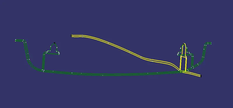
For every region we have a master section. Master section is a predefined sketch which is adoptable in different situation. With the help of these master sections we create the component.
OBJECTIVE
To create B pillar and the engineering features of the car using the given master section and given class A and then to create ribs on the B pillar.
METHODOLOGY
Skin data and master section is provided to us.
The first step is to check the continuity of the class A surface. This is to ensure that there is no gap between surfaces. If we find any then we should fix that first.
The second step is to find the tooling axis of the component.
Then we can make the component by creating the class B and class C component.
Using the master section we create a dog house and 4 way locators and then also create ribs.
After that we can do the draft analysis of the component.
DESCRIPTION
Master Section-
Master section is a predefined sketch which is adoptable in different situation.
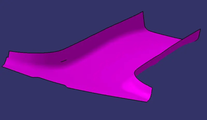
Class A surface-
Class A surfaces is a term used in most in automotive design to describe a set of freeform surfaces of high efficiency and quality.
Class B surface-
Class B surfaces are the secondary surfaces that you can see sometimes, but are less important.
Class C surface-
Class C surface are the surfaces which connects the class A and Class B surfaces.
Draft analysis-
Draft analysis is performed on components where the ejection of materials happen after the material is made inside the tools.
4 Way locators-
A 4-way pin restricts 4 degrees of freedom along 2 axes.
Ribs-
Ribs are thin, wall-like features typically designed into the geometry of a part to add internal support to walls or other features like bosses.
Design Rules-
-
Thickness-
w = 0.4*t
Measure the base thickness of the rib at tangent of radius if radii are modelled in.
The larger the area at the base of the rib, the more retained heat.
The retained heat causes more shrinkage, which causes sink.
-
Draft-
0.5 degree per side minimum.
Allows the rib to release from the mold.
-
Thickness at top-
Minimum thickness at Rib tip – 0.75mm
-
Optional radius-
Optional rib fillet radius- 0.25mm maximum.
-
Height-
Rib height ≤ 5 x nominal wall thickness
-
Spacing-
Ribs should be spaced so that the steel between is at a height/width ratio
-
3:1 steel
-
2;1 preferred
Dog House Design-
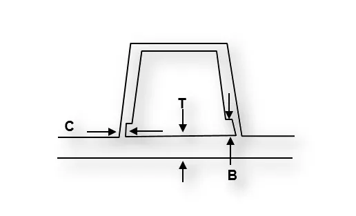
Dog house is an engineering feature used in plastic trim design. Dog houses are used as supporting feature. Dog house is a feature that helps you to avoid sink marks.
Rules-
-
Dog house wall thickness and sink saver-
“C” is where doghouse contacts backside of surface.
Dog house wall thickness at intersection of part wall (C) should be 40% or less than main wall stock (T).
Height of (B) should be between 3.0 – 6.0 mm.
-
Dog house height-
Minimum height (H) of dog house is 6mm.
Less than 6mm causes weak steel condition.
3:1 ratio of steel width to height, 2:1 is preferred.
-
Dog house width-
Minimum dog house width (X) for doghouse is 12mm.
3:1 ratio of steel width to height, 2:1 is preferred.
-
Dog house draft to die draw-
Minimum draft (D) for dog houses 1.5 degree to die draw.
If a slide is being considered, this requirement can change to 3 degrees minimum.
Tool Axis-
For the tool axis we extract all the 4 edges of the locators from the master section.
Then we create a point in the middle of the 4 edges, then we make a bisecting line between 2 edges. From doing this we get 2 lines.
Then we draw another line which will bisect that two lines and that will be our main tooling axis.
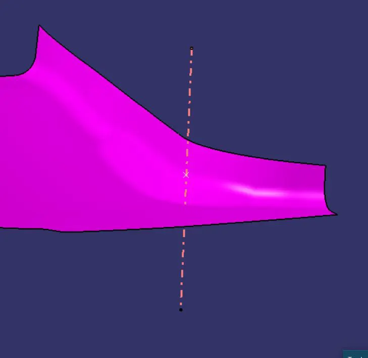
Draft analysis of Class A -
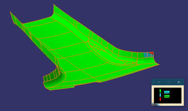
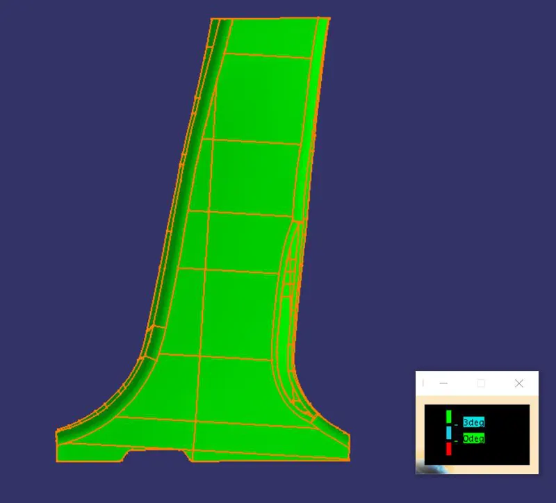
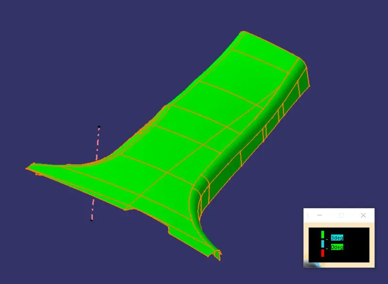
After creating a tool axis we do the draft analysis. Before drafting we have to make sure that in the view mode it is selected to the materials.
After selecting the feature draft analysis tool we drag the compass from its position to the tool axis. Then lock the compass. After that select anywhere on the component and it will give you the result.
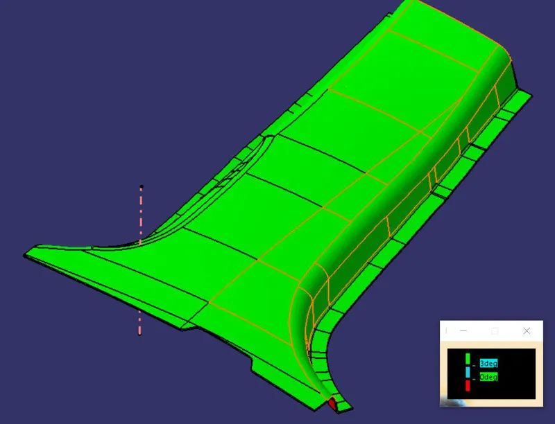
We change the minimum draft for the component to 3°.
We can use the running point option to check the angle of the component.
We can even modify the colour according to our preference.
Class B surface-
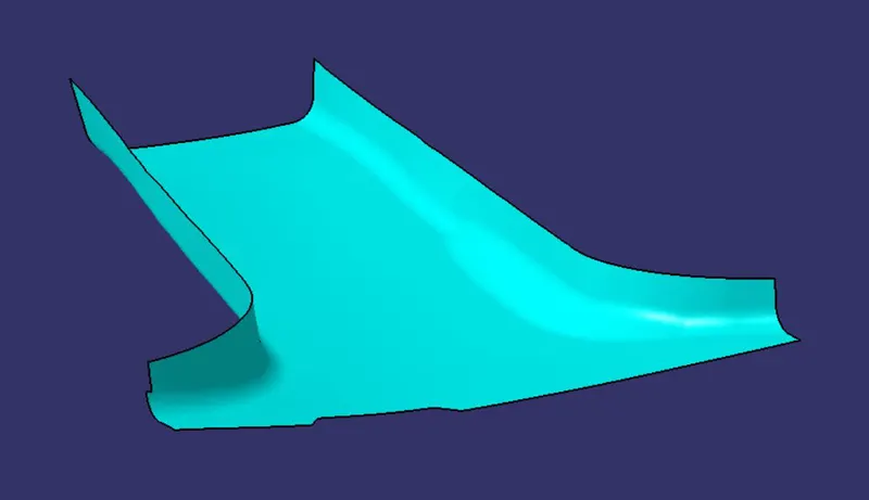
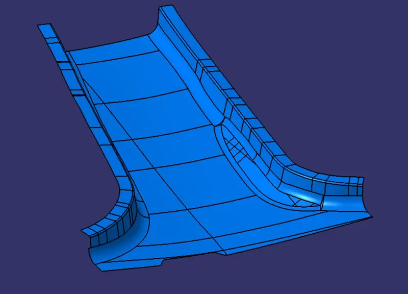
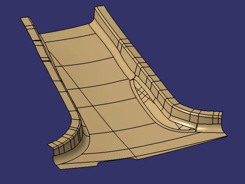
For the B surface what we usually do is extract the plain surfaces and offset it, but here since the fillet is part of the design in class A we cannot change that. So we offset the whole surface of the class A upto 2 mm. After offsetting the surface we check for any defect and if there are any we patch it up using the spline tool and multi section tool.
Flanges-
In the master section there are flanges shown. So we create the flanges using the sweep option which matches the master section for the class A surface and also for the class B.
Then we trim it with the class A and give fillet to the edges. By doing so we get a class A surface with flanges.
We do the same to the class B surface and by doing so we get a class B surface with flanges.
Class C surface-
For making the class C surface we use the sweep command with reference to the draft. On some surfaces where we cannot do the sweep, there we used the multi section tool to complete the C surface.
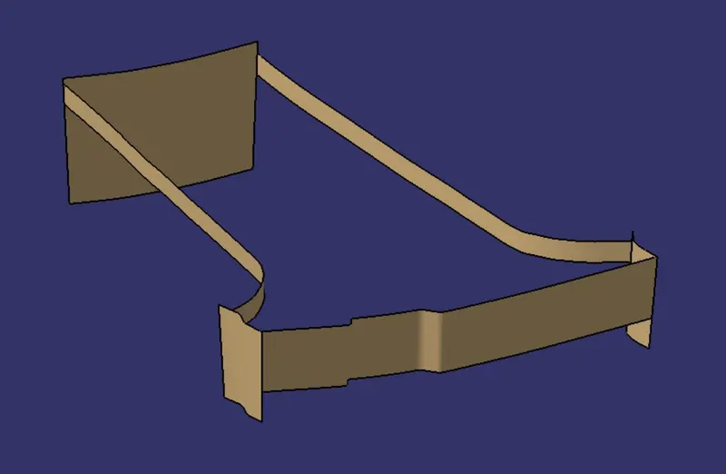
Then used the trim command to join the class A and Class C.
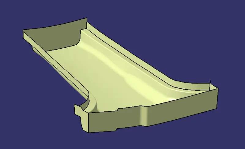
Then we again use the trim command to trim the class B with the trim of class A and class C to form a closed surface.
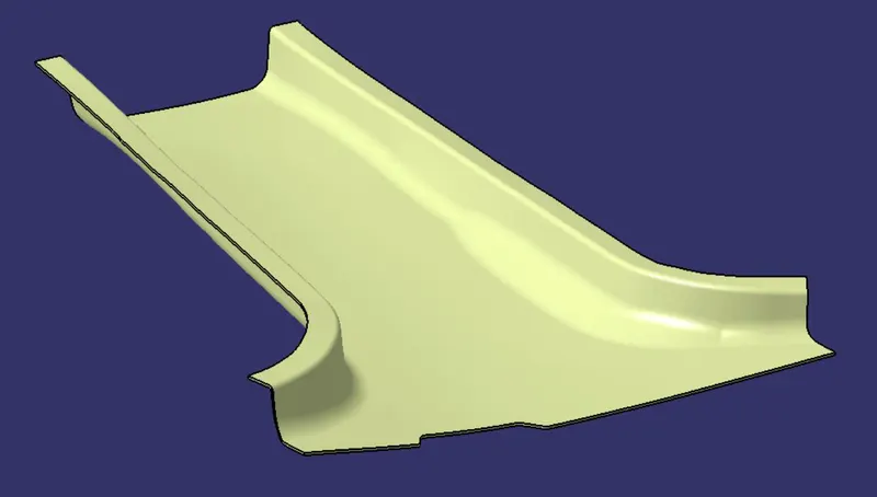
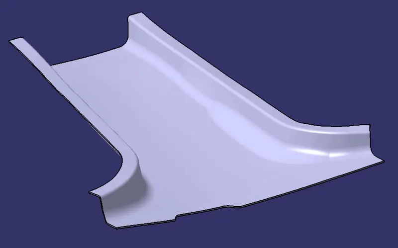
We then use the closed surface tool from part workbench to make a solid component.
Dog house -
The design of the dog house is decided by the master section. According to this we extract and trim surfaces and create the walls for the dog house. This use the thick surface tool to thicken the walls of the dog house.
According to the design rule for dog house we have to trim or remove some surface from the bottom to avoid sink mark.
We do this by offsetting the walls by 1.2mm so that we can get the wall thickness at the bottom of 0.8mm. We also offset the surface of B surface to decide its height.
Then we use the split command from the part workbench to remove the surface.
We then give draft on the inside as well as on the outside of the wall of the doghouse by 0.5° and also fillet all the edges.
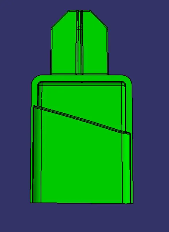
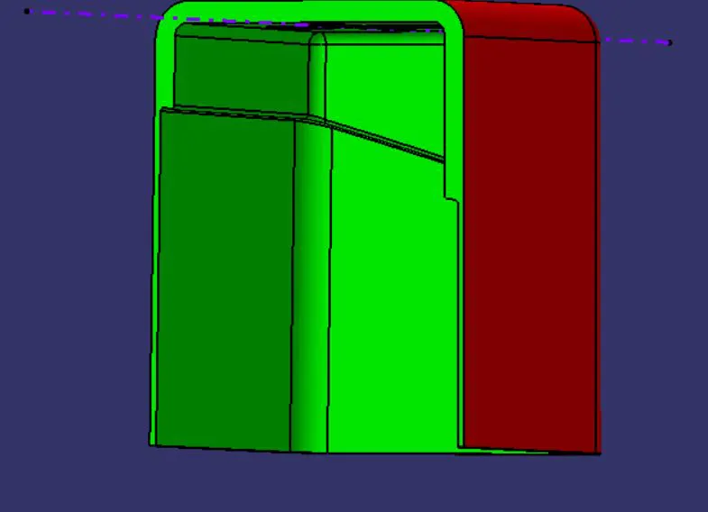
We will need a lifter axis for the lifter for the dog house. We create that axis along the plane.
Then using union trim we trim it with the B pillar body.
4 Way locator-
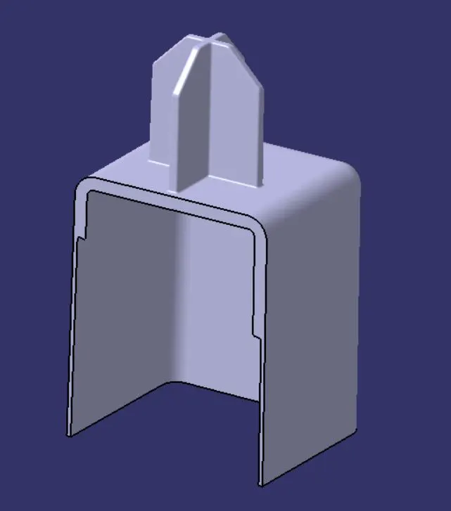
We make a sketch for the 4 way locator on top plane of the doghouse according to the master section.
Then we use the pad option and thicken the sketch and give it a length so as to form the 4 way locator. We use the chamfer tool to chamfer the corner. Then we use the draft tool to give a draft of 0.5° to the feature. Then we use the edge fillet tool to fillet all the edges. Then we use union trim to join the component with the doghouse.
We copy both the component and paste it using paste special with link and then use symmetry tool to copy it on the other side of the B pillar as well.
Ribs-
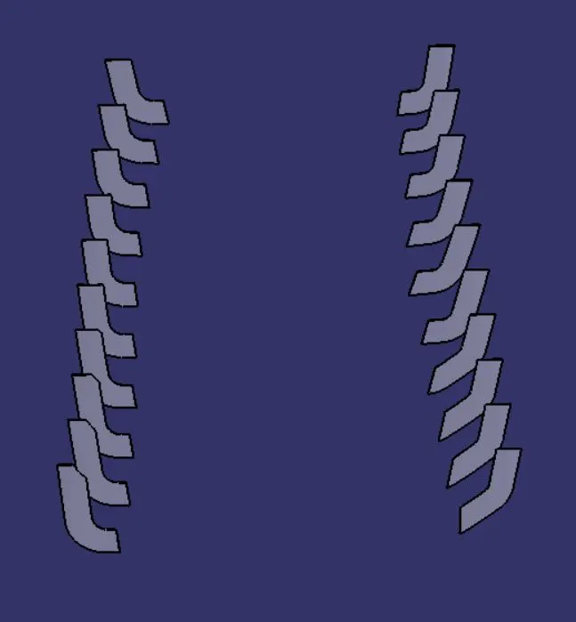
We create the sketch for the ribs and then use thick surface option and thicken it by 0.8mm according to the design rule. The space between two rib we took as 50mm. Then we draft it.
We use union trim to join the ribs with the B pillar.
Draft analysis -
Before drafting we have to make sure that in the view mode it is selected to the materials.
After selecting the feature draft analysis tool we drag the compass from its position to the tool axis. Then lock the compass. After that select anywhere on the component and it will give you the result.
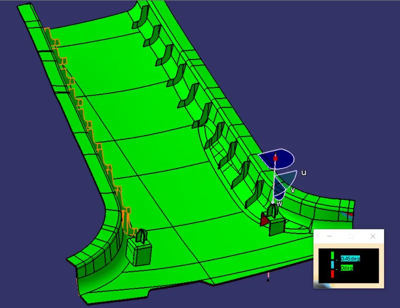
We change the minimum draft for the component to 0.45°.
Dog House lifter-
B pillar with engineering features-
CONCLUSION
From this we got to learn about the master section and also how we could make a component with the help master section which will be provided to the design engineer along with the class A surface.
We also got to learn about designing various other engineering features.