Week 9 - Project - Master Section Development
AIM: To create TOOLING AXIS, CLASS A, CLASS B, and CLASS C SURFACE and B side features by master section.
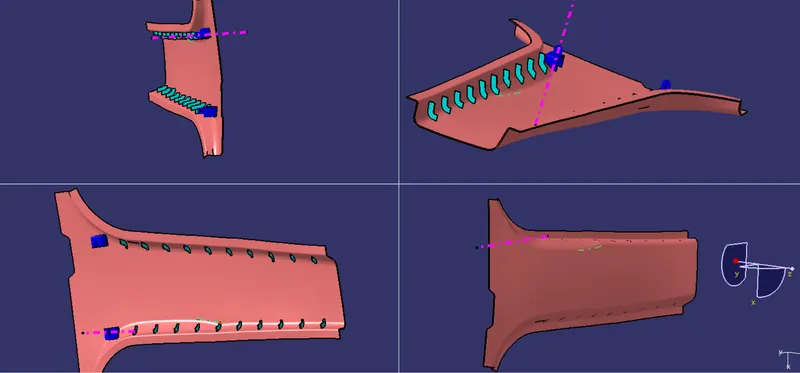
TOOLING AXIS
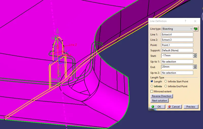
extract the master section lines.
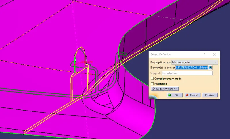
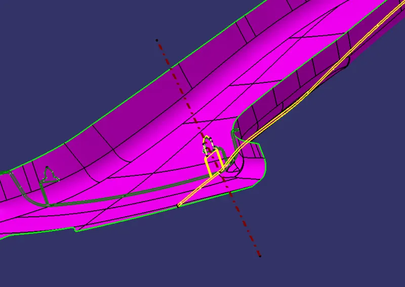
create the bisecting lines between it.
CLASS B
offset the A surface.
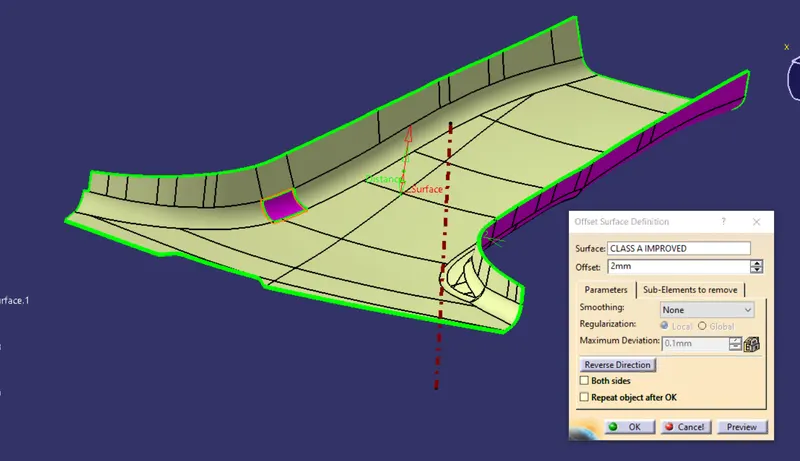
improve the surface and create the boundary and smooth curve it.
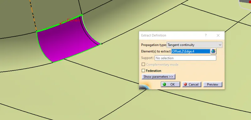
use multisection
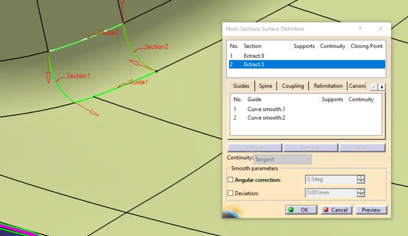
join the patch and offset B surface
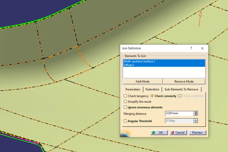
class b surface
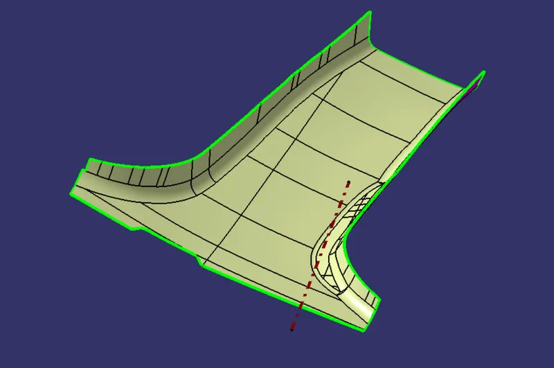
FLANGE
create a plan on multisection
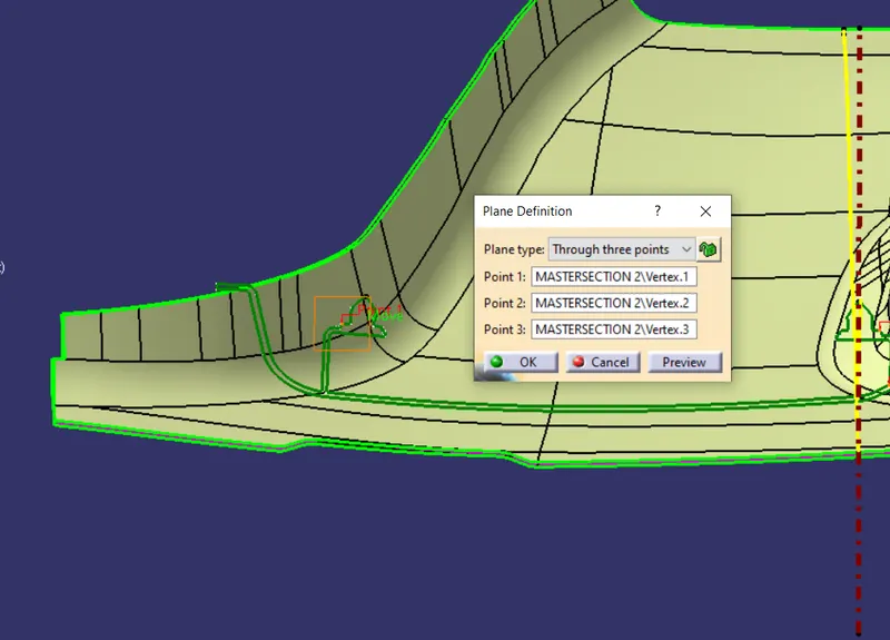
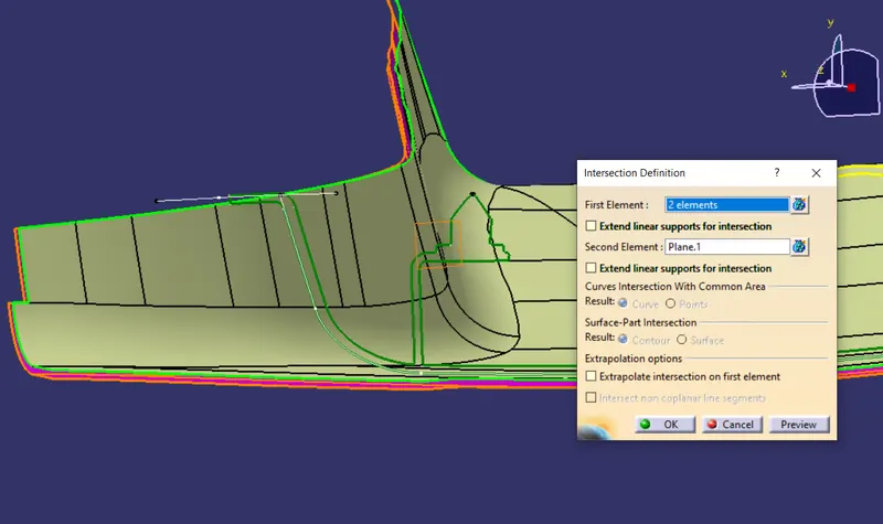
create intersection of class b surface.
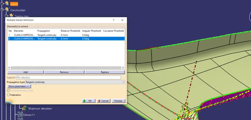
create multiple extract on the b surface
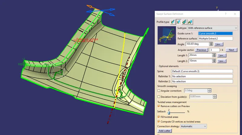
sweep the extract
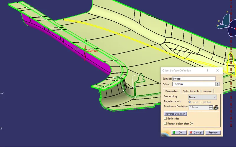
offset the sweep
create spline on the sweep
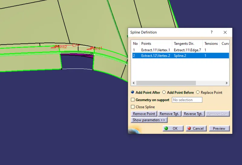
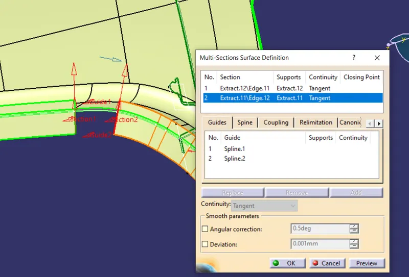
join the patch
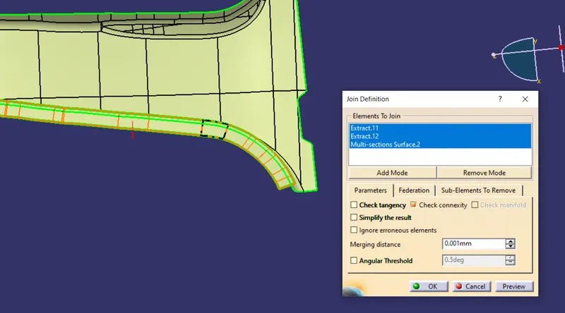
repeat it on the other side for flange 2
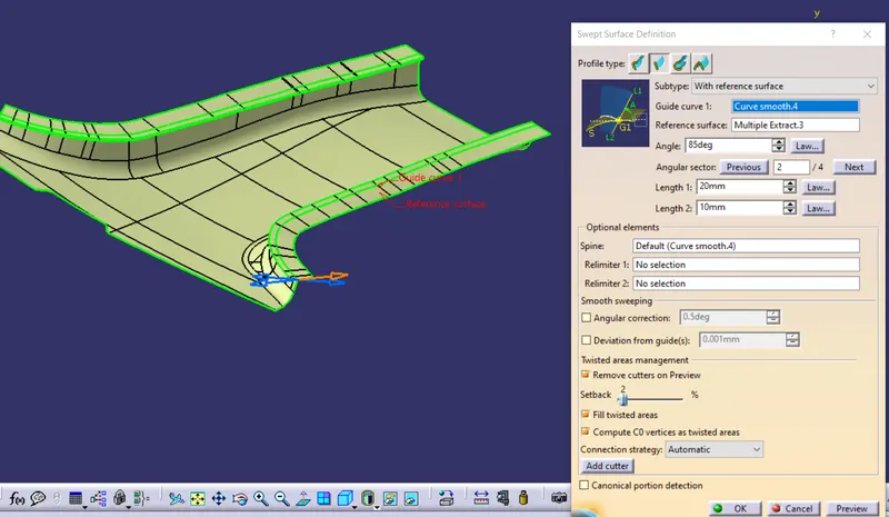
trim the class a surface with flanges
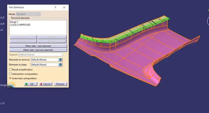
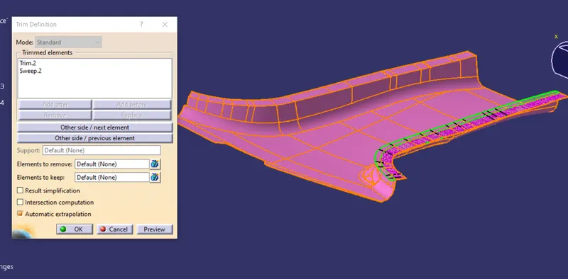
apply fillet to the flanges
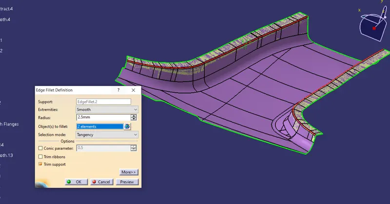
repeat the same for class b surface and trim it with the flanges
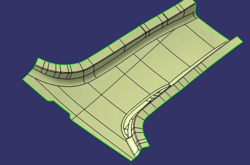
CLASS C SURFACE
create multiple extracts and sweep them.
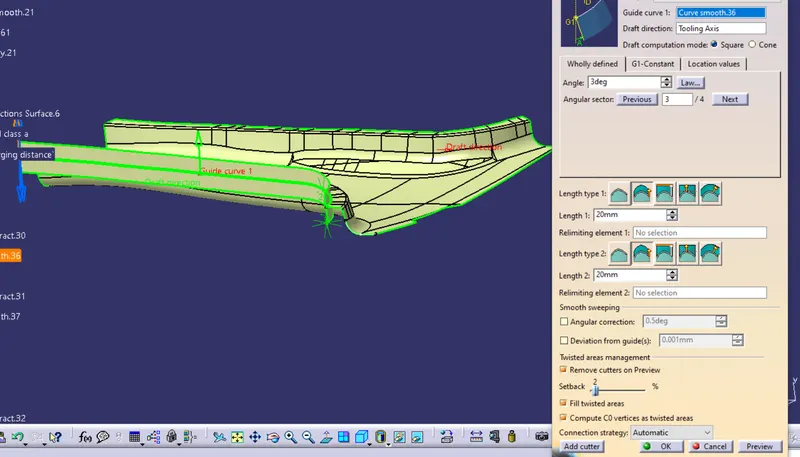
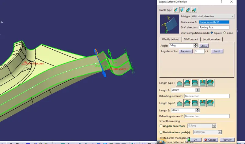
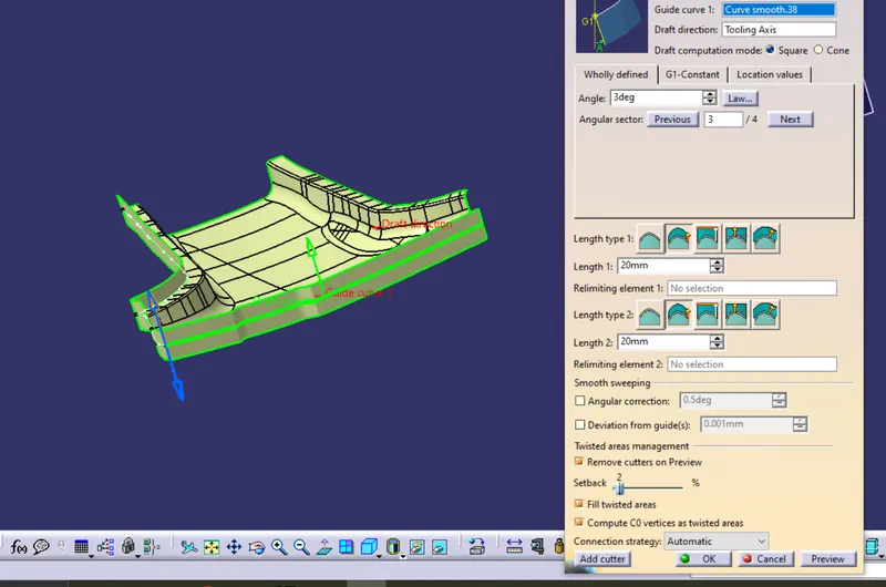
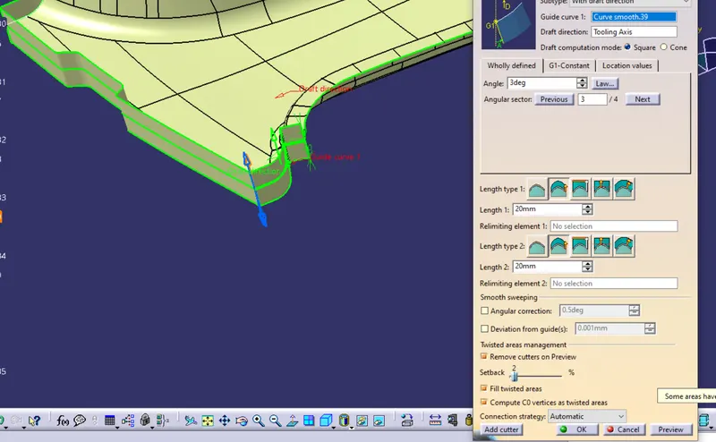
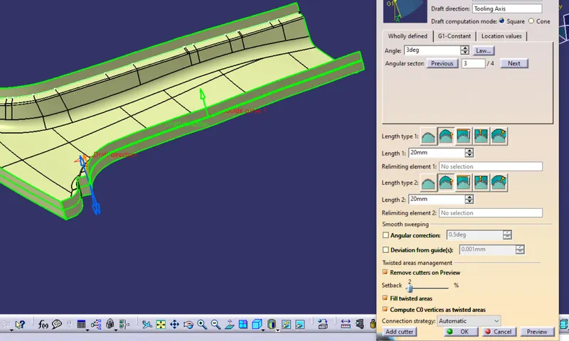
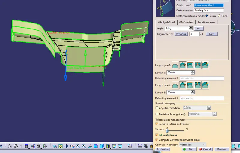
extrapolate the sweep
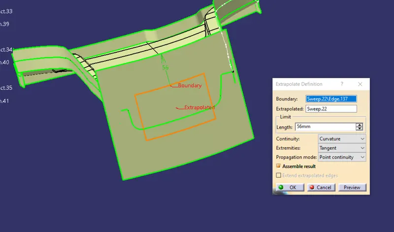
extrapolate the b surface
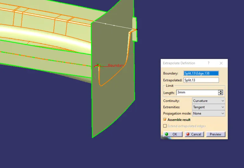
trim the extrapolated surface with the c surface.
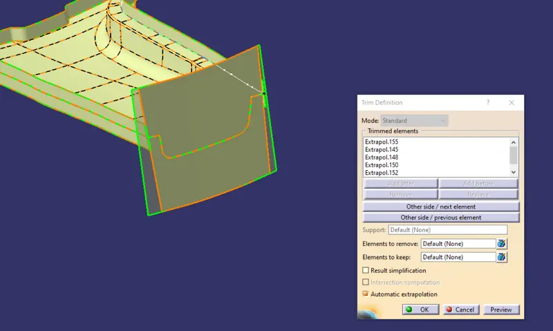
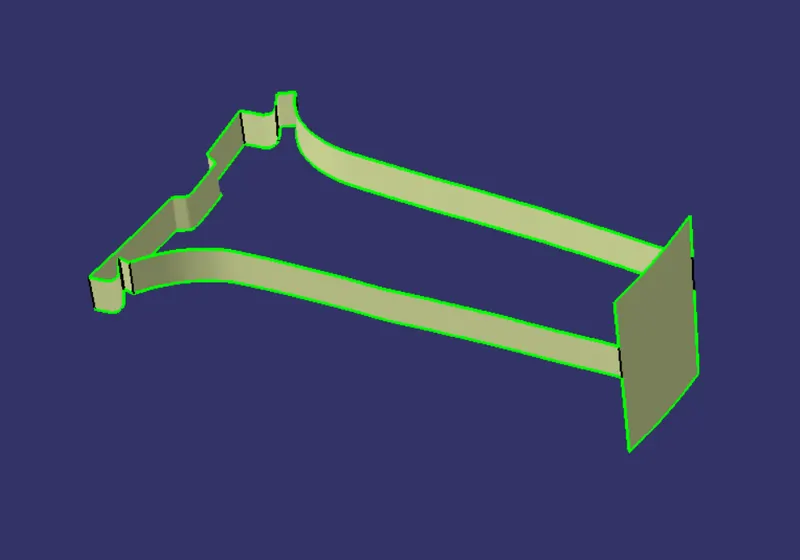
final trim
now trim a surface with c surface
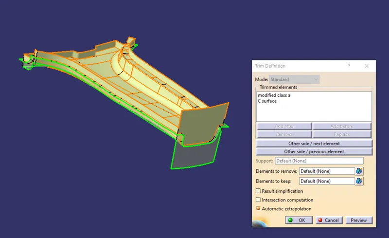
and b surface with the a and c surface
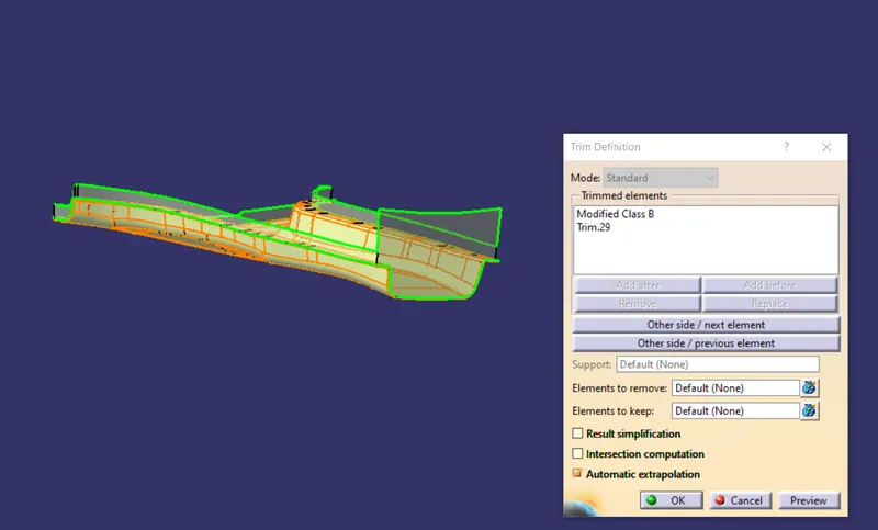
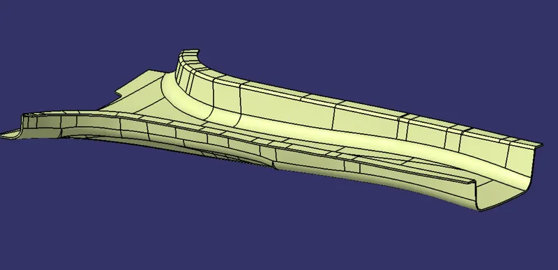
CLOSED SURFACE
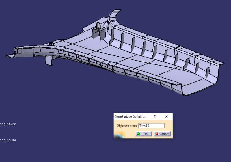
B SIDE FEATURES
DOG HOUSE
crate a plan on the multisection
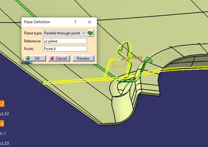
extract the master section and crate a point
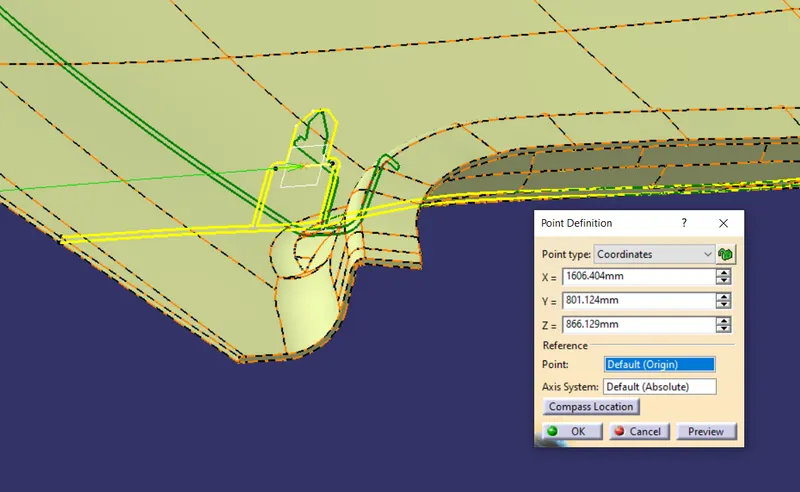
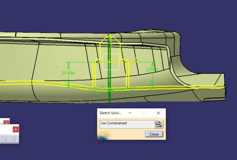
insert sketch
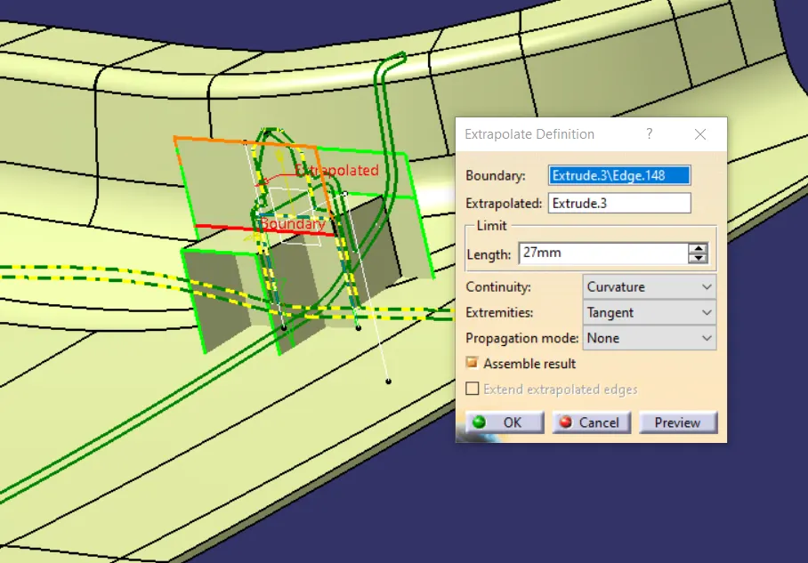
exrapolate the sketch .
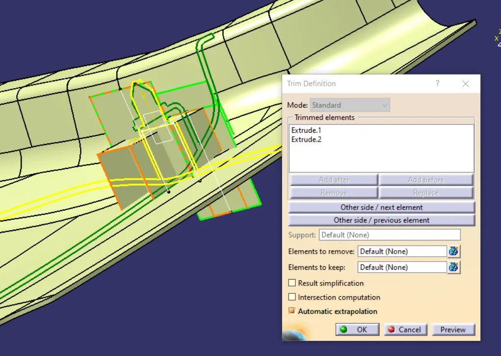
trim it
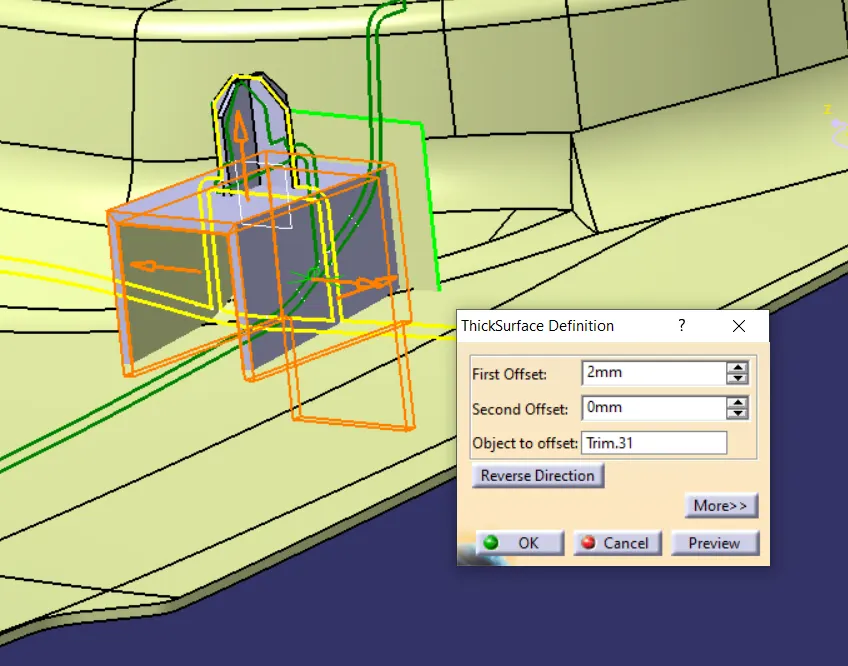
now thickness it
apply draft and fillet
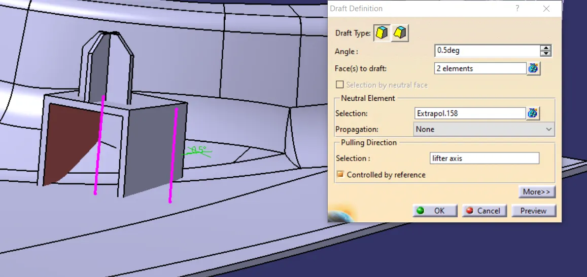
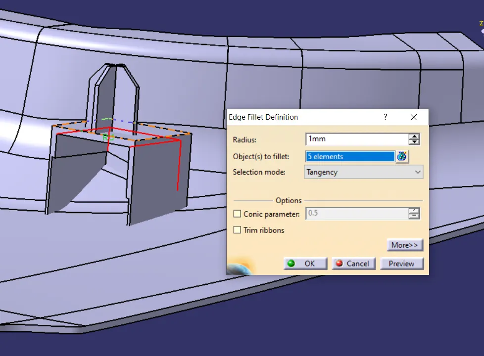
4 WAY LOCATOR
insert a sketch and iso constrain it
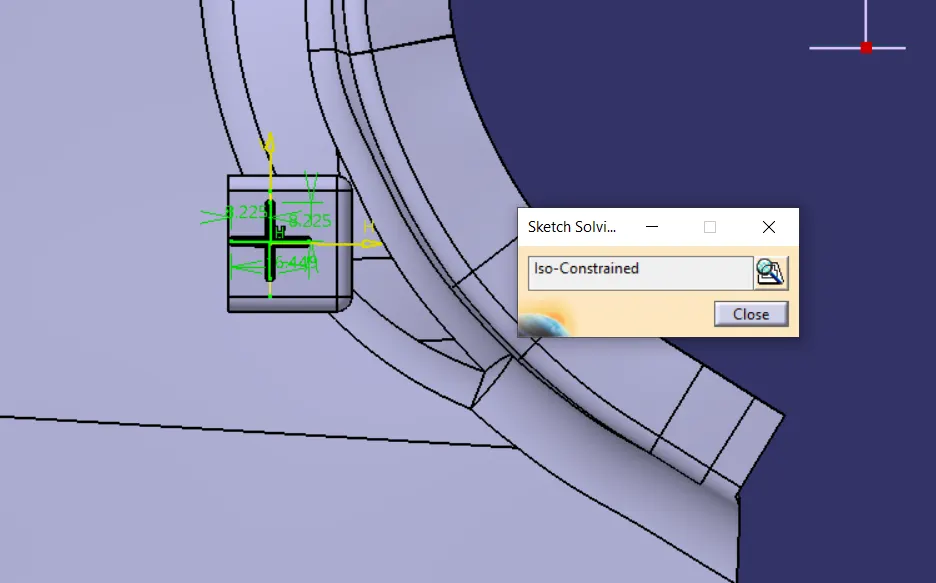
pad it
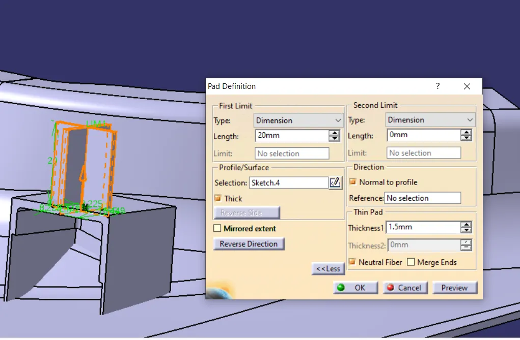
apply chamfer and draft it
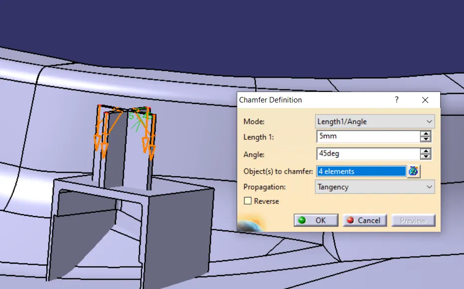
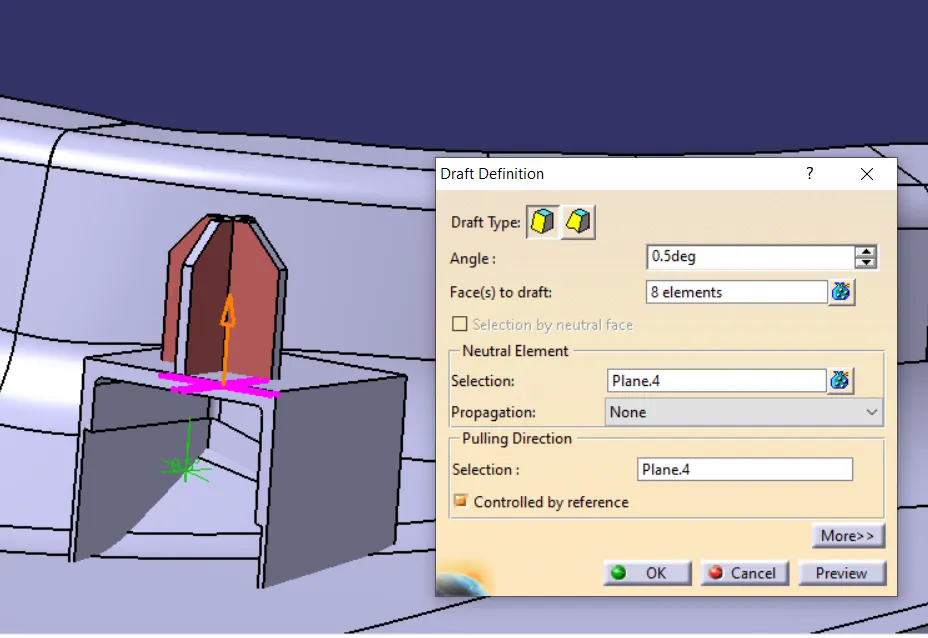
and fillet it
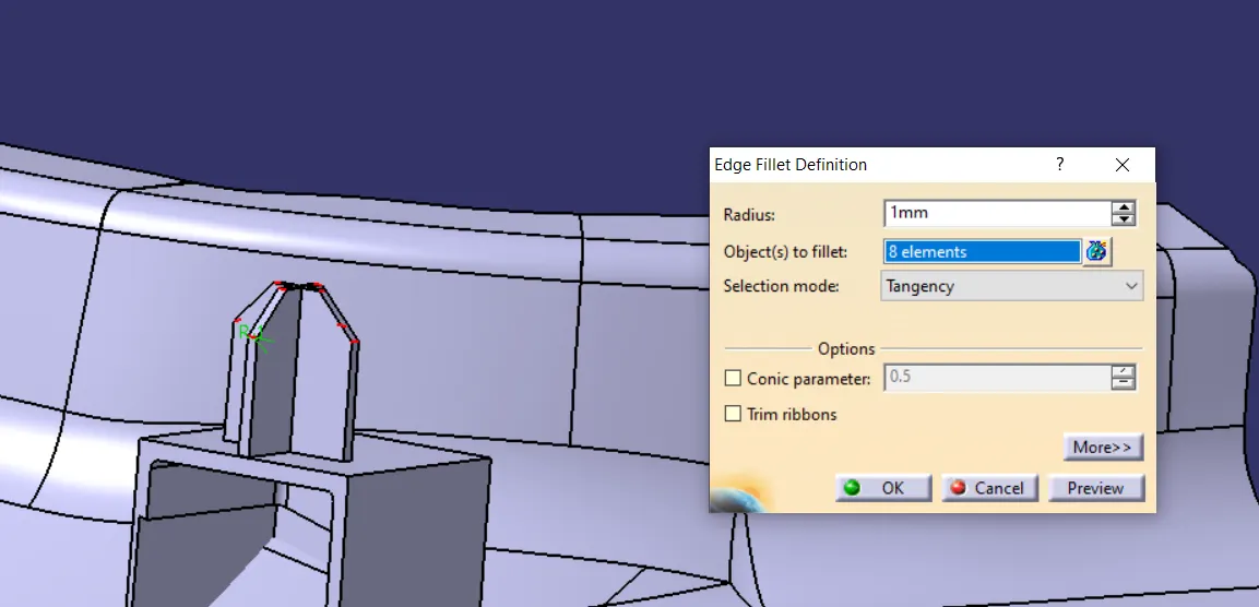
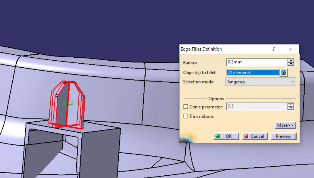
4 WAY LOCATOR WITH DOG HOUSE
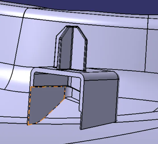
AVOID SINK MARKS
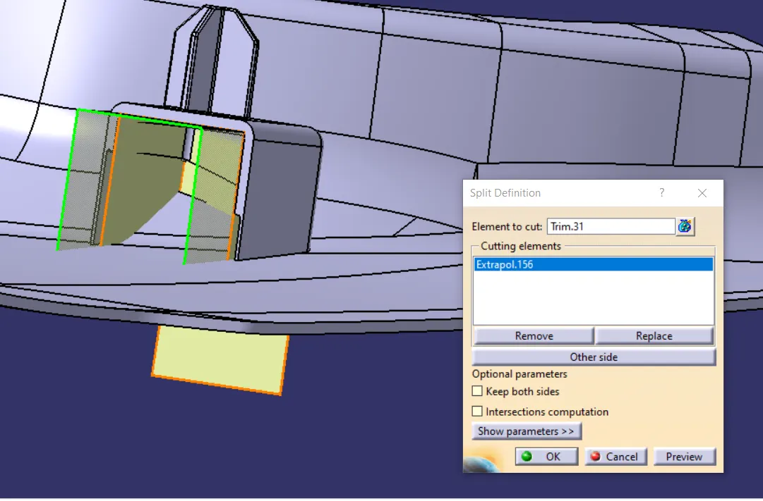
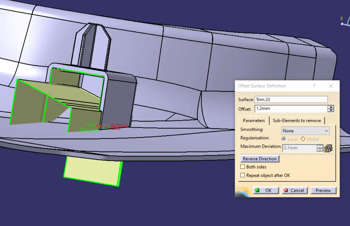
RIBS
insert a sketch and draw lines with gape of 50mm
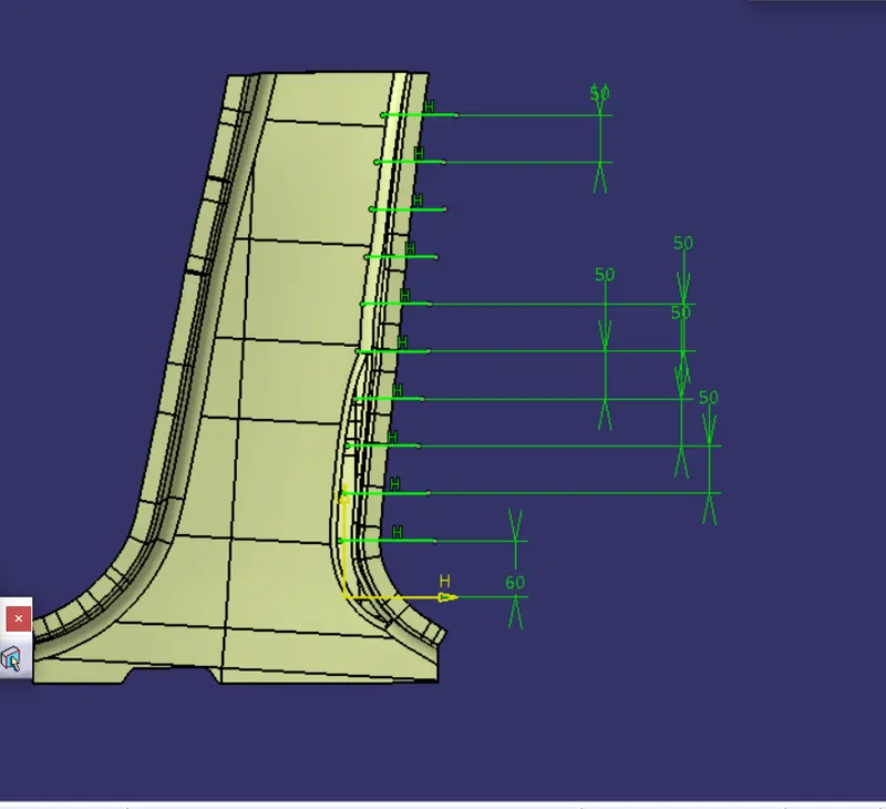
extract lines on the b side surface.
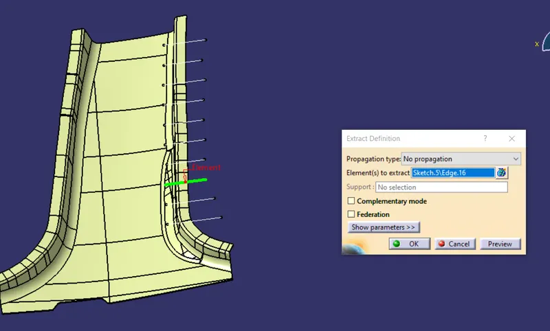
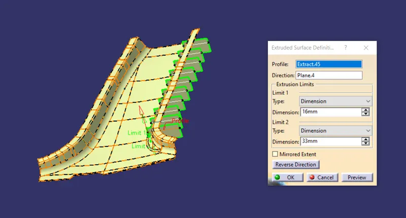
extrude each line
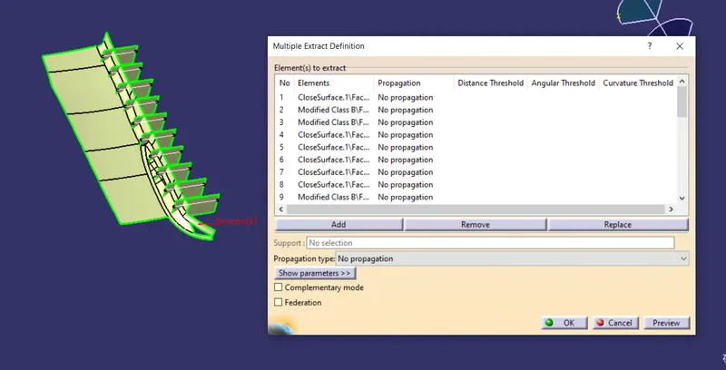
multiple ertract the base
and join it
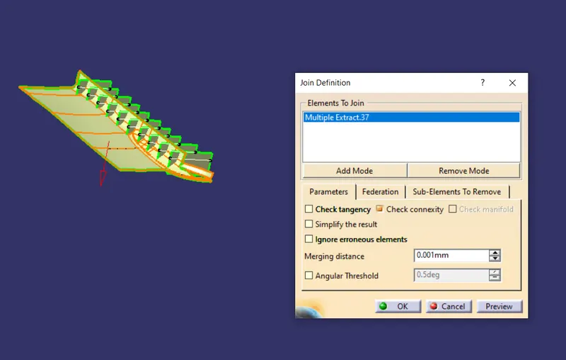
offset the base
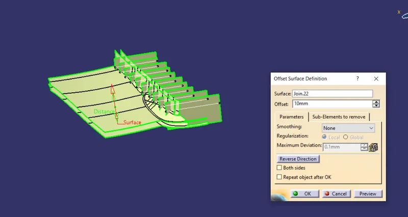
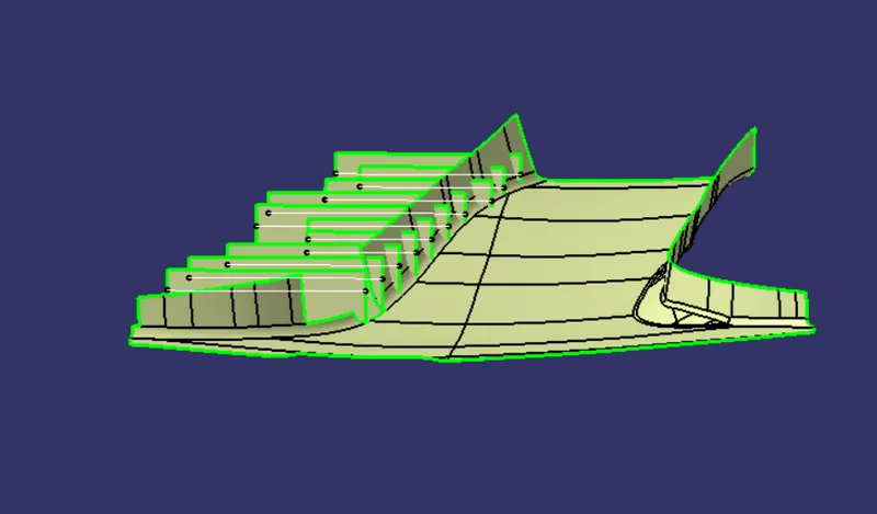
repeat the same on the other side
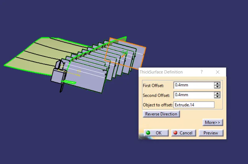
now thicken the extruded part
split itwith the base offseted
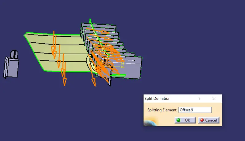
same repeat at the other side
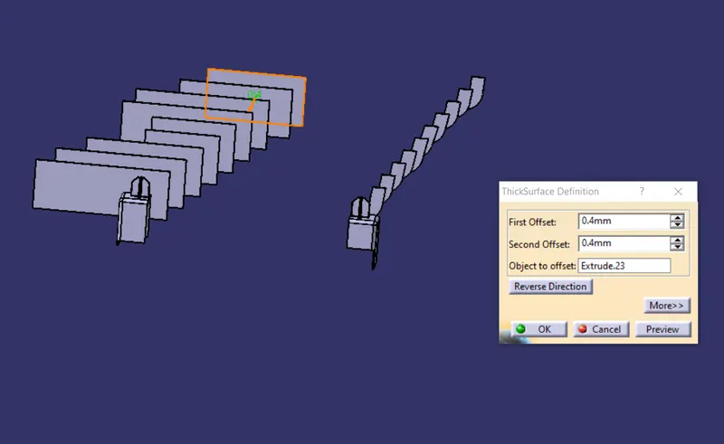
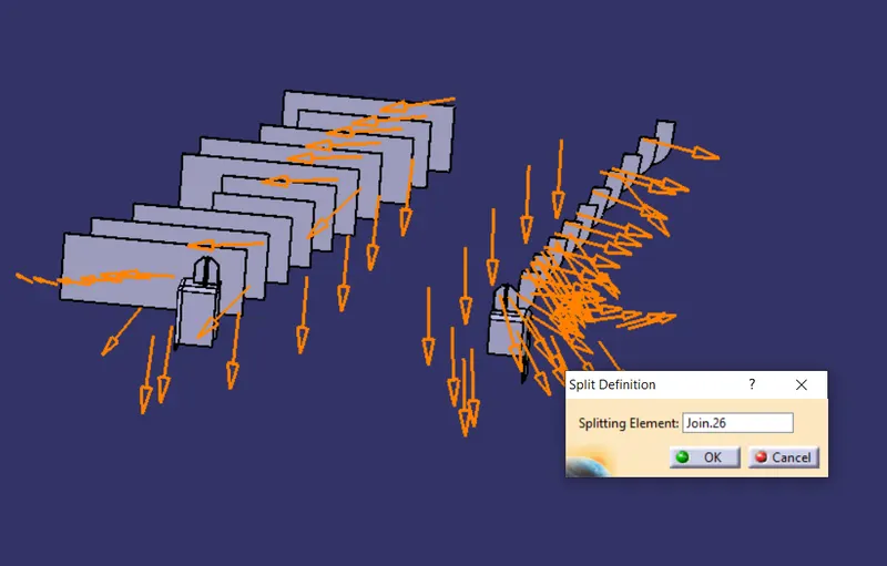
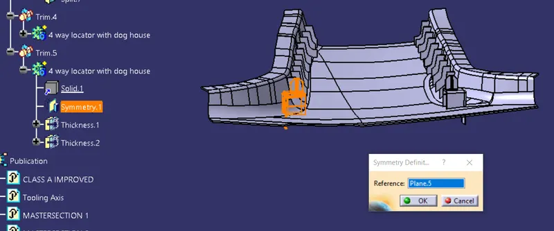
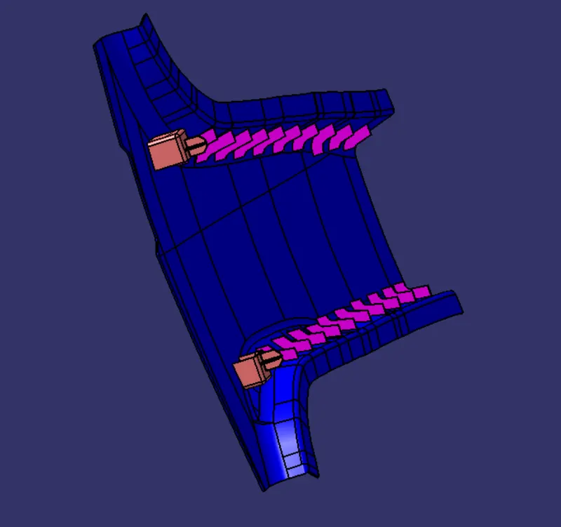
now copy the part body of 4 way loactor with dog house and symmetry i on the other side
DRAFTING
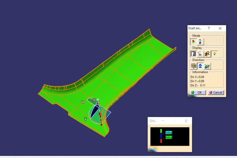
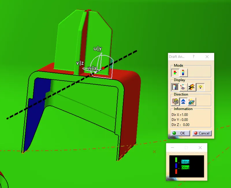
It is a tool that allows the user to ‘see’ whether the part they are designing can be removed from the tool being used to make it. In the case of plastic injection molded parts it also allows the designer to see if there is enough draft on the part to ensure that it can be correctly grained. I always use the tool with the axis direction method. Put the main axis on the draft direction line with Z being parallel to it. Select the tool then select the part body. You may need to reposition the axis again. The results window has 2 options 1 with just 3 color variants and the other with many variants. They can be edited by double-clicking on them to give you the result you desire. The colors show the different draft angles
draft analysis on class a surface
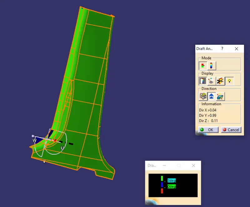
draft analysis on the part body
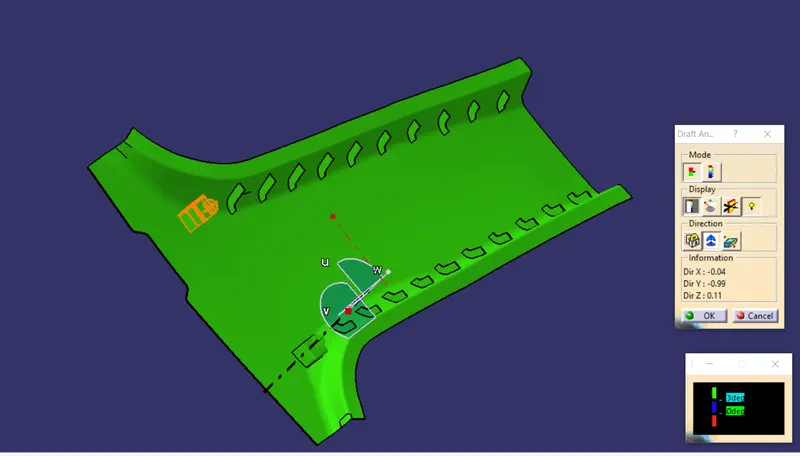
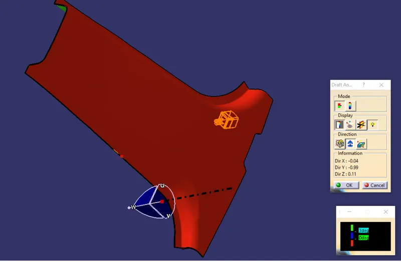
draft analysis on lifter
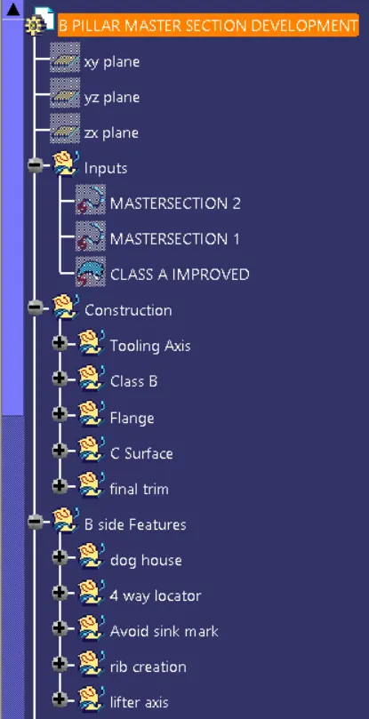
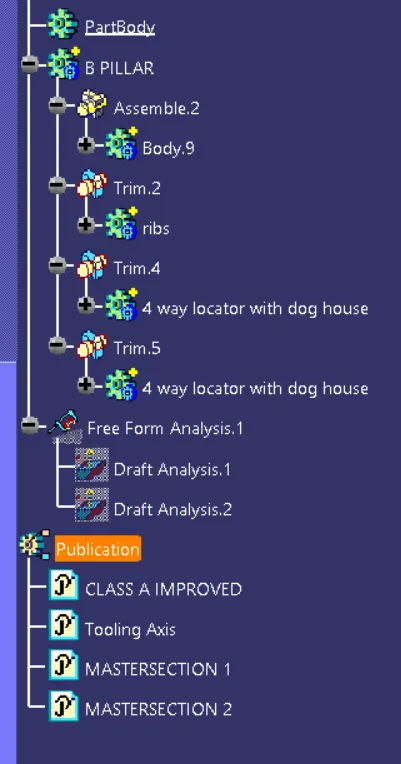
TREE STRUCTURE