Week 8 - Challenge 3 - Switch Bezel Design
SWITCH BEZEL
AIM :
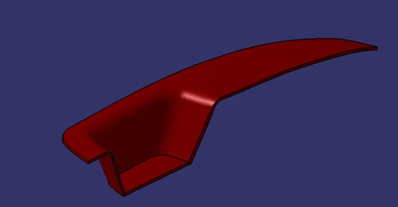
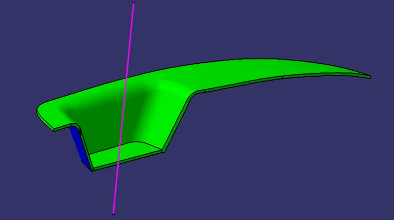
To create class B and class C surfaces from the given class A surface of switch bezel and crate tooling axis and draft analysis.
Tooling axis
When a machine with one or two rotary axes on the head is referenced by the Part Operation, you can check machine accessibility when defining the tool axis of a machining operation. The Tool Axis dialog box includes more options in this case.
STEP 1:
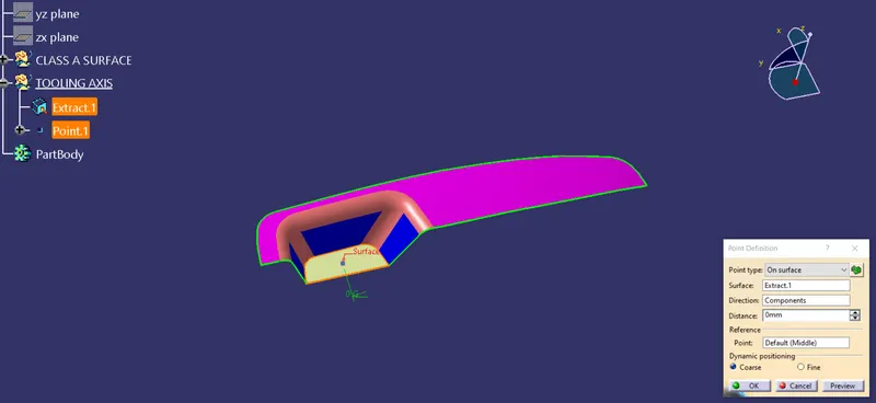
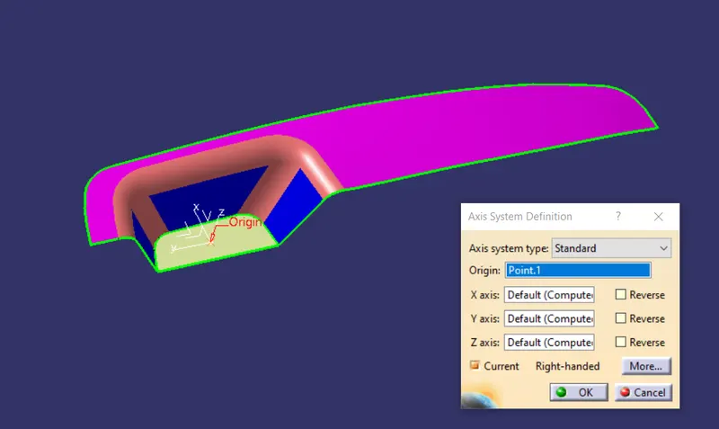
create a point in the center of the given switch bezel surface and place an axis system on the point.
STEP 2 :
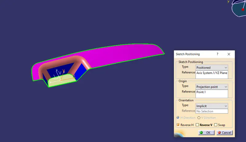
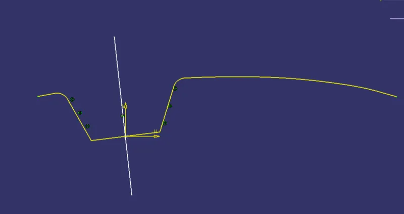
Insert a positioned sketch in the YZ plane and project 3d element of the class A surface. after that create two lines on the inclined lines of sketch, bisect both lines with line command.
STEP 3 :
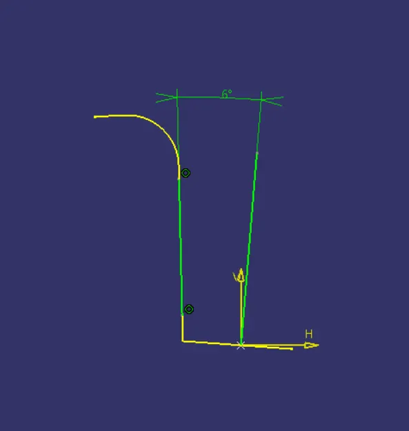
Insert a positioned sketch in the XZ plane and project 3d element of the class A surface. after that create a line on the inclined lines of sketch, bisect both lines with line command.
STEP 4 :
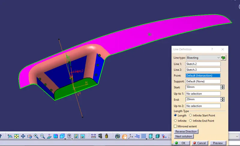
bisect both lines obtained from sketch 1 and 2, the obtained line is TOOLING AXIS.
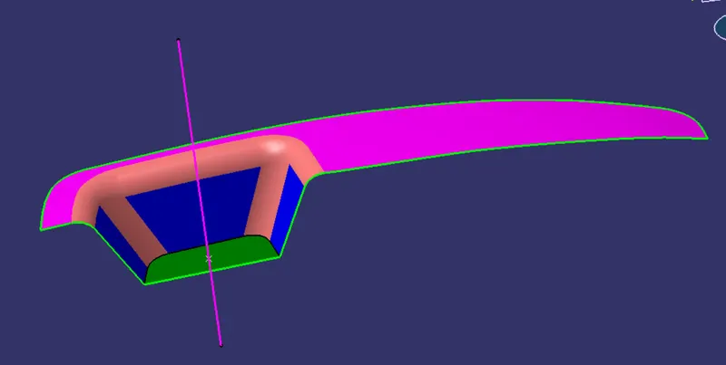
CLASS B SURFACE
STEP 1
extract the bezel rest surface from the class A surface.
now untrim the bezel rest surface.
and then off set the untrim bezel rest.
STEP 2
repeat the same processes for the walls and base of the given class A surface.
walls
BASE
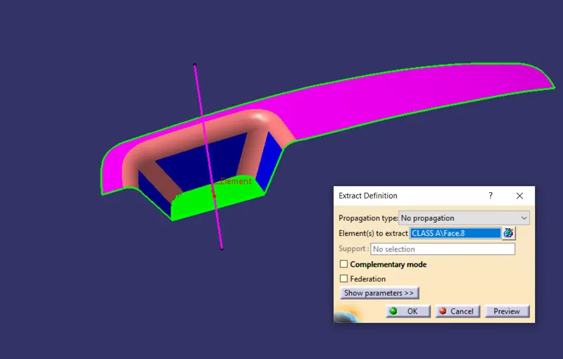
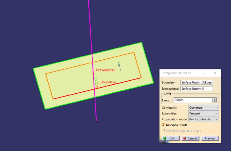
STEP 2
now trim the extra element from the offset surface to get class B surface.
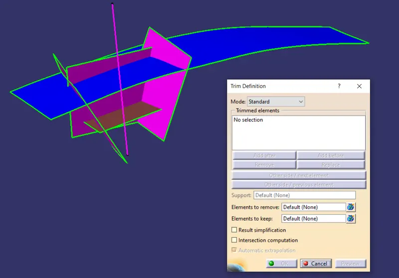
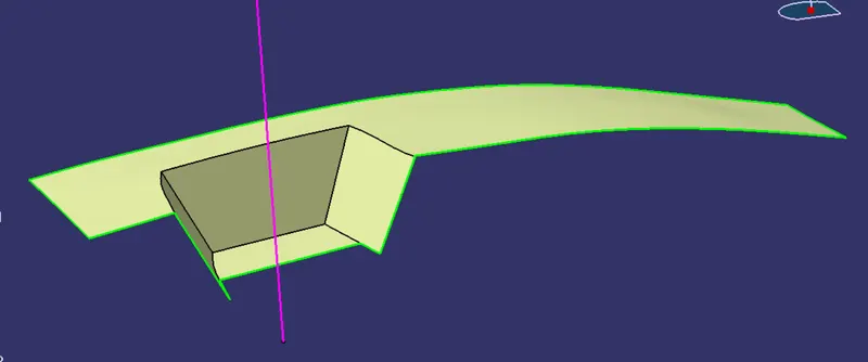
STEP 3
FILLET
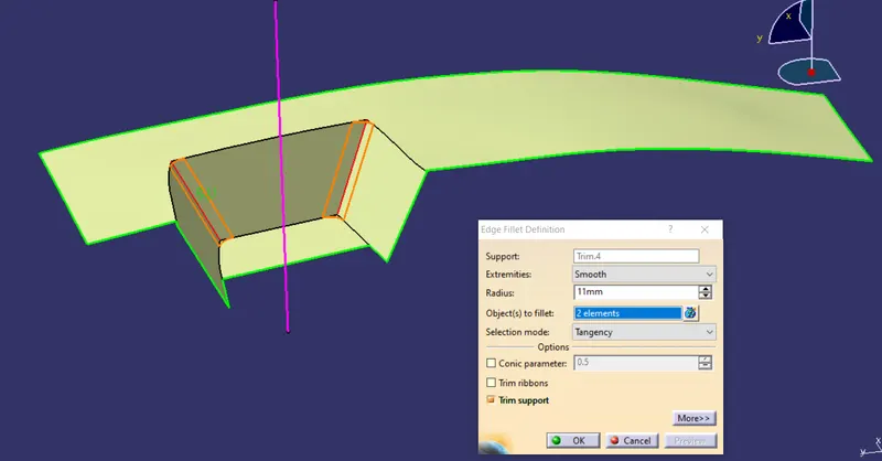
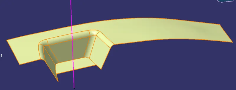
CLASS C SURAFCE
STEP 1
create the boundary of the class a surface.
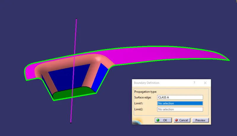
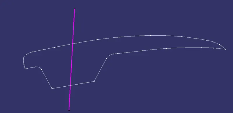
STEP 2
sweep the boundary with the tooling axis.
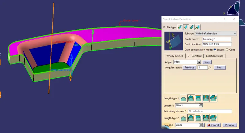
STEP 3
join the class A surface and class B surface.
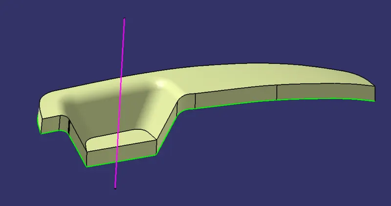
TRIM class A with class B to obtain a closed surface.
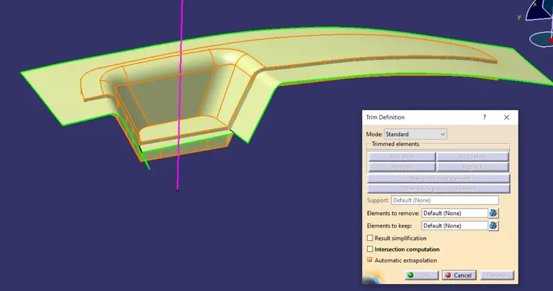
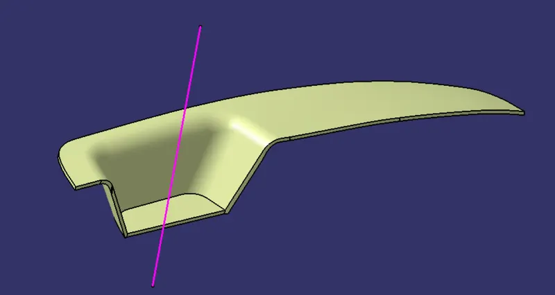
now the closed surface command from the part body to form a solid.
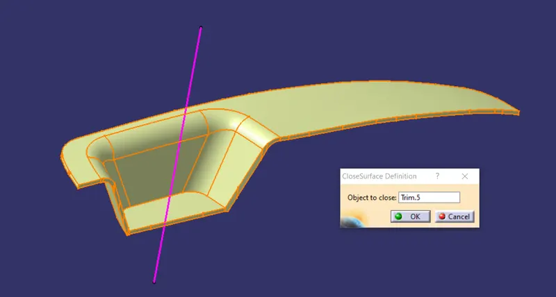
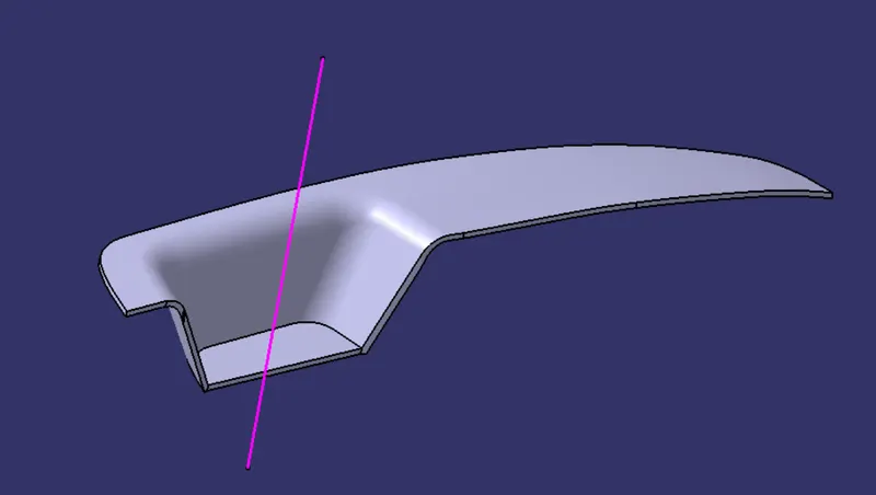
DRAFT ANALYSIS:
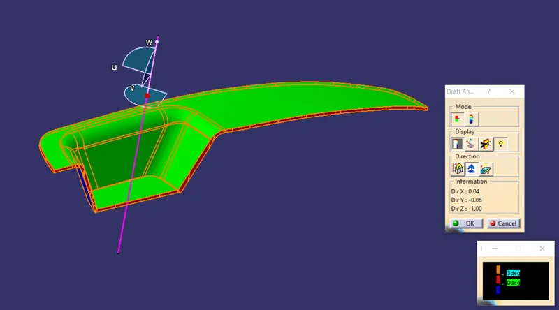
The draft analysis button within CATIA V5 will help you quickly gather the draft angle on multiple surfaces without the need for tedious manual measurements. Here is a quick rundown of how the icon works when you have a given die direction.
For the purpose of this demo, I have a part with several drafted surfaces that are oriented in-vehicle location (i.e. not perfectly aligned with x, y, or z-direction) as seen in Figure 1. The die direction is indicated by the dashed red line.
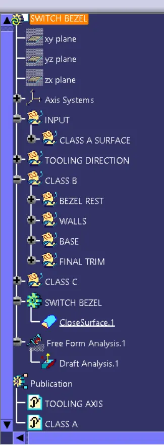
TREE STRUCTURE