Week 8 - Challenge 2 - Base Bracket Design
DRAWING 1
DRAFT ANALYSIS AND TOOLING AXIS :
AIM:
To create a tooling axis for the given base bracket surface by a bisecting method and perform draft analysis.
Tooling axis
When a machine with one or two rotary axes on the head is referenced by the Part Operation, you can check machine accessibility when defining the tool axis of a machining operation. The Tool Axis dialog box includes more options in this case.
STEP 1:
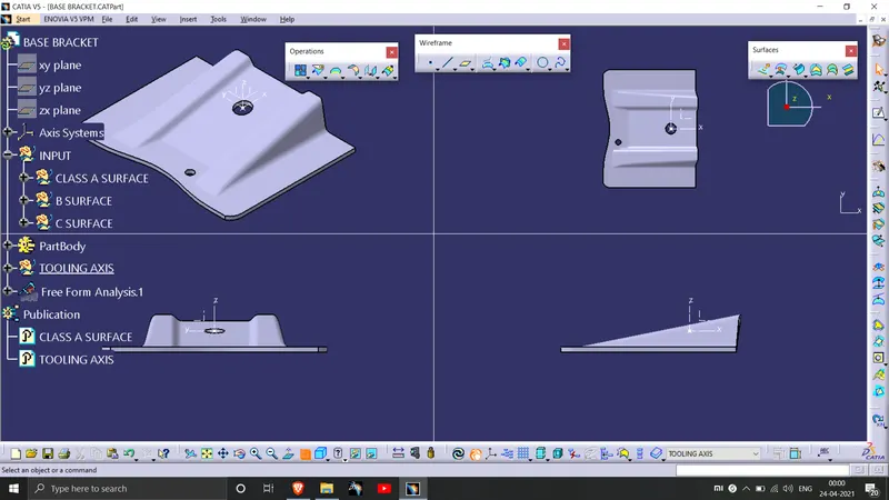
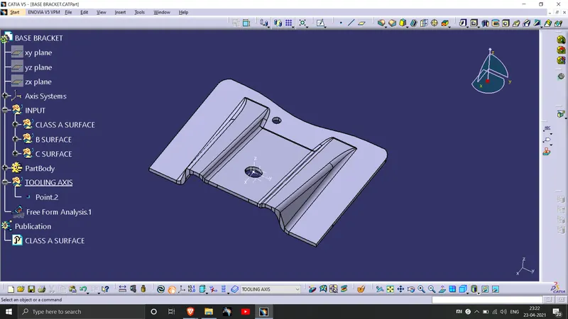
create a point in the center of the base bracket surface and place an axis system on the point.
STEP 2:
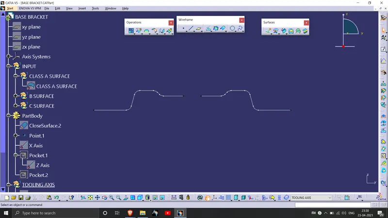
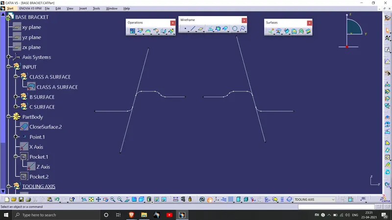
Select the ZX plane from the axis system and base bracket surface to intersect by using intersecting command to obtain the drawing as showing the image.
STEP 3:
create a line by using line command by the option of point to point on the base bracket surface on x-direction.
STEP 4:
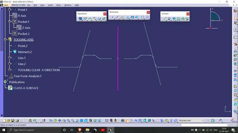
by using the two lines, bisect the lines by using a bisecting option from the line command. by this, a line will be obtain known as tooling clearing in the x-direction.
STEP 5:
select the ZY plane from the axis and fan cover surface to intersect by using the intersecting command.
STEP 6:
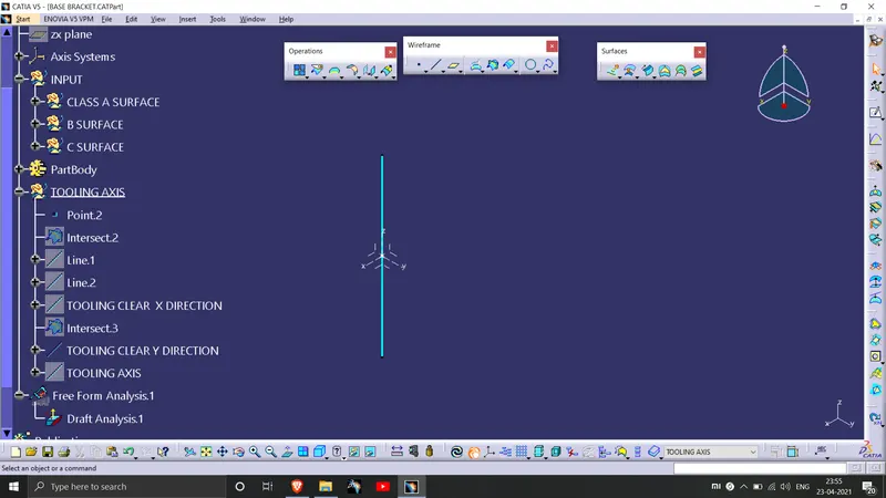
similarly, create a line on the fan cover surface on the y-direction.
STEP 7 :
bisect the lines by using the line command, a line will obtain and known as tooling clearing in the y-direction.
STEP 8 :
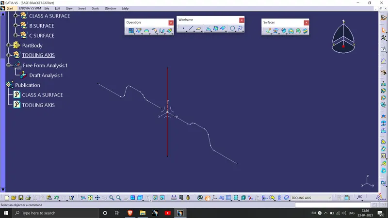
now bisect the tooling clearing in the x-direction with tooling clearing in the y-direction lines, the obtained line will be known as the tooling axis.
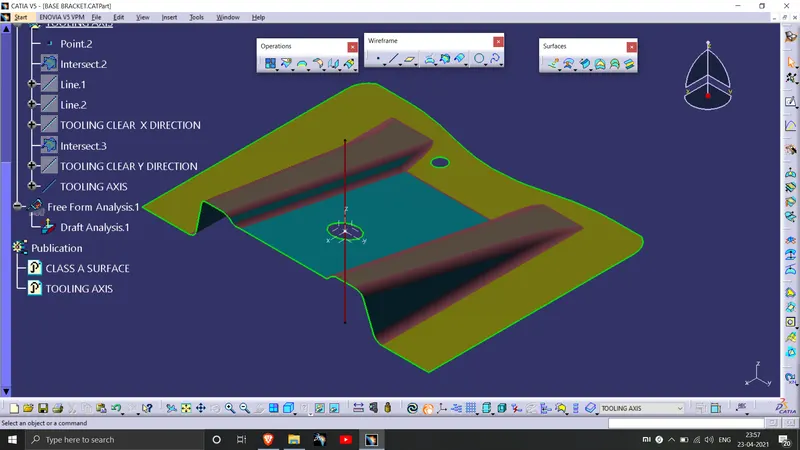
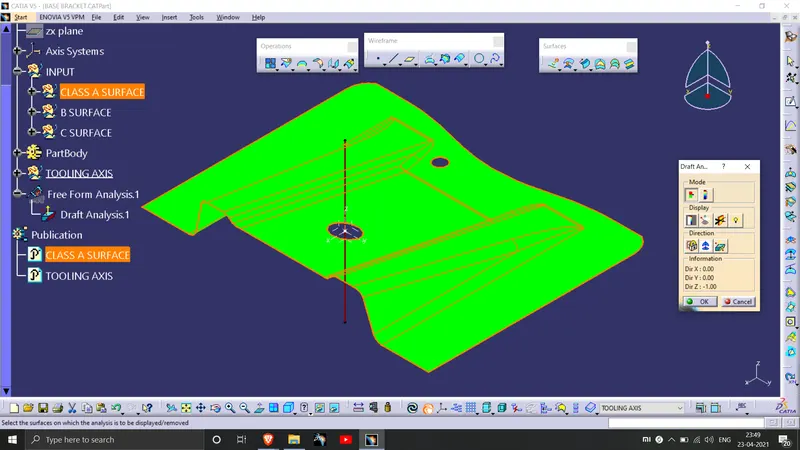
Drafts are defined on molded parts to make them easier to remove from molds. There are two ways of determining the objects to draft: either by explicitly selecting the object or by selecting the neutral element, which makes the application detect the appropriate faces to use.
STEPS
1 Select a surface.
2 Click the Feature draft analysis icon.
3 The draft analysis dialog box is displayed. It gives information on the display (color scale), the draft direction, and the direction values.