Week 9 - Project - A pillar Design with Master Section
Draft Analysis
Draft Analysis is used to analyse whether given product model is manufacturable or not. There is at least some minimum Draft angle should given for each and every product, so that the mould and part making minimum point of contact when the ejection time. It also reduces the part getting affected by the mould.
Here is the complete list of steps involved in Draft analysis for given model.
Class A Surface:
Procedure for creating draft analysis:
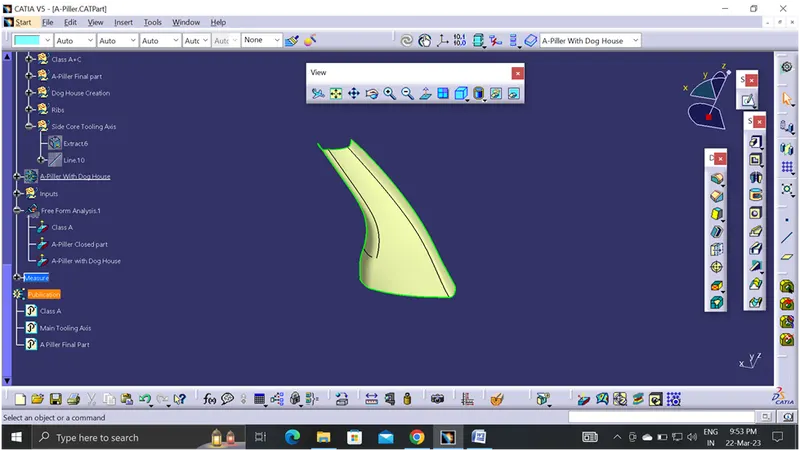
In the given class surface, have to check whether the given class a surface to clear the draft analysis, so that we have to decide whether the given product is manufacturable or not.
Creating a Tooling axis is mandatory for checking the draft analysis. On the reference of the Tooling axis only our draft analysis should perform. For creating tooling axis first analyse the given part in X, Y & Z view point and decide the maximum possibility to create the given part.
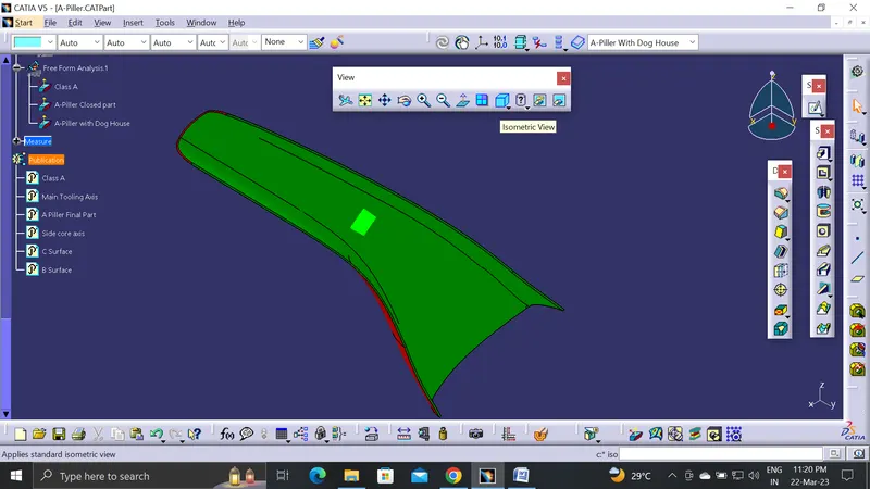
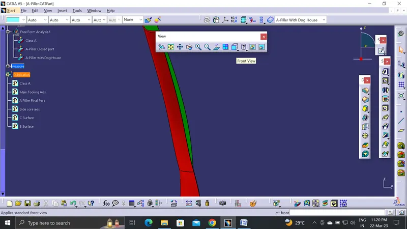
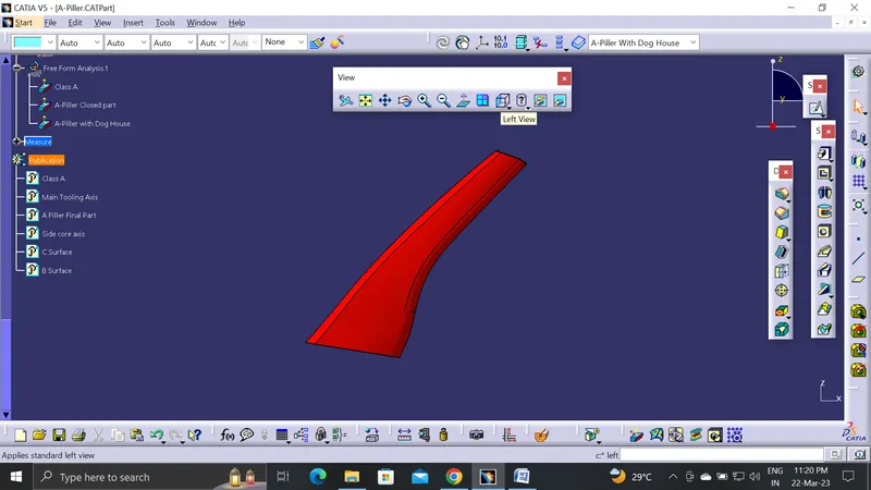
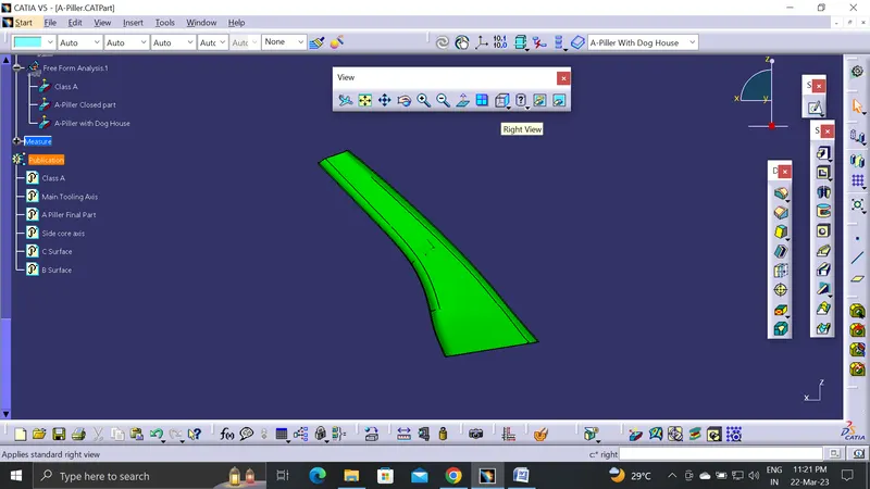
Step 1: checking the possibility of tooling axis in X, Y & Z direction.
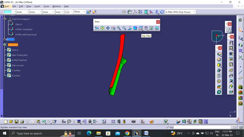
In X – Direction, Maximum part should be producible but side wall not visible clearly.
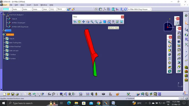
In Z – Direction, the part looks not a clear dimension so the part should not manufacture under this condition.
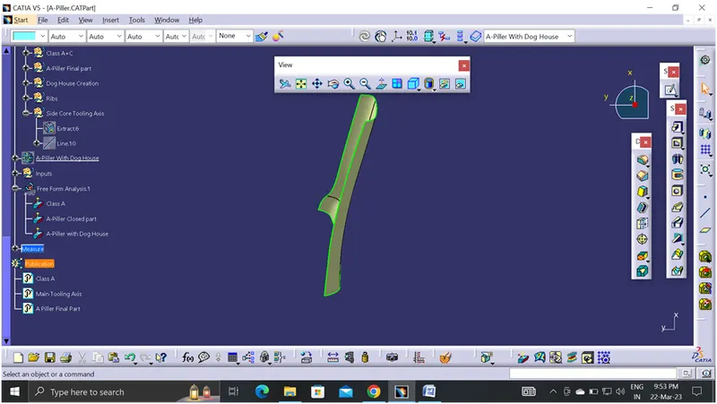
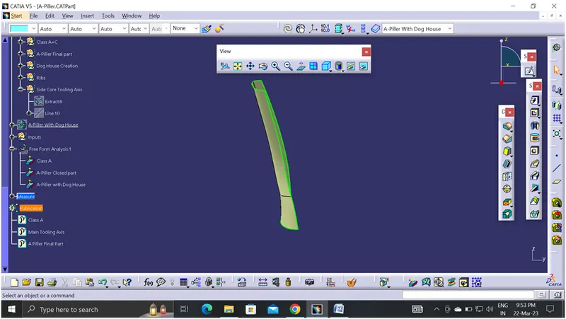
In Y- Direction, it's clear to see all the dimension and proper structure of the part.
Tooling Direction: "Y"
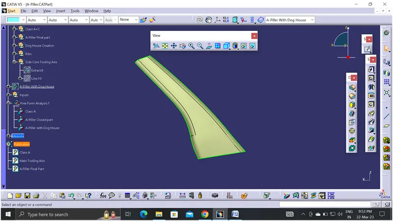
Step 2: To Create a Tooling Axis
In this particular challenge we have master section. So based on the master section we have to create tooling axis.
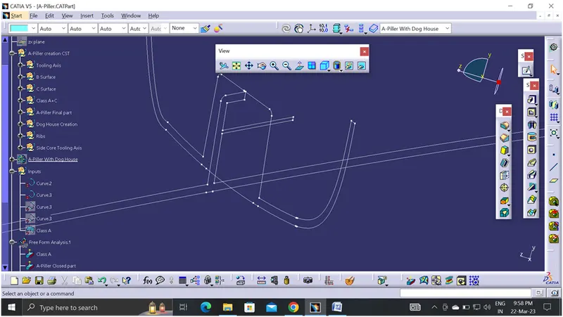
In that master section take a point from reference once pick the point make them as isolate and reorder the point as Co-ordinate. So that in case of future the master section deleted the points still exist.
On the reference point create a line and using bisecting method select the line and found main tooling axis of the component
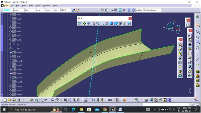
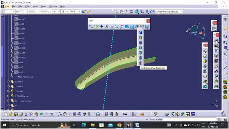
Step 3: For creating the draft analysis, first select the "Customize View Parameters" and select the "Material" option
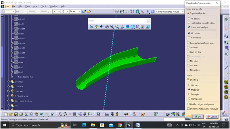
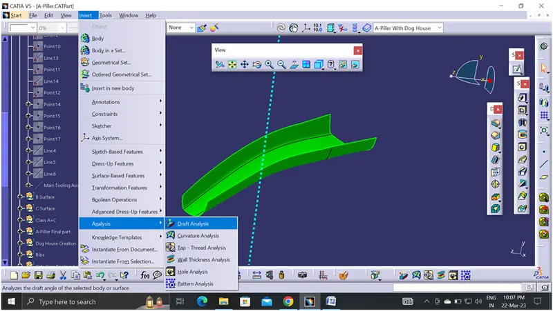
Step 4: Select the Insert > Analysis > Feature Draft Analysis
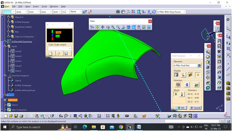
Step 5: Click the "Compass" icon and drag the compass on the Tooling axis and locking it. Make the draft angle as 3 deg. If the Draft angle is more than 3 deg. It shows a Green colour and 0 deg it shows in Blue colour. If the Draft angle is less than 0 deg its shows in Red colour.
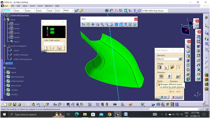
Step 6: Finally our Class A Surface pass the draft analysis test at an angle of 3 degree.
Step 7: Creation of B surface, first we offset the Class A surface at a distance of 2.5mm. While offsetting some portion are missing. We recreated the parts using sweep command.
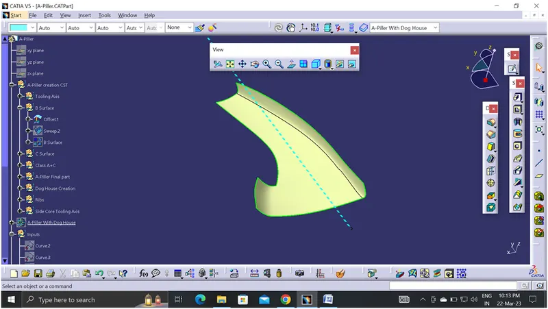
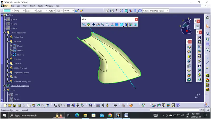
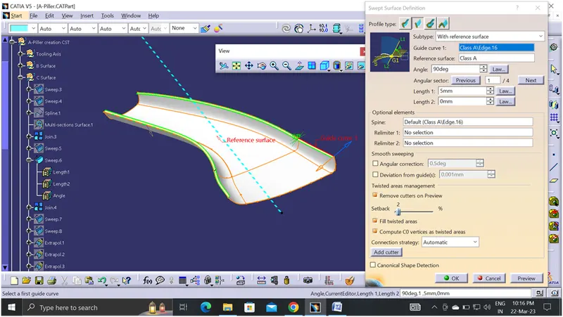
Step 8: Now creating the C surface, Take a reference boundary option from the A surface we use sweep command and using reference surface method we created the C surface on both long side of the part at an angle of 90 degree
Then comes to the sorter edge these edge perpendicular to the tooling axis, so this time using draft direction method angle of 3 degree created the c surface.
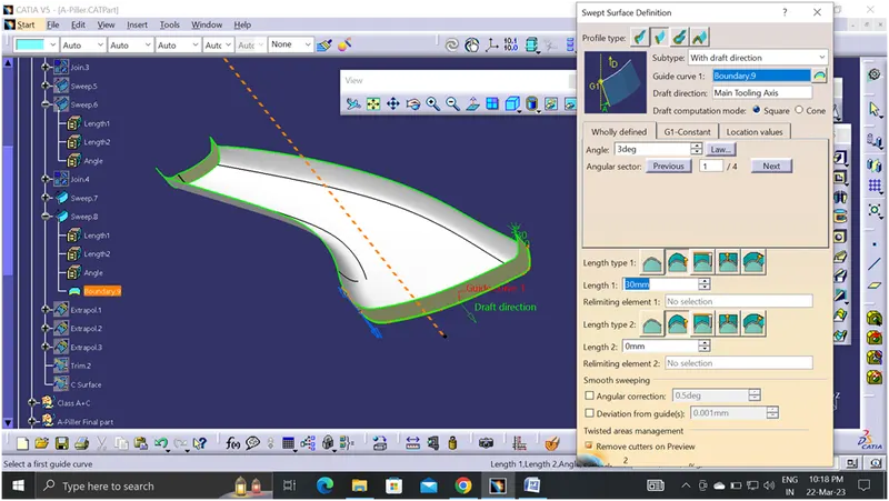
Then extrapolated some edges of the sweep and trim it to complete the C-surface.
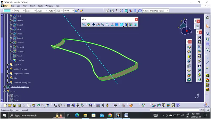
Then join the Class A with C surface. one corner is not perfectly connected using extrapolated command to solve the issue.
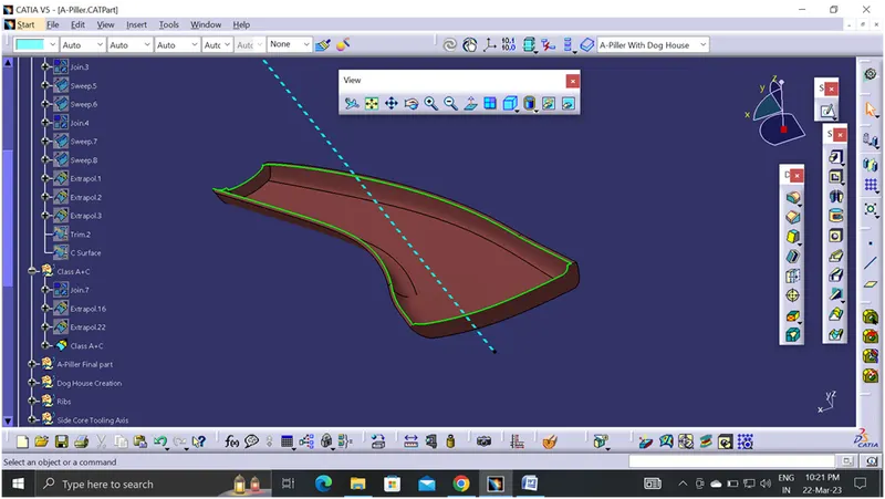
Step 10: Now going to trim the Class A+C surface with B surface. One corner is not perfectly connected using extrapolated command to solve the issue.
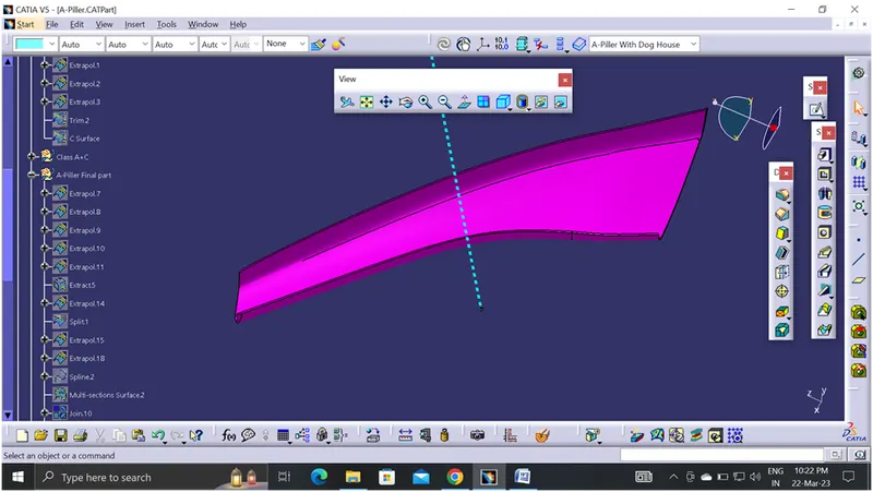
Step 11: Same draft analysis procedure is follow the final closed part (A-pillar)
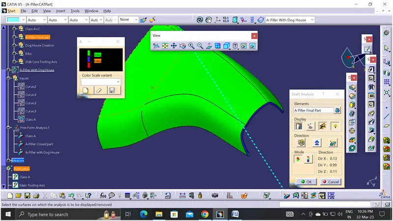
The sweep we using as "draft direction method at an angle of 3 degree". Hence some of the portion of C is Blue Colour. But when we give 2.9 degree as draft angle it's clear.
Step 12: Create a body and using part workbench using close surface command select the A-Pillar trim surface and make it as part body.
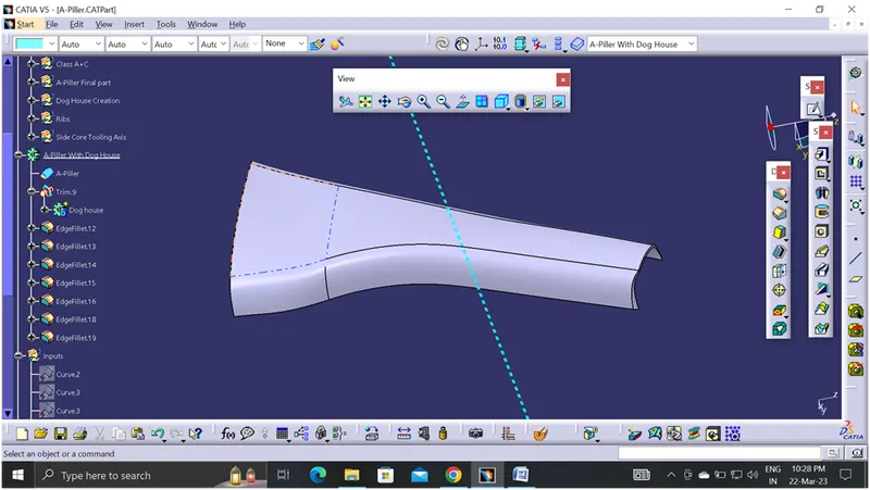
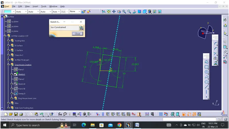
Step 13: Now creating the Dog House as per master section.
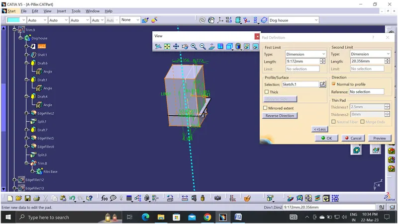
Step 14: Using Pad option as per master section data.
Step15: Using shell command removes the side wall and bottom wall. Draft the outer surface as 1.5 degree and inner surface as 0.5 degree.
Now create the side core axis using existing point and plane create a line name it as Side core axis.
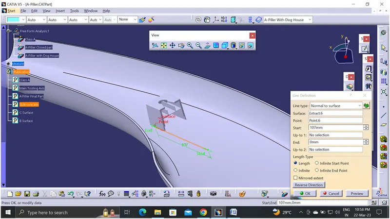
Extract the B side feature of the a-pillar and offset at a height of 5mm and offset the side wall of the dog house 1mm outside. Then creating edge fillet radius is 0.25mm which is minimum range. Outside edge is 1mm.
Now create the push pin hole for top of the dog house. Using Sketch create the Pushpin diagram and using sweep command then split the dog house in the sweep command.
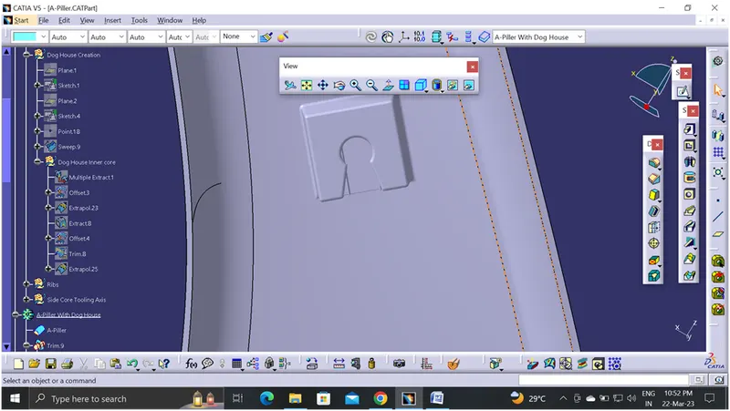
Step 16: Now going to work on the inner side of the ribs. Same that refers the master section and creates the sketch and pads it. Union trim option via trim the rib and placed inside the Dog house.
Draft all the edges of ribs using side core axis and fillet is given.
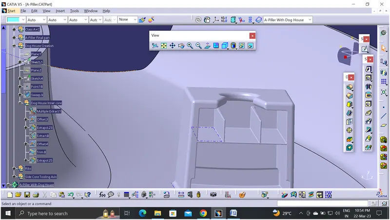
Step 17: Finally using union trim option we trim the Dog House with Ribs into the part body of A-pillar.
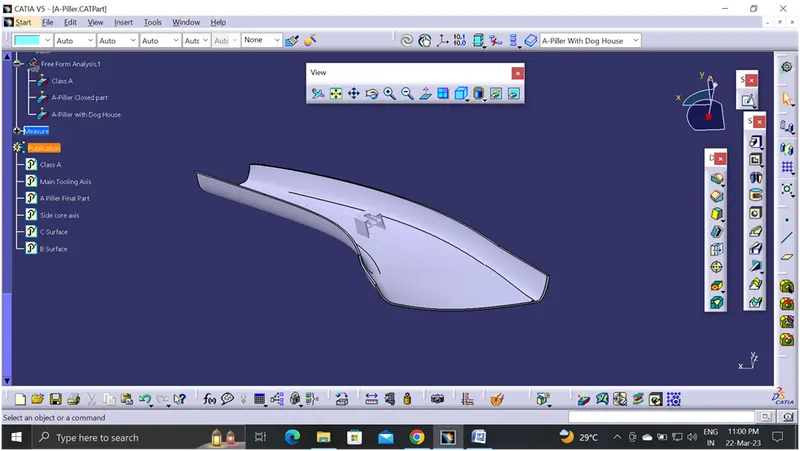
Step 19: Perform draft analysis of the closed body as same above method.
First check with main tooling axis, at 1.5 degree of draft side wall of the dog house not clear the analysis.
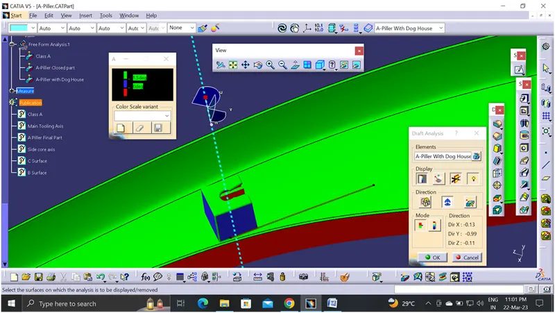
Instead of 1.5 degree, modify the range at an angle of 1.49 degree all the faces clear the draft analysis.
Now perform the draft analysis for side core axis. When we give 0.5 degree of draft some faces are in blue colour
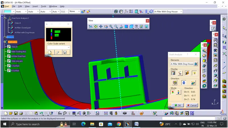
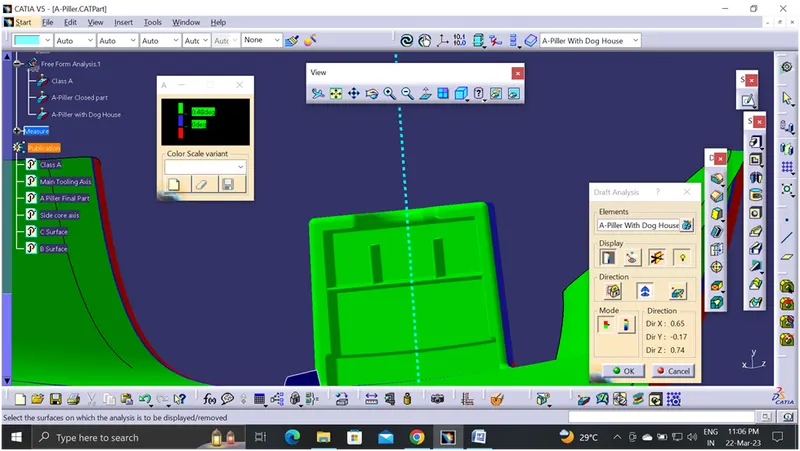
When we changes the angle as 0.48 degree all the inner side of the dog house clear the draft analysis.
Conclusion:
- As per master section A-pillar with dog house part created
- Design the Dog House and Ribs as per the master section guidance.
- Draft analysis performed for each and every aspect and clears.
View Mode: