Week 9 - Project - A pillar Design with Master Section
Aim :
To create the 'A Pillar with engineering feature' from the master section given with the Class A surface. Create the tooling axis and perform the Draft analysis for the final solid part.
STEPS TO BE FOLLOWED :
- Creating the tooling axis.
- Draft analysis of Class A surface.
- Creating Class B surface.
- Creating Class C surface.
- Close Surface and Create solid body.
- Draft analysis of Solid body.
- Engineering features {DOG HOUSE FROM MASTER SECTION} are created.
- Draft analysis of Solid body with engineering features.
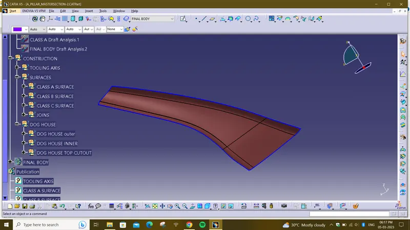
Given Class-A Surface :-
In automotive design, a class A surface is any of a set of free form surfaces of high efficiency and quality. It gives the aesthetic of the component which is created by the styling team and gives to the part design engineer to create the part with all engineering aspects.
CREATING THE TOOLING AXIS :
- Class-A surface is first analyzed to create the tooling axis or tooling direction that molds pull apart in injection molding. Tooling direction is important for plastic product design as it decides the direction for mold separation.
- First check the connectivity of the given Class A surface by using the Boundary or Join feature to visualized and repaired the open edges of the surface.
- And then, analyse visually the best suitable plane or surface for tooling axis.
- First check the connectivity of the given Class A surface by using the Boundary or Join feature to visualized and repaired the open edges of the surface.
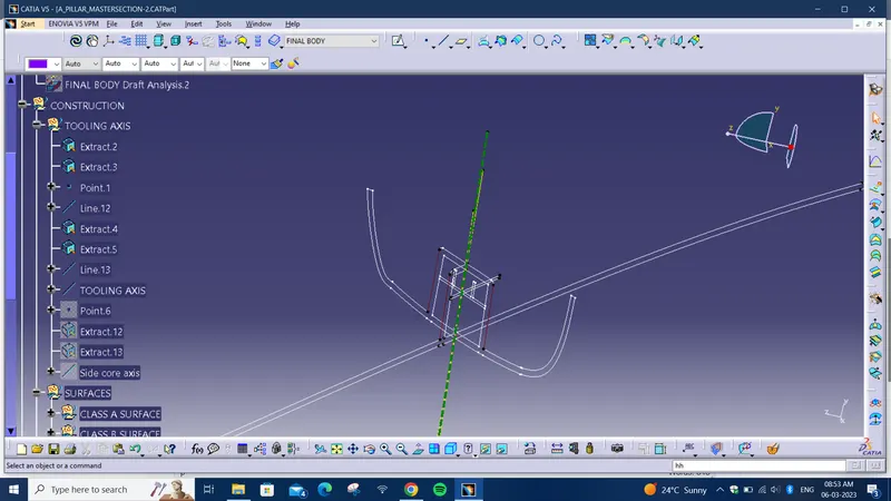
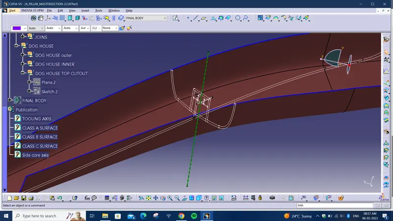
For this part tooling axis creation is done by using the mater section which is given along the Class A surface. Because in this master section the Dog house is there and the Draft for the wall of the Dog is given by the tooling axis. So can take tooling axis from the master section. This master section and Class A surface is given below.
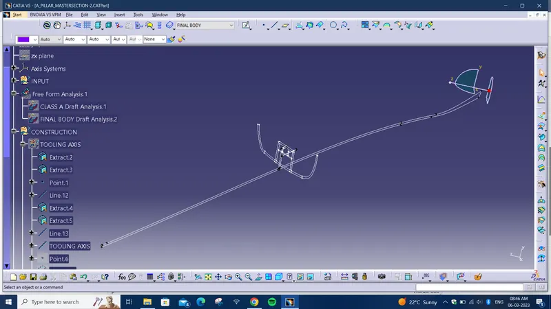
- From the master section first I have extracted 2 lines along width of the master section.
- Using bisecting method I created the line.
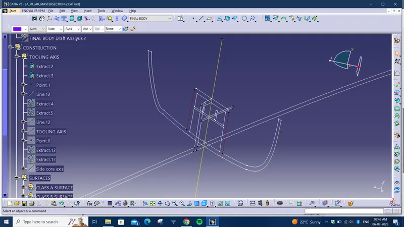
- Next I extracted 2 more linnes from master section along the length direction.
- Using bisecting method I created the line.
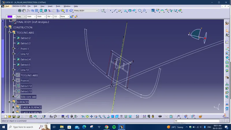
- From the above two lines using the Bisecting method I created the Tooling Axis.
DRAFT ANALYSIS OF CLASS A SURFACE:
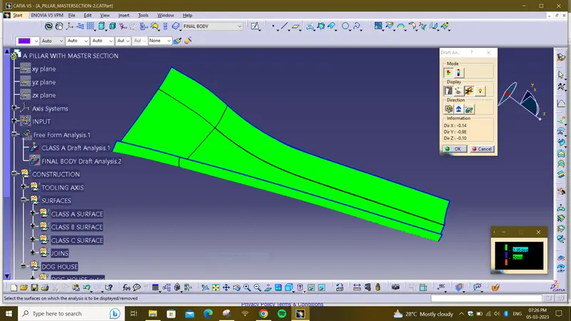
The Draft Analysis command enables you to detect if the part you drafted will be easily removed. This type of analysis is performed based on color ranges identifying zones on the analyzed element where the deviation from the draft direction at any point, corresponds to specified values.
- Before going to drat analysis go to customized view parameter >under mesh >check material and then click ok.
- Now for draft analyses go to insert » analysis » feature draft analysis.
- Use the compasss to define the draft direction.
- In the colour scale change the draft angle to 2.95 degree.
- The component changes to green in indication of passing draft angle.
- Use running point to check the angle on the component.
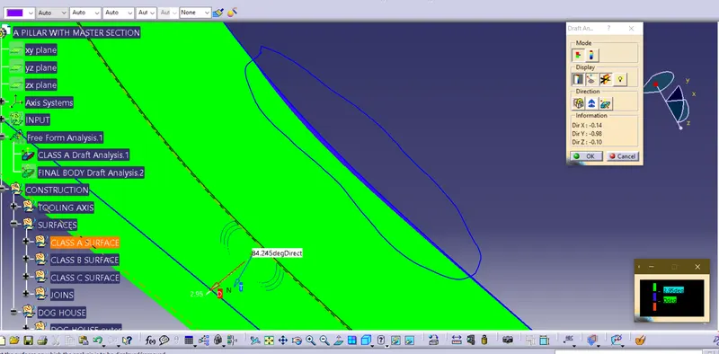
Small porton of the class A surface is not clearing the draft analysis as shown below.
Class B surface :
we offset the Class A surface and get the B surface body here we offset the 2.5mm value so we get the thickness is 2.5mm is mention in above so we offset the A surface for 2.5mm .
After the offset we get the surface but in that offset some patches of surface is missing so we required to solve it.
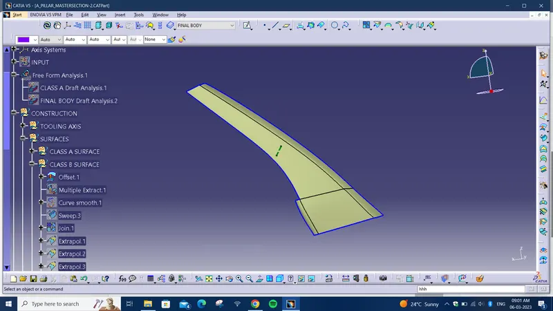
Final Class B surface:
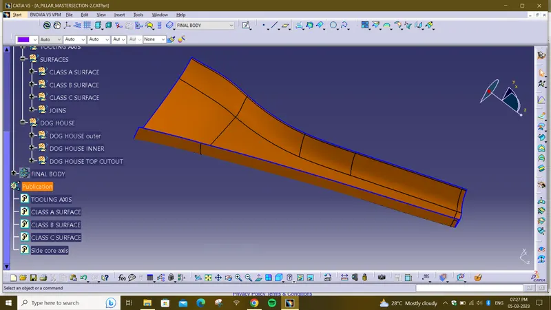
Class C Surface:
To create a Class C surface, first, extract the boundaries of the Class A Surface.
Now using the Sweep option create the surface. To perform this operation, Go to the Toolbar > Sweep > Profile type > Line > Subtype: With draft direction > Guide curve 1- (select the extracted boundaries) the in Draft direction (select the tooling axis) angle and length as 3deg and 87 deg respectively and click ok.
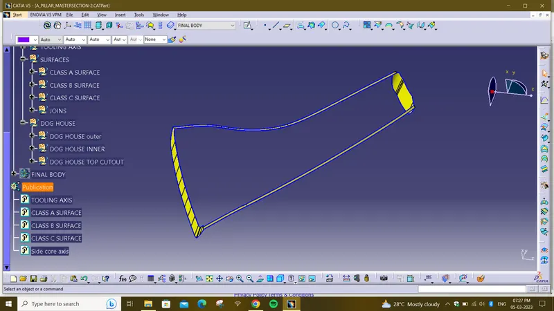
CLOSED SURFACE OR A+B+C SURFACE:
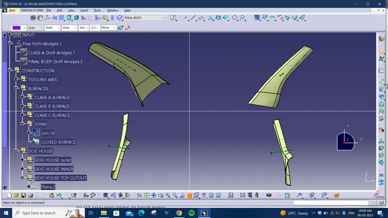
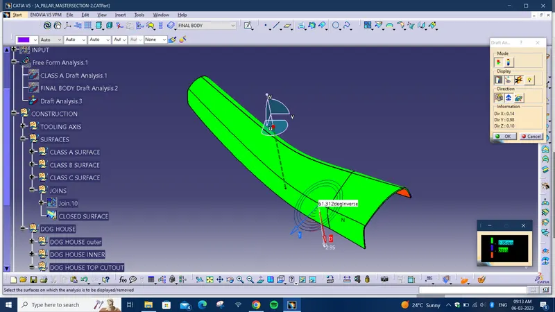
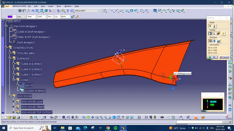
CLOSED SURFACE DRAFT ANALYSIS:
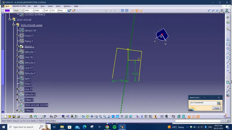
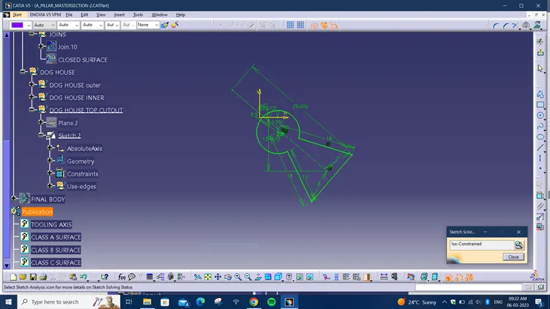
ATTACHMENT FEATURE DOG HOUSE:
SKETCHES REQUIRED:
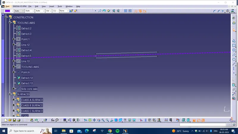
SIDE CORE TOOLING AXIS:
- It is created alonf the mastersection of the dog house.
- Two lines are extracted from master section and using These lines and a point by BISECTING method SIDE CORE TOOLING AXIS is created.
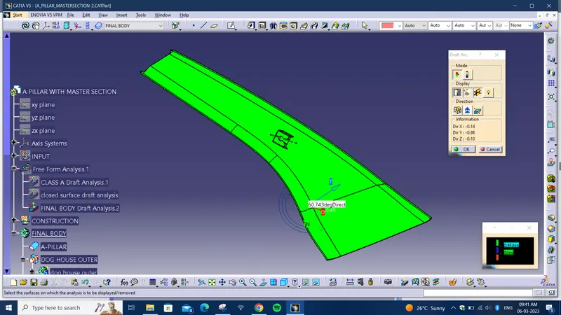
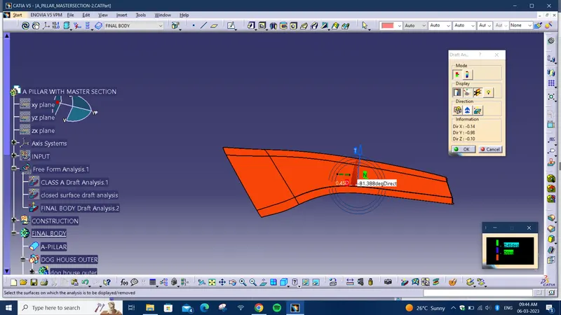
FINAL BODY DRAFT VIEWS with main TOOLING AXIS:
- Draft analysis is cheked with 0.45deg.
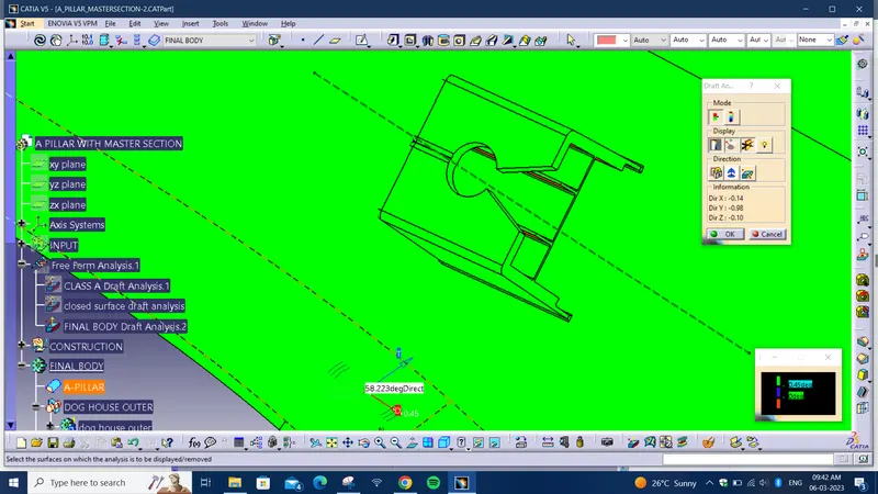
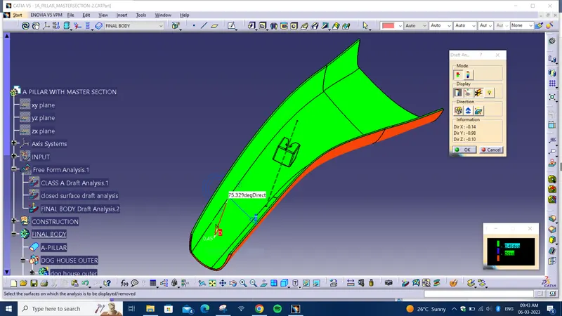
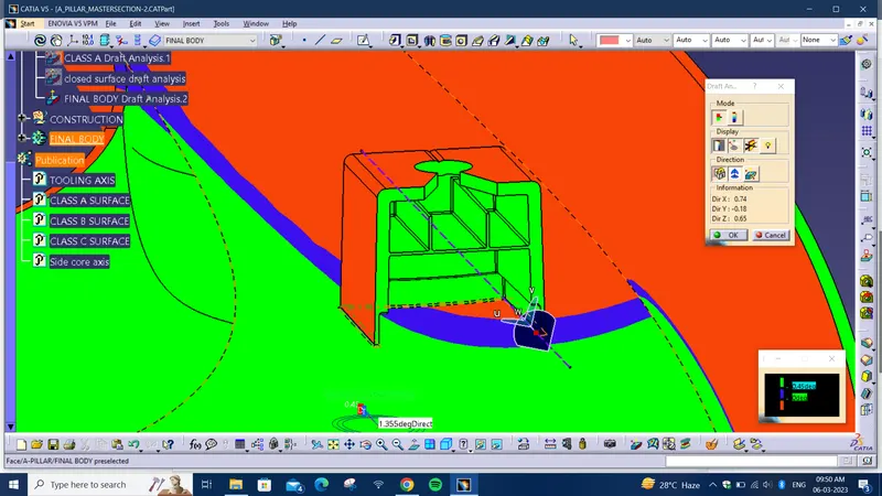
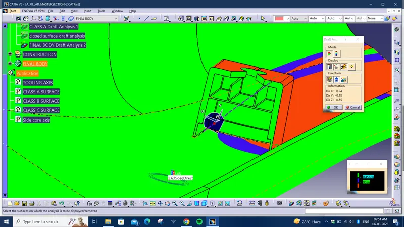
FINAL BODY DRAFT VIEWS with SIDE CORE TOOLING AXIS:
- Draft analysis is cheked with 0.45deg.
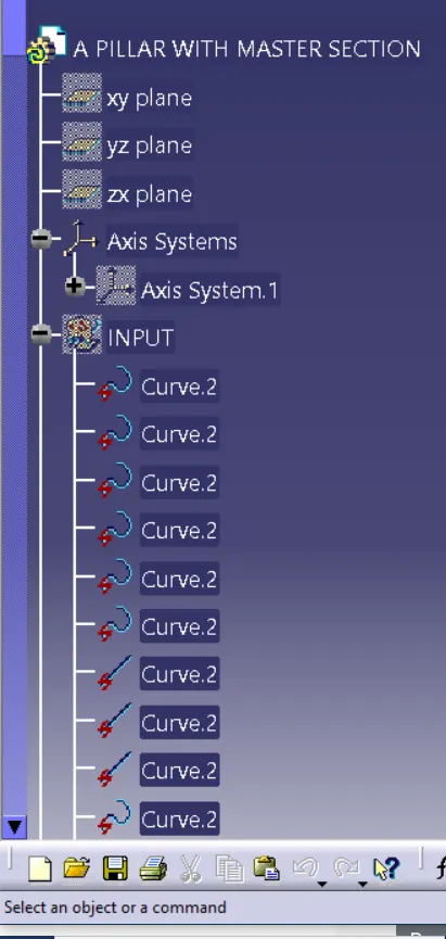
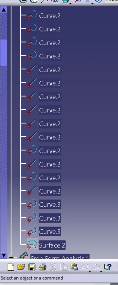
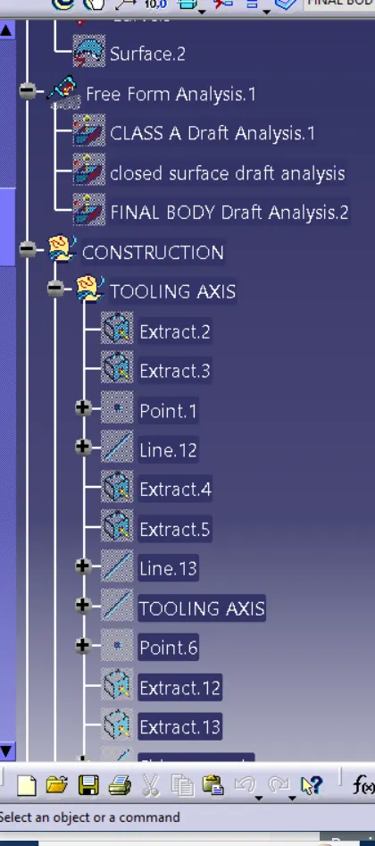
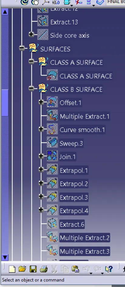
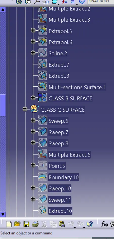
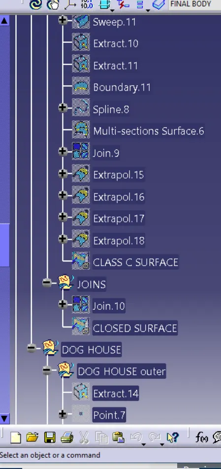
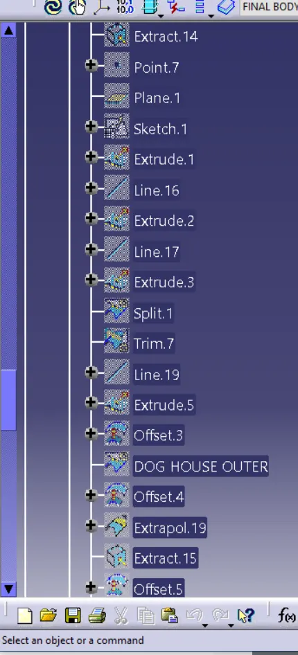
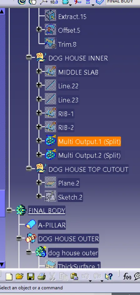
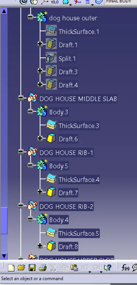
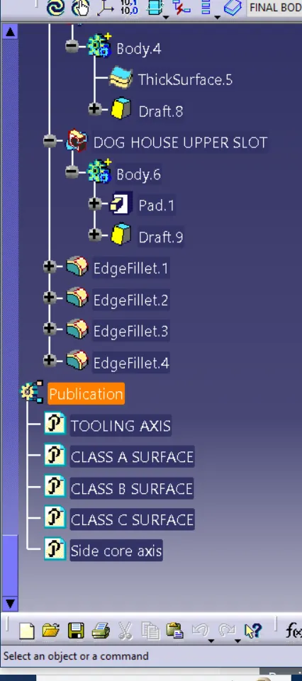
TREE STRUCTURE:
Conclusion :
The A-Pillar with engineering feature is created by considering Master Section and Design Methodology.