Week 9 - Project - A pillar Design with Master Section
The basic procedures for the A-Pillar design are:
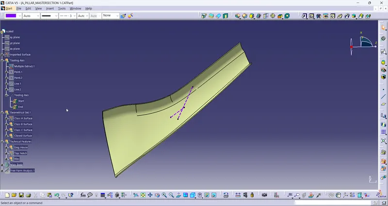
Import the Class A surface and check if there is any patches in the surface. If there are any patches then it should be cleared by using the surface design commands.
The tooling axis is then created by various methods. Here Bisecting Line method is used to create Tooling Axis.
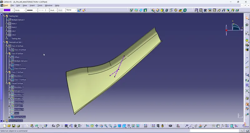
Then the Class B Surface is created. this is created by offsetting the Class A surface to the given thickness (2.5mm) inward to the Class A surface. The patches in the Class B surface is checked. It is then cleared by using surface commands like Sweep, Multi section Solid, join, trim etc. Here the Multiple extract and the sweep command is used to clear the patches in the surface. Once the surface is formed it is then joined with the offset surface and made into a complete Class B surface.
It is then followed by creating the Class C surface. The Boundary of the Class A is extracted and by using the sweep command to the inward direction the Class C surface is created.
The trim the Class C with the Class B and firther it is joined with the Class A surface. Thus the closed surface is formed .
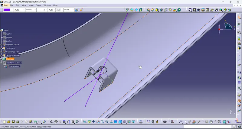
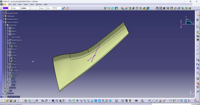
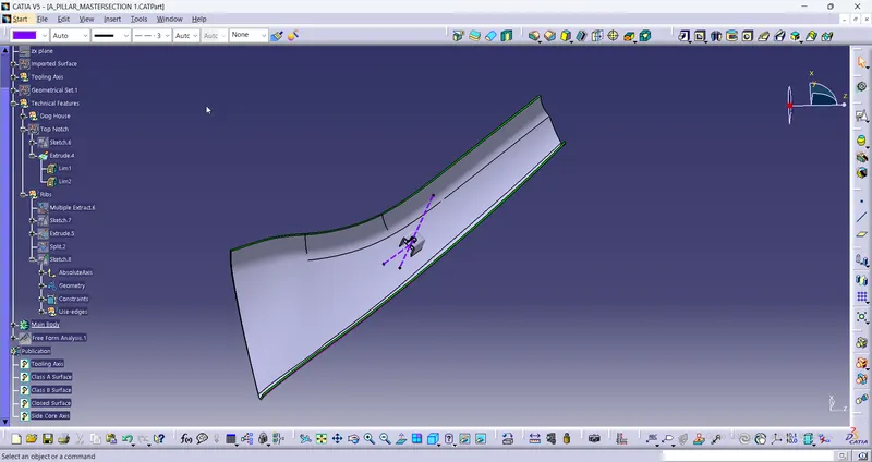
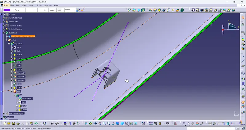
This closed surface is then taken to the Part workbench. By using the Close surface to solid command the solid of the A-Pillar is designed. Now the Dog house and the Ribs in it are formed by using the solid modelling commands with respect to the given dimensions.
These two bodies are created seperately in two different bodies. Then once these bodies are created, first the Ribs are added to the Dog House proceeding with adding to the closed solid from the surface design. Thus the single complete solid is formed.
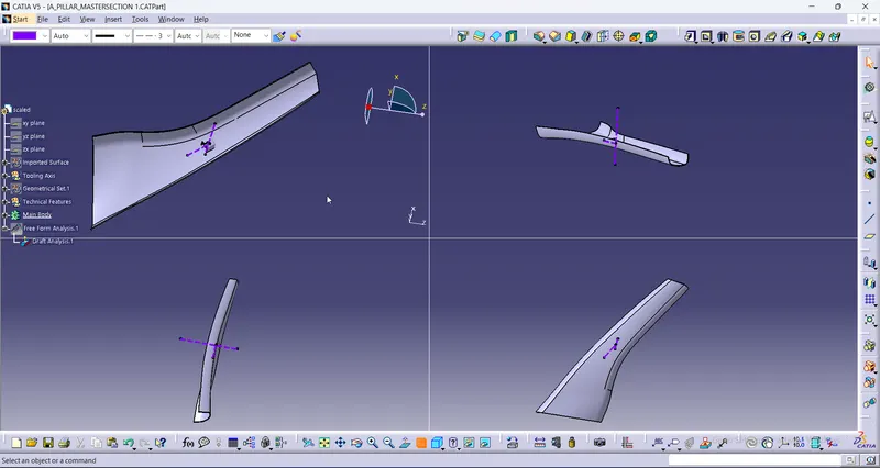
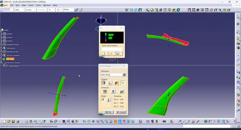
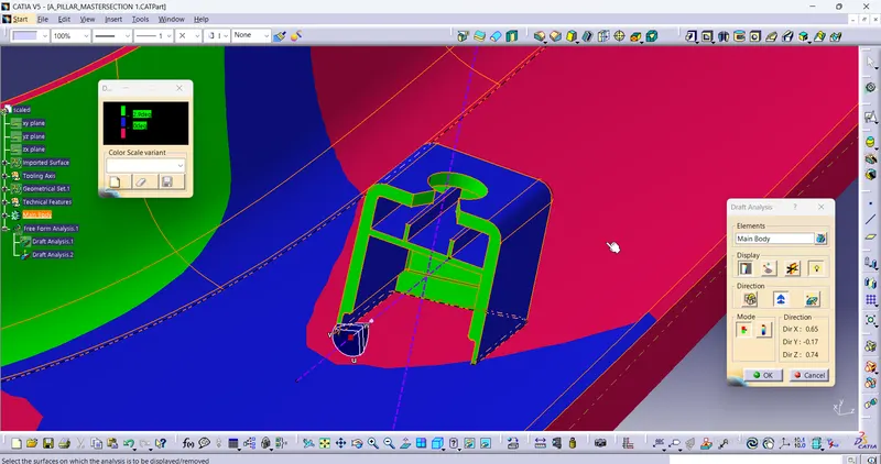
With respect to the Main Tooling Axis, the whole body is subjected to draft analysis for the maximum of 3 degrees. And with respect to the Side core tooling axis, the Dog House along with the ribs are subjected to draft analysis.