Week 8 - Challenge 5 - Door Trim Lower
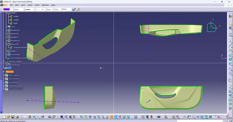
Creation Of Class A Surface
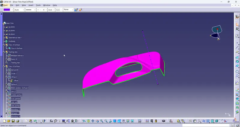
- Class A surface is obtained as the input.
- Join all the surfaces to obtain Class A surface
- Publish class A surface
Creation Of Tooling Axis
- Tooling axis is created by selecting one of the natural axis as it clears the draft.
- Here, tooling axis is created by extracting one of the flat surfaces for creating a point and a new axis is created
- Line is created using line tool at the point and direction normal to the plane is used for creating tooling axis.
- Now publish Tooling axis.
Creation Of Class B Surface
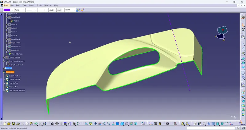
- Class B surface is to be created. Class A Surface is offsetted for 2.5mm.
- By using the extract, extrapolate, join, trim, multiple extract the patches are formed into surfaces. The prime most improtant is Fill command should not be used.
- Fillets are measured from the Class A surfaces and appropriate fillets are provided for Class B surface by subtracting the thickness of the component.
- Publish class B surface.
Creation Of Class C Surface
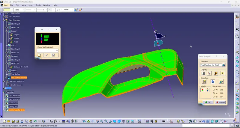
- Now class C surface is created from the boundaries obtained from the Class A surface. This boundary is provided as the input curve for sweep command. Using sweep command - with reference to draft , class C surface is created.
- Appropriate sweep is the provided considering the flash and considering manufacturing procedures. Surfaces are extrapolated if necessary.
- Publish class C surface.
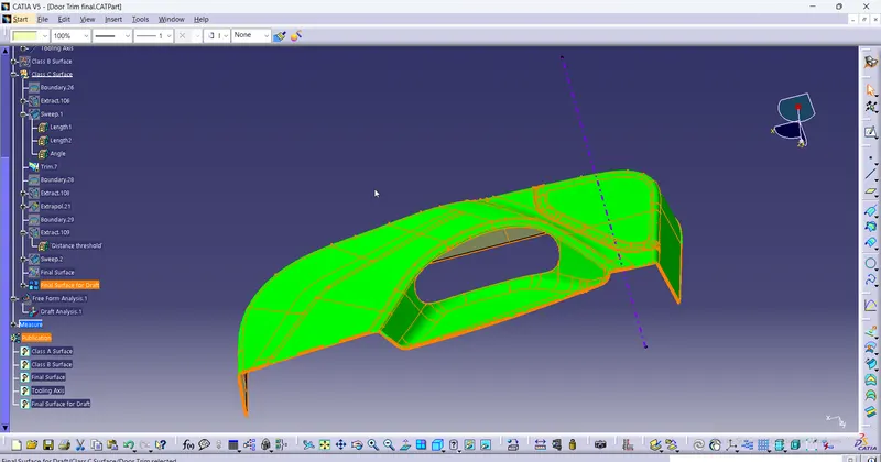
Finally class A, Class B, Class C surfaces are trimmed and joined to form a single closed surface. then the Draft analysis is done in it.