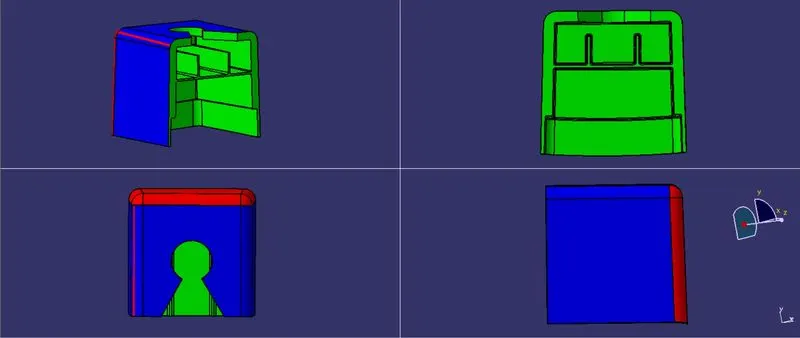
A pillar Design with Master Section
OBJECTIVE
- To design the A PILLAR Plastic component using the given Class-A surface and master section with a thickness (T) of 2.5mm.
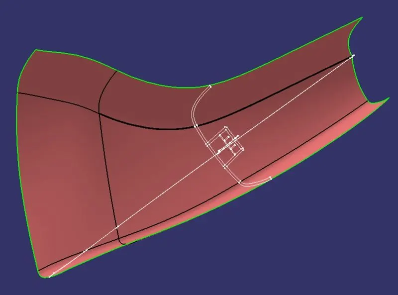
- To create the Dog House considering the master section design and rules mentioned.
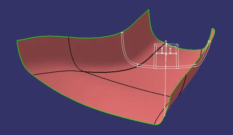
-
Doghouse wall thickness at the intersection of the part wall ( C ) should be 40% or less than the main wall stock ( T ).
-
The height of ( B ) should be between 3.0 – 6.0 mm
PROCEDURE
1. Defining a Tooling axis for the Class-A surface
- Step 1: Check the connectivity of the surface and ensure there is no gap in the class A surface. The boundary command helps by highlighting the boundary of all the edges thus we can visually check for gaps in the class A surface.
- Step 2: We extract the plane surface and create a point in the middle of the surface. we also create lines on the master section of the dog house side walls.
- Step 3: Next we create a bisecting line through the point. This is the main tooling axis.
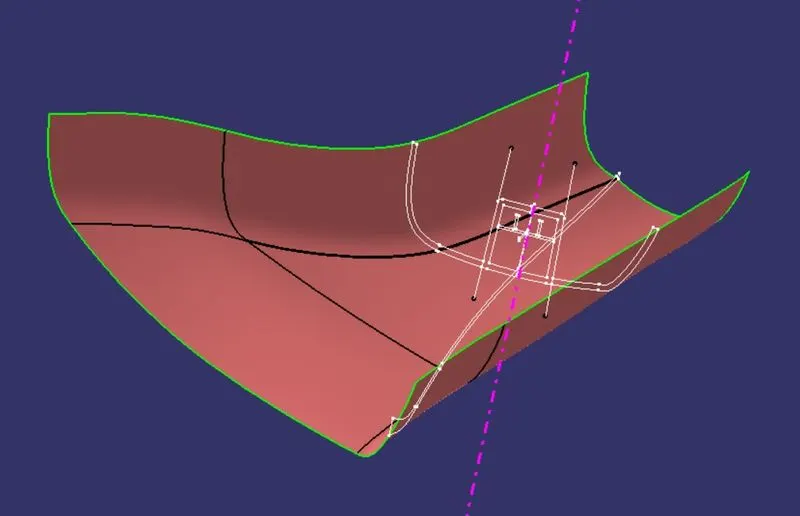
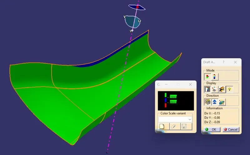
- Step 4: We perform a draft analysis on class A and check the angles of the surface we think will create problems in tooling.
2. Creating Class B surface
- Step 1: We offset the Class A surface to 2.5 mm towards the back of class A.
- Step 2:We observe a discontinuity in the offset surface.
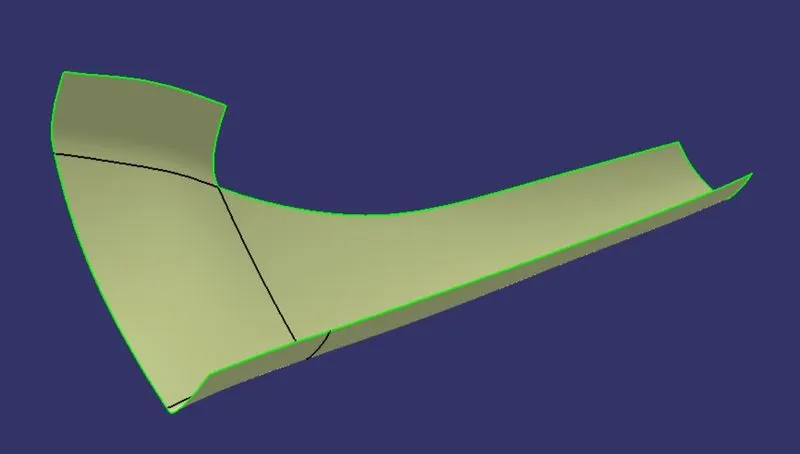
- Step 3: We extract the boundaries and create a sweep with reference surface without giving the surface as the support and the long edge as the guide curve. We join the sweep with the offset surface.
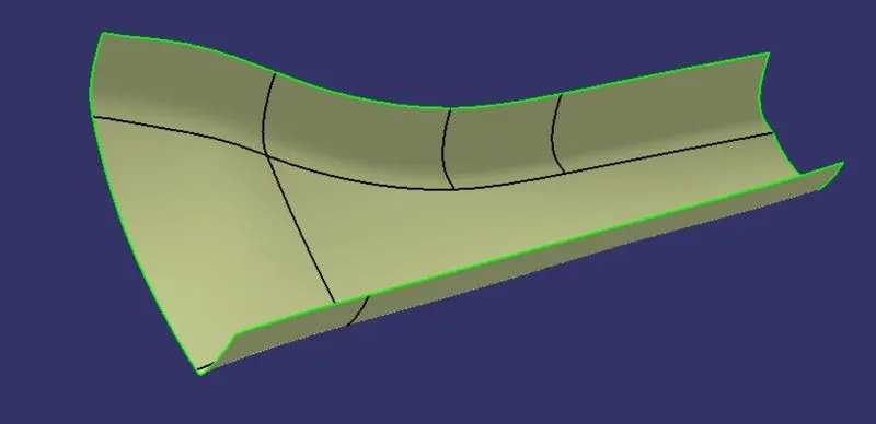
- Step 4: We extrapolate the above surface by a few mm on all the edges to get the final B surface.
3. Creating Class C surface
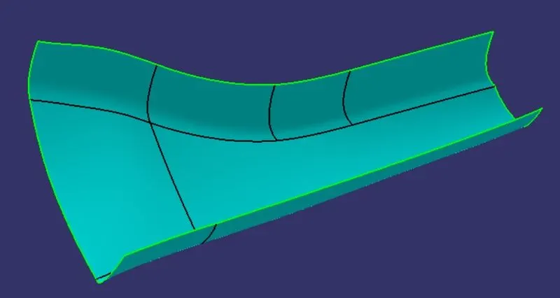
- Step 1: We use the boundary command to extract the side edge boundaries into 4 different boundaries and use sweep with reference surface to create a surface at 90 degrees or 93 degrees where it needs clearing for 6 mm.
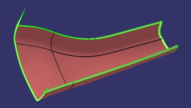
- Step 2: We extrapolate the ends of the above surface and trim all 4 sweeps together to create the final C surface.
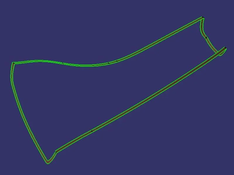
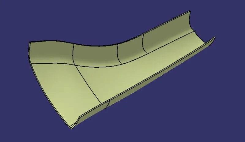
4. Creating the hollow surface part
- Step 1: We use the join operation to join the Class A, and C surfaces and trim them with Class B surface into one body to get the final surface body.
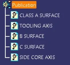
5. Publication of the Tooling axis, Class A, B, and C surfaces
- Step 1: We select the tooling axis, dog house side tooling axis, class A, B, and C surface from the tree and go to Tools->Publication to publish them.
6. Creating the final solid component
- Step 1: We switch to the part design workbench and use the Closesurface feature to create the solid part out of the hollow surface body.
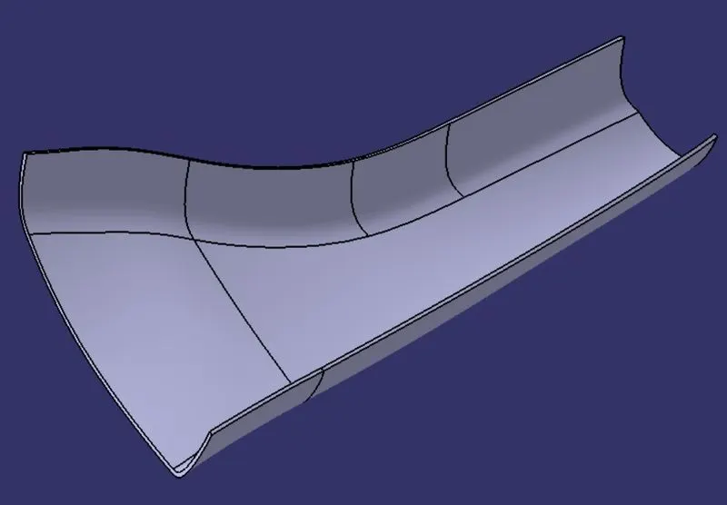
7. Creating the Dog house
- Step 1: We create a plane through 3 different points of the doghouse master section.
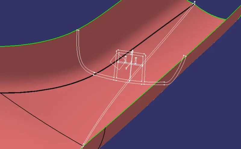
- Step 2: We create a positioned sketch and project the outer edge of the dog house master section and isolate them. we constrain them fully and create the pad for 20 and 10mm.
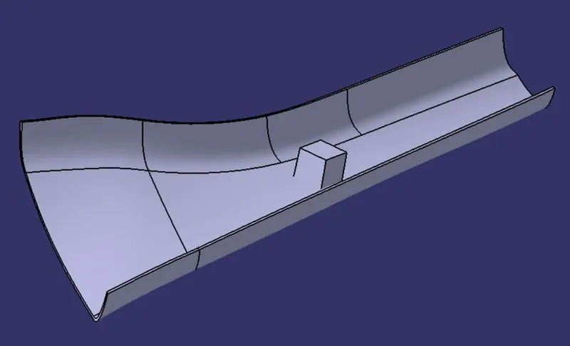
- Step 3: We shell the front and bottom surface for 2.5mm.
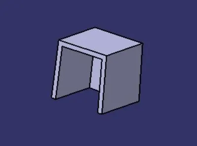
- Step 4: We create a line normal to the above plane. This is the side core axis.
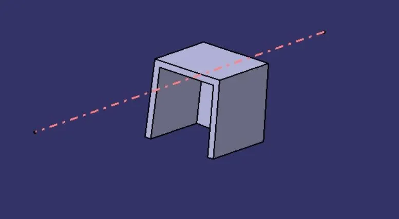
- Step 5: We draft the inside surfaces for 0.5 degrees along the side core axis.
- Step 6: For the coring, we extract the inside surface and offset it for 0.6T (1.5mm). We also offset the base extract for 3-6mm and trim together to get the coring snipping surface.
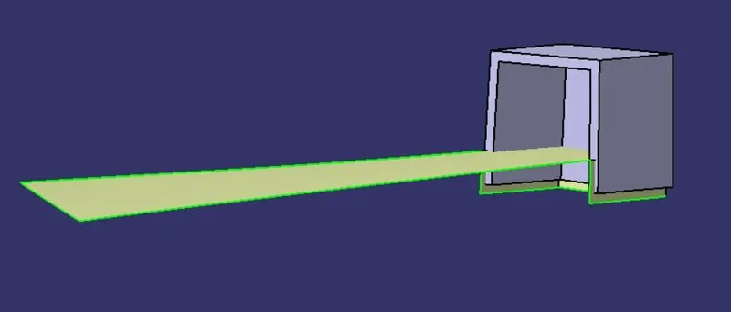
- Step 7: In the part workbench, we snip the doghouse by the above surface to get the coring.
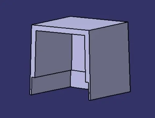
- Step 8: We draft the inside surfaces along the side core axis for 0.5 degrees and edge fillet to get the final dog house canopy.
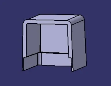
- Step 9: We create another sketch for the locator's ribs. We pad and thicken it with a thickness of 1 mm and create edge fillets and union trim with the dog house canopy.
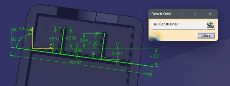
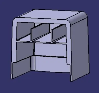
- Step 10: We create another plane at 90 degrees from the previous plane and create a sketch for the cutout.
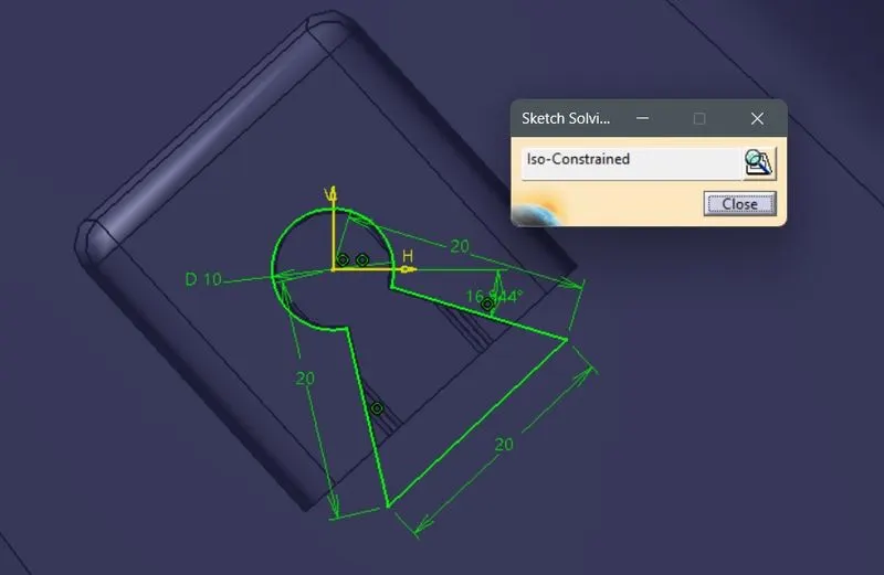
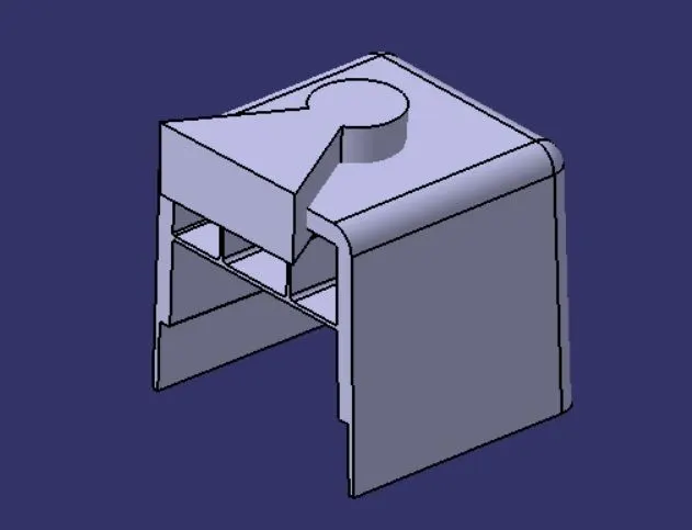
- Step 11: We pad the sketch and remove it from the dog house to get the final dog house.
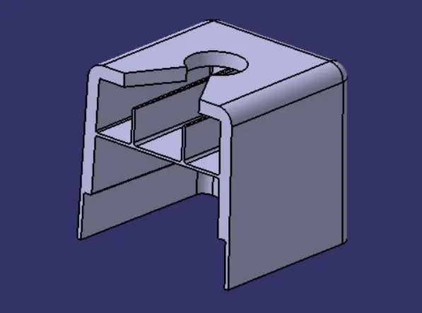
all views
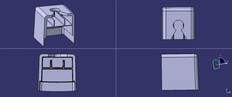
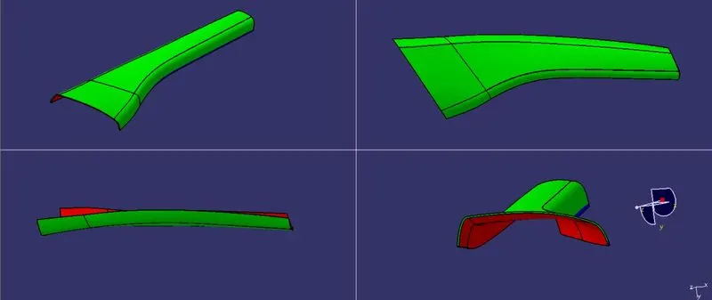
8. Draft analysis
- Step 1: We open the draft analysis command box, select the compass, drag, align it with the tooling axis, and lock it.
- Step 2: We analyze the color scale, input the required draft value and save the analysis.
TREE STRUCTURE
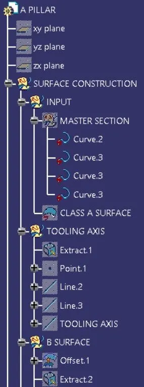
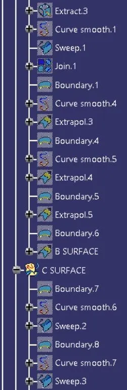
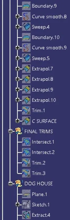
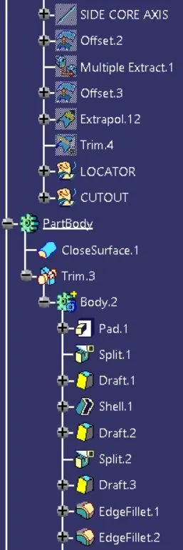
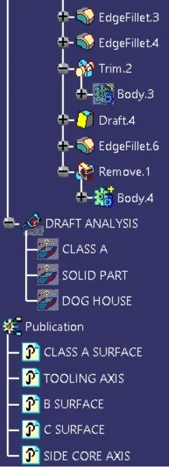
DRAFT ANALYSIS
1. For the final plastic component
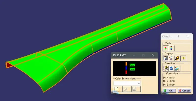
All views
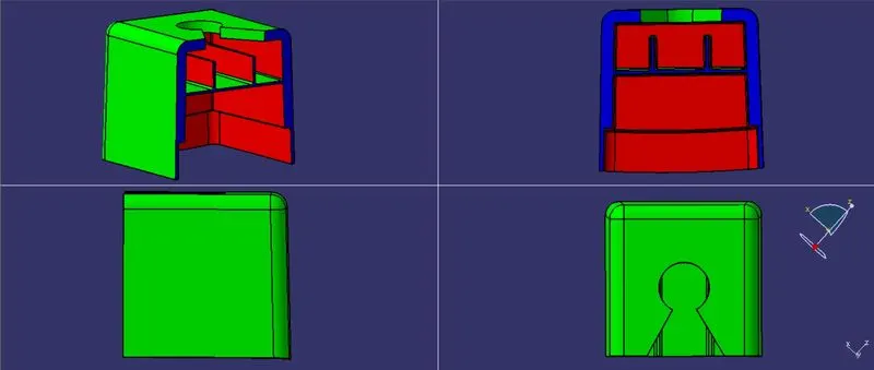
2. For the Dog house along the main tooling axis
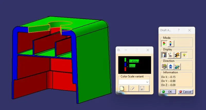
all views
3. For the Dog house along the side core axis
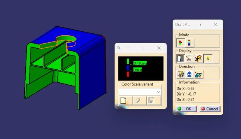
All views