Week 9 - Project - A pillar Design with Master Section
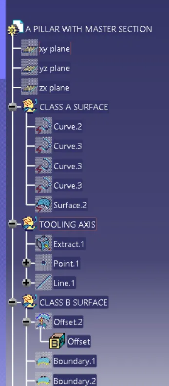
Our first aim to make a closed body.Inorder to this,we have to make Class B Surface and Class C surface out of Class A Surface.
CREATION OF TOOLING AXIS
The first step out of it is making of the Tooling axis
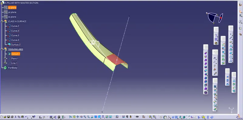
For making the Tooling axis,first we have to find a flat surface and create a point on it.Then create a line withrespect to that point.Thus,the Tooling axis will be formed.
DRAFT ANALYSIS
The next we have to check whether the Tooling axis will clear the draft or not.For that we have to perform the Draft Analysis
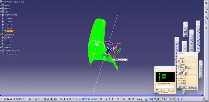
- Go to Insert -> Analysis -> Featured Draft Analysis
- Place the Compass into the Tooling axis
- After inserting the a compass,click anywhere on the surface
- If the green colour occurs,it means that draft is cleared successfully(We can check the angle by enabling the "Analysis under running point"
CREATION OF CLASS B SURFACE
The mentioned thickness given here is 2.5mm.So,we have to offset 2.5mm
After offsetting,some patches will appears
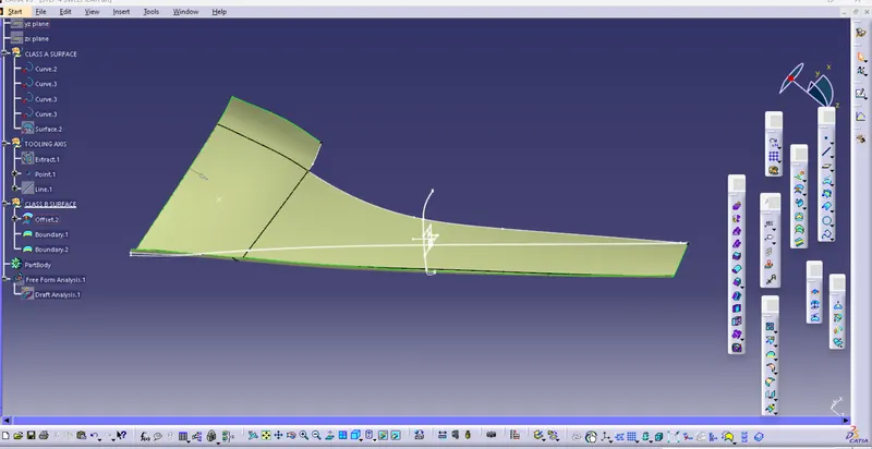
Here only one patch is occured.Here the method applied to clear the patches is application of the Sweep.
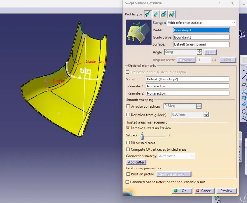
Here the Sweep with the subtype of refernce surface is selected and given the Profile and the Boundary.So,the patches will be cleared.
CREATION OF THE C SURFACE
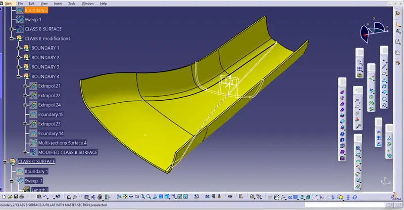
Next we have to perform the Sweep to form the Class C Surface.Here we are using the Sweep with the Reference surface.Do this operation for the all four boundaries.
After performing the sweep join the c surface with the A surface.Then trim the Class A+C Surface with the Class B Surface.Now the Solid body will be formed.
MASTER SECTION
Master sections development takes place during feasibility check and concept validation stages of product lifecycle.These are typically the guides for design requirements and which decides the components packaging after the development of concept design.
Mastersections helps us to decide the feasibility of the concept design,clearences,the packaging and the fixation strategy of a component before converting the concept design into solid 3D engineering design
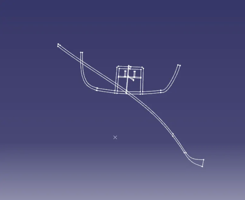
These are the some details about the Mastersection.So,we have to create the solidbody from the Mastersection layouts.Firstly,we are creating a plane parallel to the Mastersection layout by "Plane through three points".Measure the dimensions from the Mastersection and give the values in Pad command accordingely.
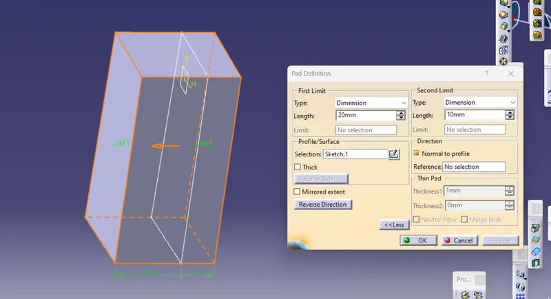
After that,apply the Shell option.The thickness for the shell is 2.5mm.We dont have to draft the outerdirections,because in the Mastersection layout itself it is already drafted.
Next we have to create the inner side core.So,while creating the inner side core,we are not able to create it in the part workbench.We have to do in the Surface itself.
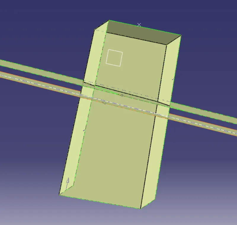
To draw the side core axis :
- Draw a line parallel to the x axis from the intersection point of Solid body and the Dog house.
- Extrude the line
- Offset the extrude upto 4mm upwards (The height of the side core is 4mm)
- Take the multiple extract of the inner surfaces
- Offset the multiple extract upto 1mm in innerside (The wall thickness of side core will be subtracted 1mm from each side)
- Hide the innersurface (Multiple extract region)
- Hide the extrude of the line,only unhide the offsetted surface
- Make trim between the offsetted surface of line extrude and multipe extract
- Perform the split between the surface and the part body
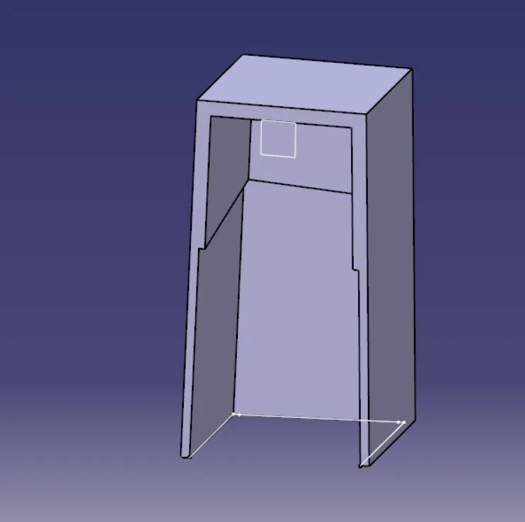
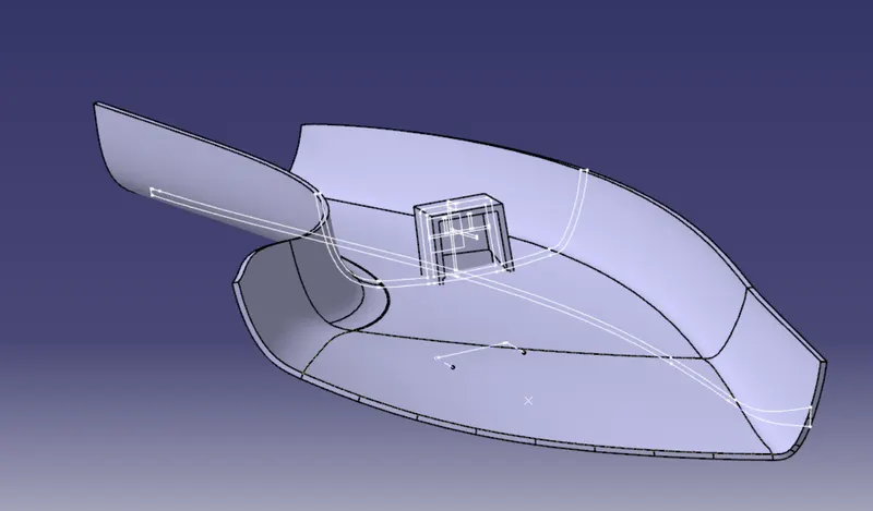
The next step is we have to apply the draft for the sidecore axis.
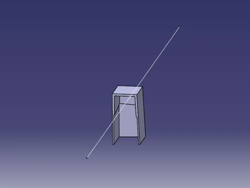
For that we have to make the side core axis which is normal to surface
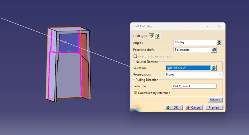
Give the 0.5 degree draft,select the inner elements,give the pulling direction as sidecore axis
The final surface is:
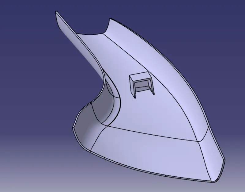
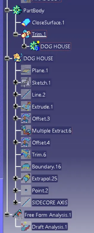
The tree structure