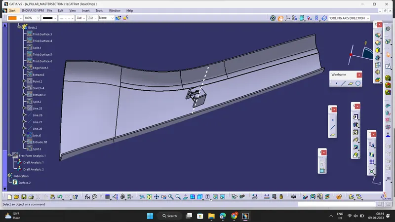
Week 9 - Project - A pillar Design with Master Section
AIM : To understand the given master section and to create a solid body and B-side features or Attachment features for a given class A surface by considering all the design parameters.
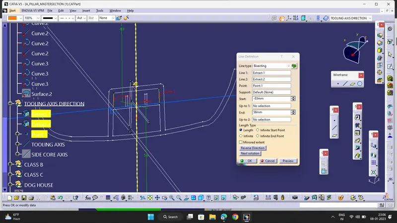
TOOLING AXIS CREATION USING BISECTING METHOD:
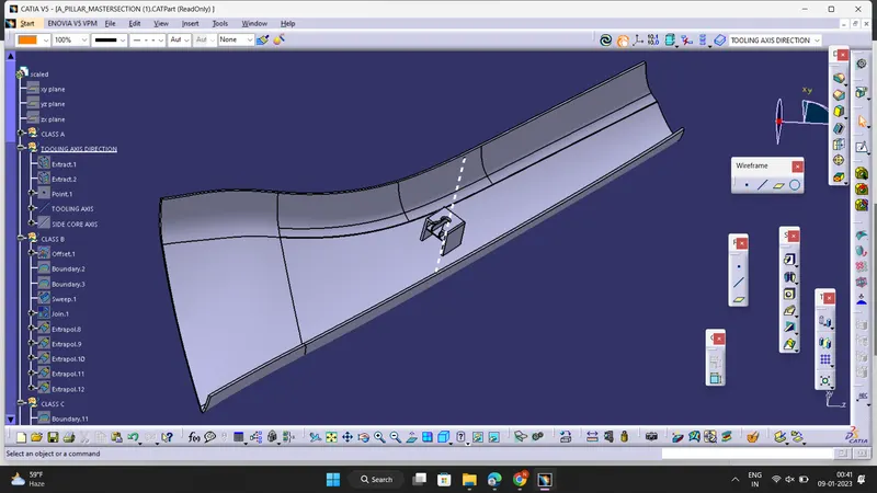
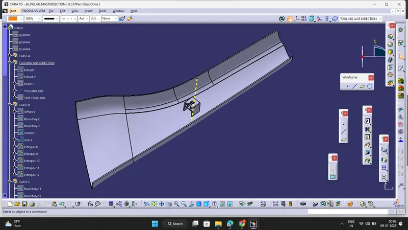
Initially, I created two lines on the master section by using ''point to point line'' and then I created a bisecting line at the centre of those two lines by using bisecting line option in the line command. This is the bisecting line method to create the required tooling axis .
DRAFT ANALYSIS REPORT :
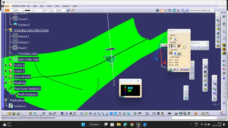
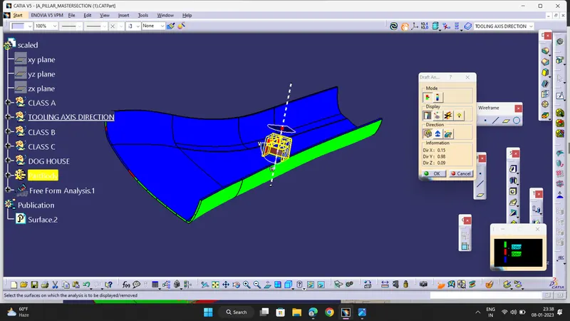
- Follow the steps : Go to insert> analysis> feature draft analysis
- Place the compass on the Tooling axis that is created using bisecting method .
- Select the lock symbol to fix compass along with tooling axis .
- Click on the surface then various Color codes will be appeared and Draft angle is applied . Make sure that the surface is within the permissible limit of the draft values. The surface should be green and nominal draft value should be 3deg .
- Thus the draft analysis on the class-A surface is successfully performed.
FOR SOLID BODY :
CLASS B SURFACE CREATION :
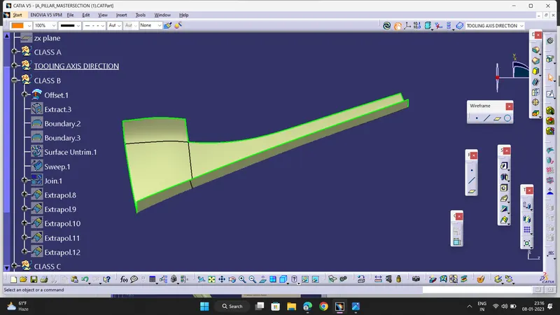
To create the class B surface initially, I measured the thickness of the master section which is 2.5mm . So I offset the class A surface to 2.5mm to the inside direction. But the fillets create the errors in class B surface i.e the styling fillets on the class A surface are not offset properly, it created the patch on the offset surface. To overcome that I used the sweep command to close the patch on the offset surface .
INITIAL OFFSET PATCH :
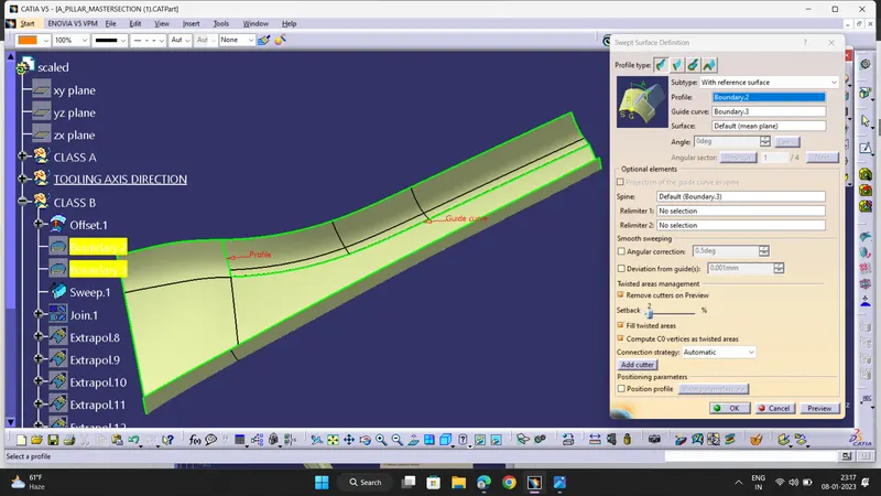
Now I extracted those left patches and used them as guide curves while using Sweep Command in order to fill the patch of class B surface as shown
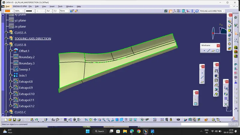
FINAL CLASS B SURFACE :
CLASS C SURFACE :
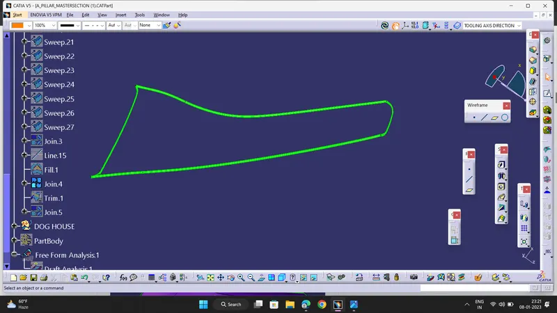
In order to create the class C surface we follow A + C - B Rule . So I used the sweep command to the class A surface edges a by taking reference surface as CLASS A for 4mm inside with 90deg. After the creation of the class C surface, the surface edges are needed to be extrapolated to intersect properly from all 4 sides. I trim the surfaces which extrapolated, to get the closed class C surface. I joined the class A surface and Class C surface to get a single surface of class A+C surfaces. I trim the Class B surface with class A+C surface join, to get the closed surface to create the solid body.
FINAL CLASS C SURFACE :
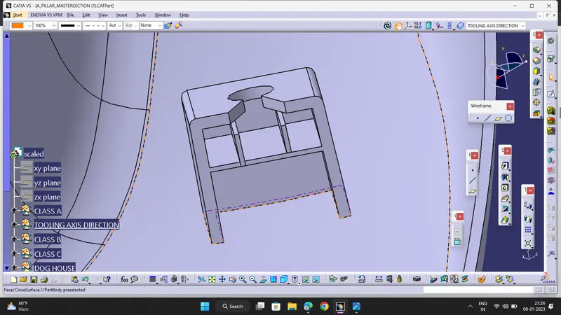
DOGHOUSE CREATION :
Follow the steps
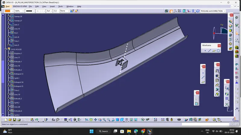
- To create the dog house on the B-side, I extracted the lines on the master section and I create a plane to extract the lines concerning the master section.
- I extracted the faces which are required to create the shell for the dog house, and I trim the surfaces with each other as per the master section dimensions.
- I created the side core access, by creating a line at the centre of the back surface by creating the point.
- I thicken the shell for mm to inside. After thickening the surface, I gave deg draft to inner surfaces of the dog house.
- Now we need to give the bottom cutout for the dog house. To give the bottom cutout, I extracted the surface and offset it to 1mm outside (the bottom cutout should be 40% of the thickness of the dog house). I extract the upper surface of the dog house and offset it to 17mm bottom direction, to trim with the offset of the inner surface.
- After trimming the bottom cutout surface, I split the surface from the solid shell of the dog house. I gave a 0.5deg draft angle to the bottom area concerning to the side core axis.
- I created the rib base and ribs concerning the master section dimensions, and I gave a 0.5deg draft angle to the rib base and ribs. After drafting the rib base, I added the rib base and ribs to the dog house shell to make a single body.
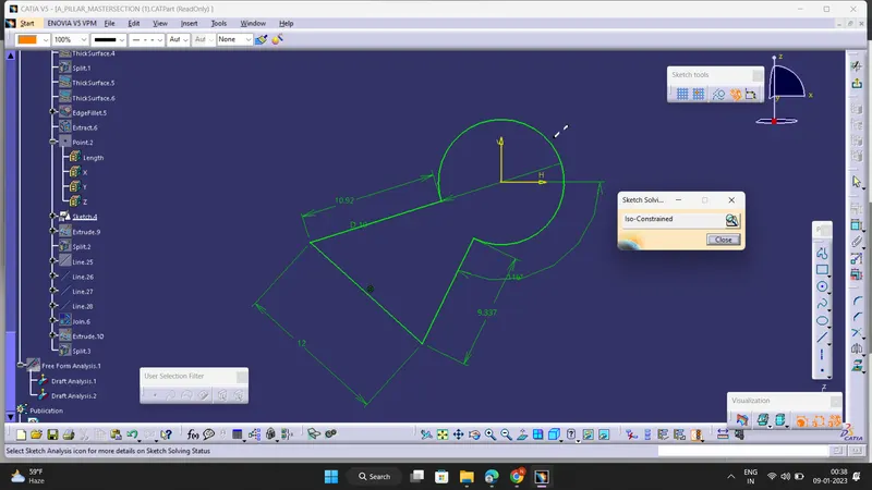
- I created a sketch for the top cutout on the dog house, and I pad the sketch to the downside and removed it from the dog house part body.
- icture of the sketches with Sketch solving status’s geometry tab :
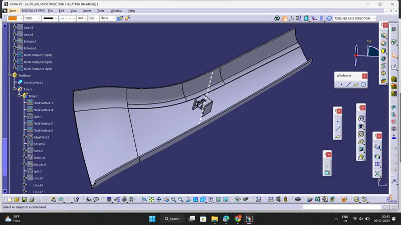
TREE STRUCTURE :