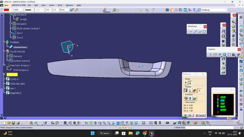
Week 8 - Challenge 2 - Switch Bezel Design
AIM : To Create the Switch Bezel Plastic component through the given Class-A surface .
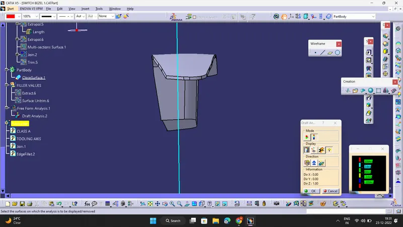
REPORT ON DRAFT ANALYSIS AND TOOLING AXIS CREATION :
1)DRAFT ANALYSIS :
- Follow steps : Go to insert> analysis> feature draft analysis
- Place the compass on the Tooling axis that is created using bisecting method.
- Click on the surface and see that the surface is within the permissible limit of the draft values.
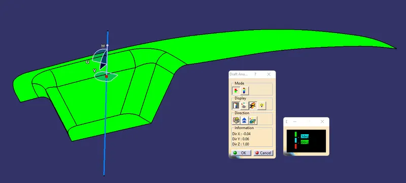
- The surface should be green and nominal draft value should be 3deg .
- Thus the draft analysis on the class-A surface is successfully performed.
2)TOOLING AXIS CREATION BASED ON BISECTING METHOD :
First ,the base surface of the class A surface was extracted and a point at the centre is created and then an axis system was inserted to the point .
Then, using project intersection along yz plane is created first and the two inclined lines were drawn inside the positioned sketch.
Then bisecting lines with the two inclined lines were drawn.
Now the same procedure is repeated along the xz plane next but on one side we don’t have inclined lines so the centre point is used to extrude a line along the z-direction and gave a measurement of 3 degrees .
With these two lines from sketches 1 and 2, the bisecting line is created . This will be the correct tooling axis for the component .
- Screenshots of the Draft analysis report for both the given Class-A surface and the final plastic component
CLASS A SURFACE :
FINAL PLASTIC COMPONENT :
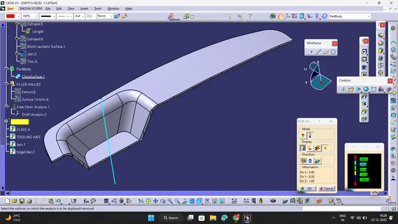
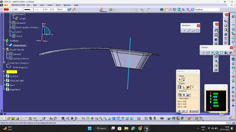
- Screenshots of the solid model with the proper color code of the draft angle in various orientations (Isometric, Front, Side, and Top View) :
ISOMETRIC VIEW :
FRONT VIEW :
LEFT VIEW :
TOP VIEW :