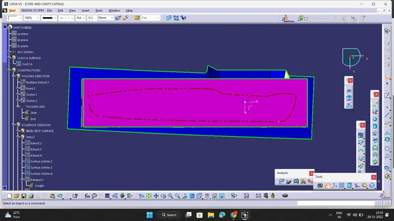
Week 8 - Challenge 6 - Core & Cavity Design
AIM : To Create the Core and cavity blocks for the switch bezel design .
- A detailed report should be done explaining the draft analysis and the tooling axis creation :
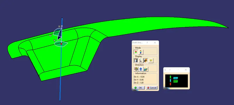
1)DRAFT ANALYSIS :
- Follow steps : Go to insert> analysis> feature draft analysis
- Place the compass on the Tooling axis that is created using bisecting method.
- Click on the surface and see that the surface is within the permissible limit of the draft values.
- The surface should be green and nominal draft value should be 3deg .
- Thus the draft analysis on the class-A surface is successfully performed.
2) CREATION OF TOOLING AXIS DIRECTION USING BISECTING METHOD :
- First ,the base surface of the class A surface was extracted and a point at the centre is created and then an axis system was inserted to the point .
- Then, using project intersection along yz plane is created first and the two inclined lines were drawn inside the positioned sketch.
- Then bisecting lines with the two inclined lines were drawn.
- Now the same procedure is repeated along the xz plane next but on one side we don’t have inclined lines so the centre point is used to extrude a line along the z-direction and gave a measurement of 3 degrees .
- With these two lines from sketches 1 and 2, the bisecting line is created . This will be the correct tooling axis for the component .
- Screenshots of the Draft analysis report for the switch bezel plastic component :
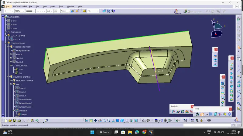
- CORE BLOCK :
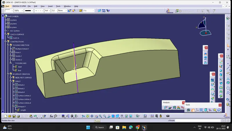
- CAVITY BLOCK :
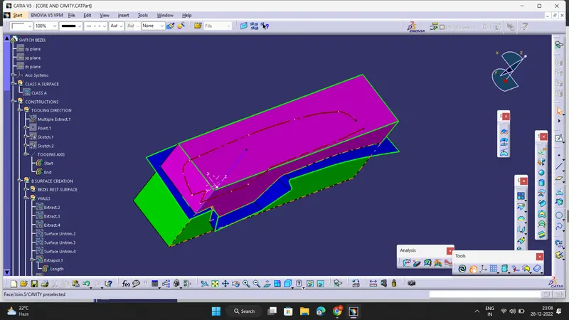
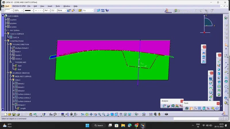
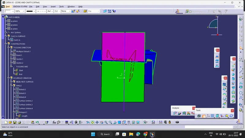
- Screenshots of the core and cavity blocks in various orientations (Isometric, Front, Side, and Top View) :
ISOMETRIC VIEW :
FRONT VIEW :
SIDE VIEW :
TOP VIEW :