Week 9 - Project - A pillar Design with Master Section
DOWNLOAD THE GIVEN CAD MODEL OF A PILLAR MASTER SECTION
- CLASS A SURFACE
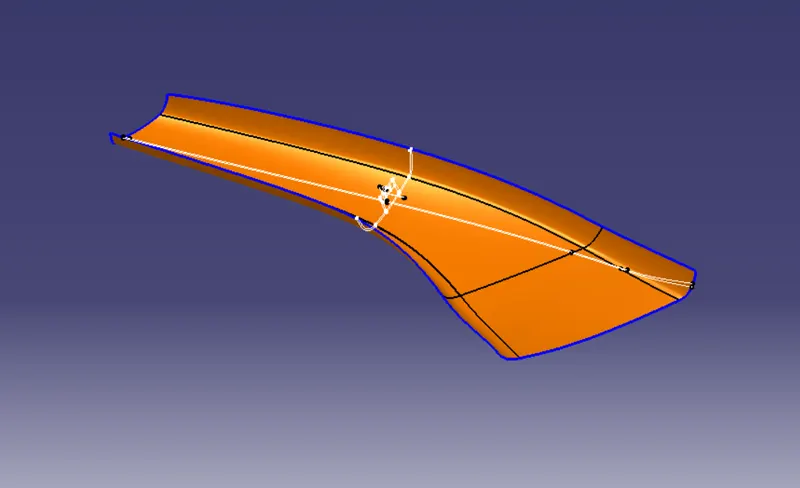
We are aware that Class A surfacing is more art than engineering. The styling procedure has been given digital life.
Prior to observing the Class A Surface closely, as illustrated in the figure below, we must thicken the Class A Surface in accordance with the work at hand.
CREATION OF TOOLING AXIS
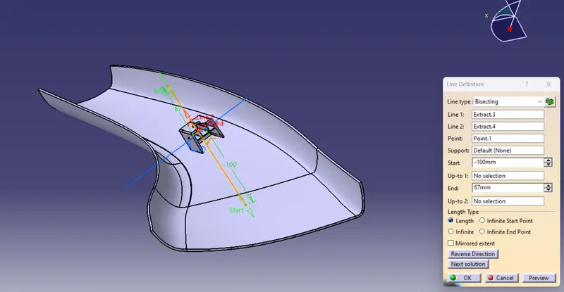
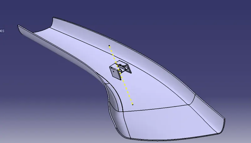
In practice, we require a center of the surface, also known as a tooling axis, depending on the removal of metal from the core and cavity.
- EXTRACT THE LINE FROM THE MASTER SECTION AND THEN USE A BISECTING LINE TO CREATE THE TOOLING AXIS.
CREATION OF CLASS B SURFACE
- Simply offset the given Class A surface using the offset command by 2.5mm.
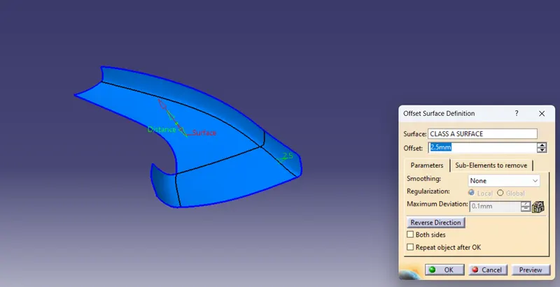
- As you see above figure we have one big gap created due to offsetting the Class A surface. So by using the sweep command we can fill this gap.
- Give Swept, Extract & Extrapolate commands to the Offset Of the Class A surface we got the B Surface as shown in the figure below.
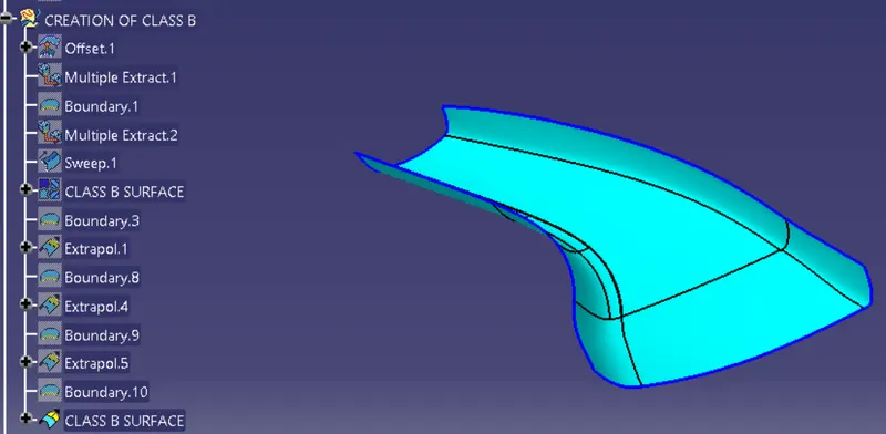
CREATION OF CLASS C SURFACE
- Class C finishes tolerating more flaws than Class A or B finishes. Class C is frequently specified for interior surfaces that are difficult to see or that, when assembled, will be hidden by another part.
- The Class A Boundaries must be taken, swept, trimmed, and joined in order to create the C Surface, as indicated in the image below.
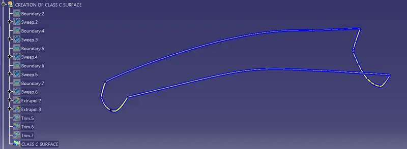
FINAL JOIN AND TRIM
Join the Class A & B Surfaces & then trim with Class C then we Got the Final component as shown in the figure below.
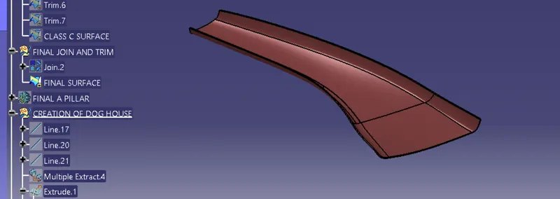
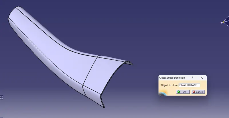
CLOSED SURFACE THE FINAL SURFACE
A volume of space enclosed in all directions is contained by a closed surface.To build the close surface solid body as shown in the image below, go to the part design workbench, click the close surface command, and then click the final trim surface component.
CREATION OF DOG HOUSE USING MASTER SECTION
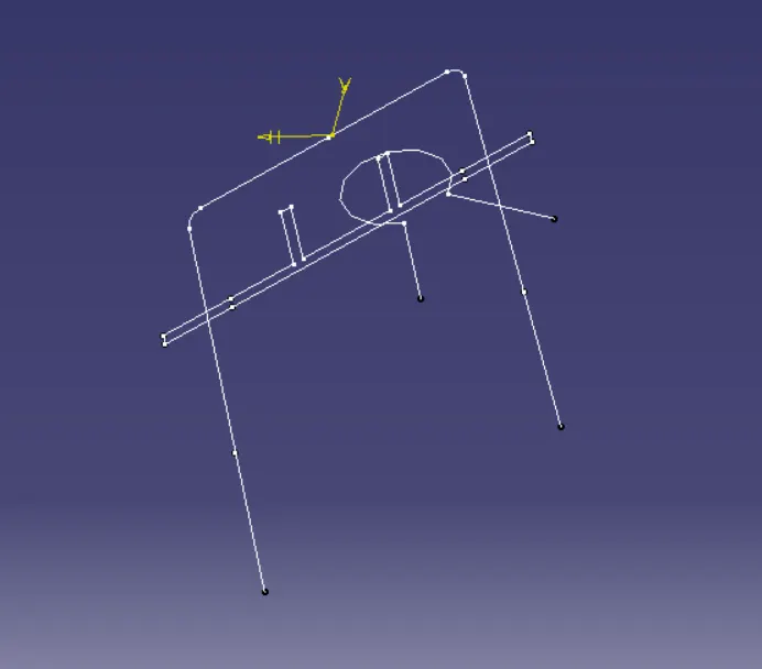
CREATING DOG HOUSE SKETCH
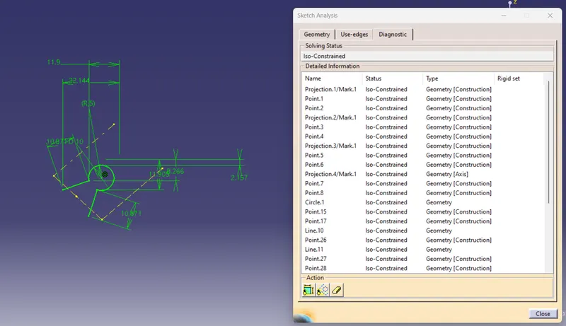
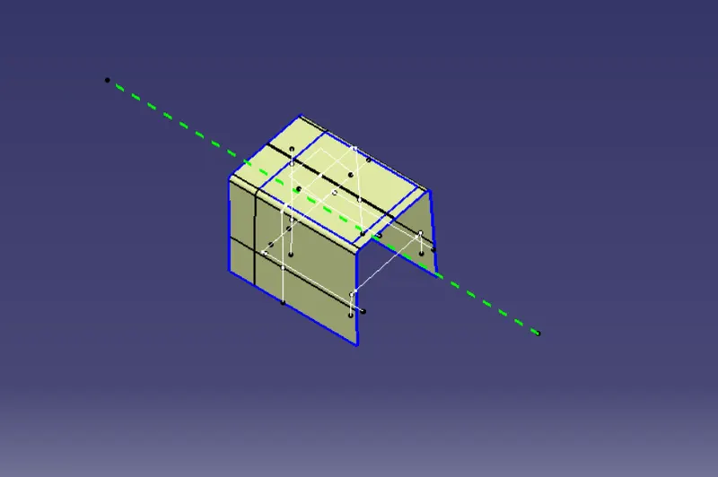
Creation of Side Core Axis
As shown in the figure below, take the axis on the core side with reference to the dog house upper surface.
CREATING LOWER RIB
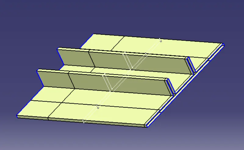
FOLLOWING THE DESIGN CONSIDERATION OF THE DOG HOUSE AND LOWER RIB
- The draft angle should be less than 0.5 degree for inside surface of dog house and 1.5 degree for the outside surface.
- The edge fillet angle should be 0.5 degree.
- edge fillet for the ribs is 0.25 degree.
- dimension is according the master section
FINAL DOG HOUSE WITH LOWER RIB ON FINAL SURFACE
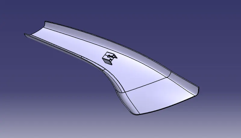
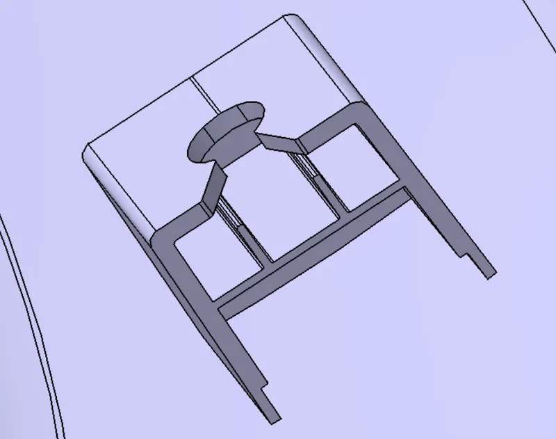
DRAFT ANALYSIS
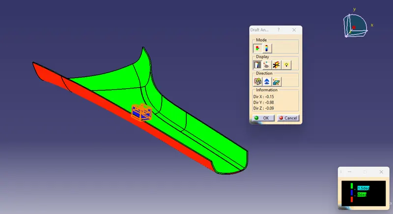
So let's talk about the preliminary DRAFT analysis.
The Draft Analysis makes it simple for the user to check a part for the correct draft angle. The degree of taper for cast or molded pieces that runs perpendicular to the parting line is referred to as a draught angle.
In the draft analysis, there are two modes: Quick and Full, respectively.
The Color Scale, Analysis under the running point, No Highlight representation, and Light effect are concealed when the Display option is selected.
Lock or unlock the direction, Compass & Invert are available under the Direction option.
Therefore, 1 to 3 degrees of angle should be generally appropriate for practical usage. By taking these options into account, we must test our given and final components' draught analysis.
DRAFT ANALYSIS OF CLASS A SURFACE
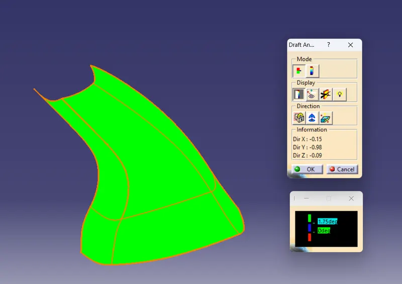
DRAFT ANALYSIS OF FINAL COMPONENT
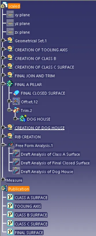
TREE STRUCTURE