Week 9 - Project - A pillar Design with Master Section
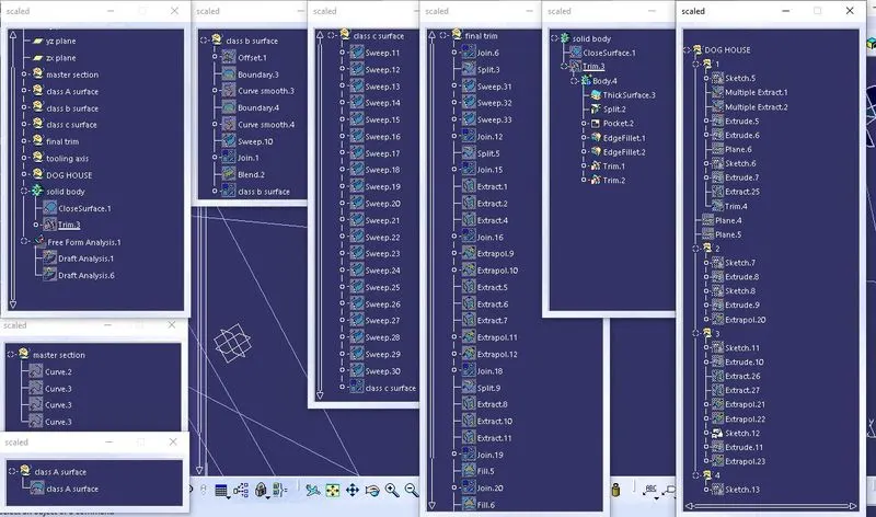
Master section:-
Master sections are the guides for design requirements which decide the component packaging after technical (Styling, Concept or Class-A) surfaces.
Here in this project Master section and Class A surfaces are the input to create the final Cad model with the engineering features.
TOOLING AXIS:-
tooling axis is important and main requirement for an moulding component.It is the way of separation of the mould to mold out the component.
Tooling axis is created by the bisecting method in the given Master section.
CLASS A SURFACE:
Class A surface is the aesthetic look for an component.
So,we should avoid engineering features on the side of A surface.
Here A surface is given as input with Master section.
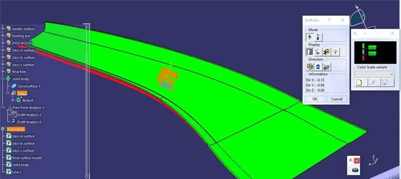
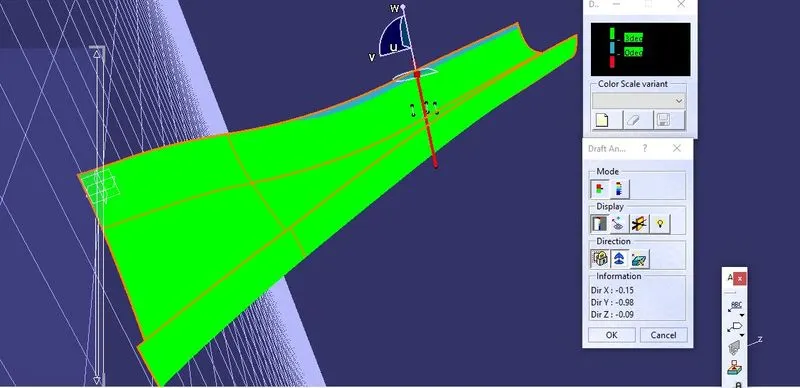
And draft analysis is done for the class A surface with respective to the tooling axis created.
CLASS B SURFACE :-
class b surface is the face which consists of the engineering features like dog house,locator,heat stakes,screw boss etc.
The class B surface is created by offseting the A surface for 2.5mm.
While the offset process there may create a patches which must be created manually by the commands like multisection, blend, fill, extract and extrapolate and trims.
Once these patches are filled.It may join together to form the B class surface.
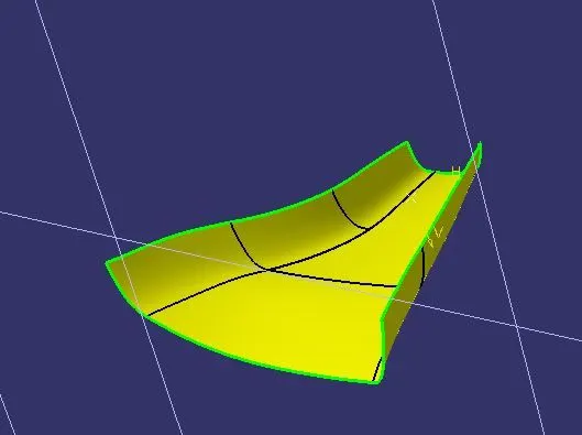
CLASS C SURFACE:-
The c surface is the to combine both A and B surface together.
These surface is created by sweep command with reference to the surface method with A class surface for an 90 degree.
And all three surfaces are joined together to form the final component.
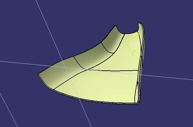
SOLID BODY:-
the solid body of the component is created by using close surface command.
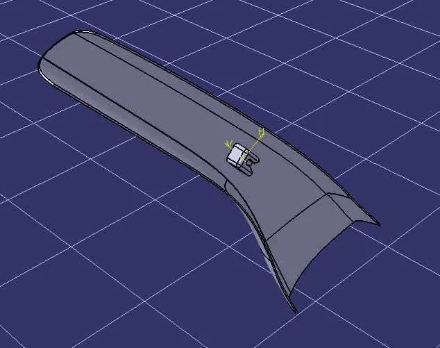
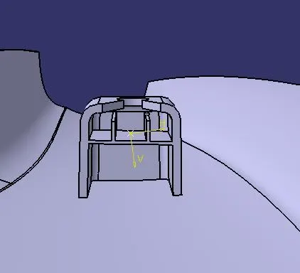
DOG HOUSE:-
the dog house is created by using the master section curves given as input.
A plane is created using the through two lines of the master section curves in the plane creation command.The referral point used here is created using the bisecting method.
The sketch for the dog house is extracted from the master section curves.
Those extraction lines are extrude for a distance and created as solid using thick surface command in part body workbench for an 2.5 mm towards inside as the sketch is outer of the master section.
The dog house body is assembled to the main body of the component.
And finally the draft analysis is done for the whole body using the tooling direction.