Week 8 - Challenge 4 - Bumper
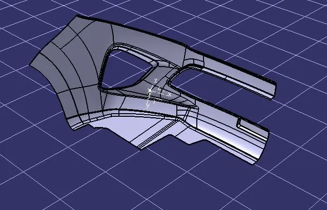
Steps followed to Create the Bumper Plastic component through the given Class-A surface. To begin with, the tooling axis for the given Class-A Surface should be created meeting the requirements of the draft angle and at the end perform the Draft analysis on the model.
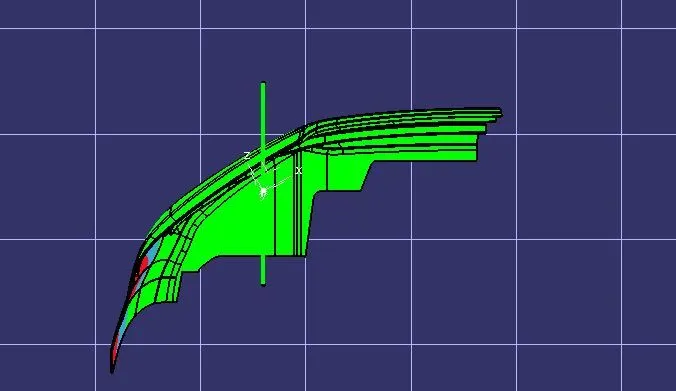
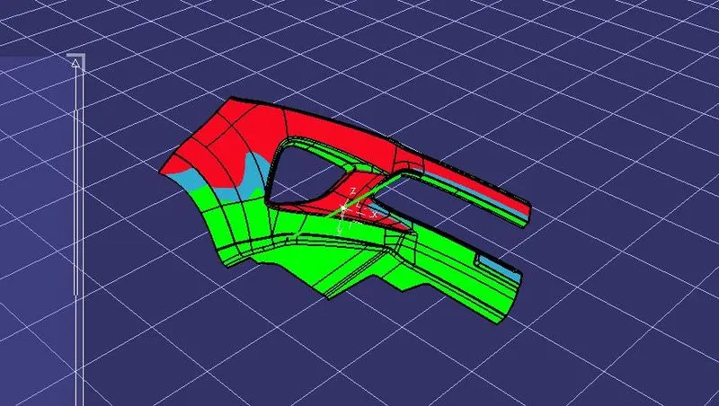
DRAFTING ANALYSIS
TOOLING AXIS
- By clicking on measure inertia,
- dialog box opens, first select the Class A surface
- and next select create geometry.
- where red point pop ups on the surface,to standardize the point click centre of gravity and axis system
- where your point created
- using the CG point, create a tooling axis in X,Y, or Z direction for the draft analysis.
- Bisecting method,
- creating a line by intersecting command on the components where you create a line on the projected curves.
- creating a line using the bisecting line method (by selecting the two lines, you can create the bisecting line).
METHOD FOR ANALYSIS
- you can use the line created by either of those above mentioned methods,
- align the compass to the tooling axis line.
- select the A class surface which you run the draft analysis.
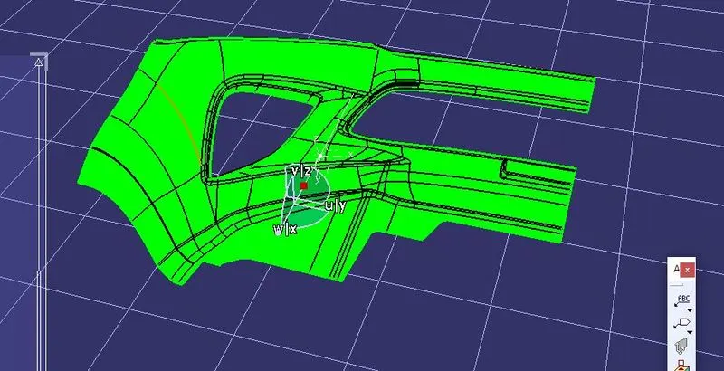
CLASS B SURFACE
- offset the Class A Surface by 3mm
- by offseting the surface, there may be some patched developed on the surface.
- we have to close those patches, by following commands like
- extract and multiple extract commands
- fill surface command
- split command
- trim command
- join command
- finally the join command is used to create a surface with a single sub element.
CLASS C SURFACE
- class c surface is created by sweep command
- surface is created using reference surface method in line to an angle of 90 and guide curves.
- due to connexity error, you cannot create using a boundary curve
- seperate surface is created and joined.
- all those A,B AND C are joined to form the final surface.
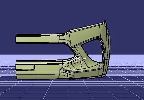
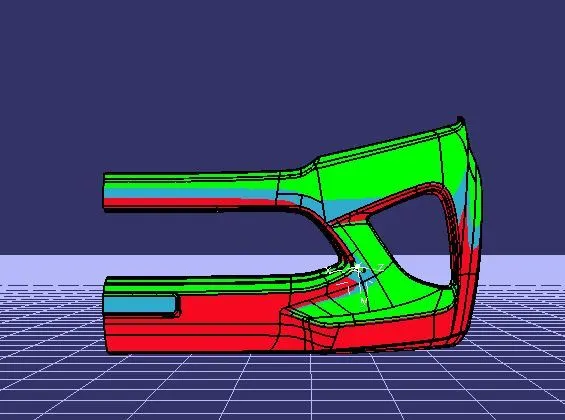
SOLID BODY IS CREATED USING CLOSE SURFACE COMMAND AND FINAL DRAFT ANALYSIS IS DONE ON THE SOLID BODY.