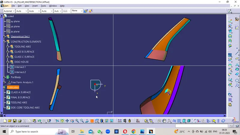
Week 9 - Project - A pillar Design with Master Section
OBJECTIVE:
Create the A Pillar Design with Master Section Plastic component through the given Class-A surface, and Create the B-side features Dog House using the Master Section.
STEPS FOLLOWED:
- Tooling Axis Creation.
- Draft Analysis of Class A surface.
- Creating Class B surface and Class C surface.
- Creating a Closed body of component A Pillar.
- Draft analysis for A Pillar Component.
- Creating the Sketches of Dog House profile based on the curves iven and make them as Solid Body using Part Design.
- Apply Draft angle ,Edge Fillet to the Dog House and Unitrim with Closed Body.
- Apply Draft Angle ,Edge Fillets to Final A Pillar Component.
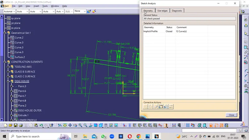
- Checking the Sketches of Dog House profile as per the given guidelines.
- Perform the Draft Analysis for A Pillar Assembly and for Dog House also.
Key Terms:
TOOLING AXIS:
- It is the direction of Mold's Core & Cavity moves.
- The Tooling Direction is basically the direction that the mold pulls apart.
- The mold is built in two separate pieces, Cavity side & Core side.
- The Core pulls apart from the Cavity and that's the Tooling Direction.
- The Line of Direction or Axis followed is Tooling Axis.
CLASS A SURFACE:
- Class A surface means Visible surface of the Component or part.
- It is the base reference to the creation of B & C surfaces that forms the Component.
- It provides the Aesthetic Appreance to the component.
CLASS B SURFACE:
- It is the mostly the Non-Visible Surface area
- It is the behind the Class A surface .
- It helps in the Parting surface creation.
- Flashes and Missmatches are done in the Class B surface , that will not distrub the Class A surface.
CLASS C SURFACE:
- It connetcs the Class A surface and Class B surface of the component.
- It also describes the Thickness of the Component.
DRAFT ANALYSIS:
- The Draft Analysis technique is used to analyze whether our Part model created is Manufacturable or not.
- Based on the Draft condition and Tooling Axis applied, Here the part should get easily removed from the Mold (Core & Cavity).
DOG HOUSE:
- It Avoid Sink Marks on Class A surface.
- It also arrests the Degress of fredom of component.
- Engineering features like snaps, locators , Screw Bosses etc. are mounded on them to increase their strength.
PROCEDURE:
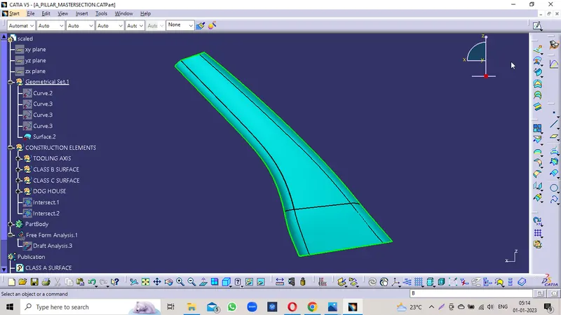
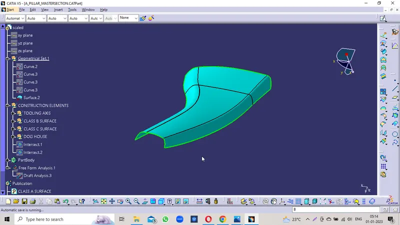
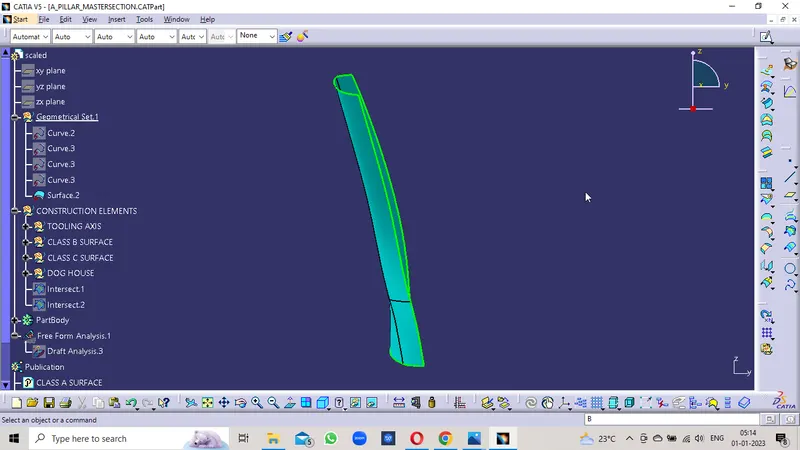
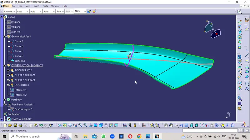
Checking the given Class A Surface.
- Checked the Class A surface is a Closed profile by using the Boundary command.
- The complete profile has only one Boundary at the outer edge without breakage.
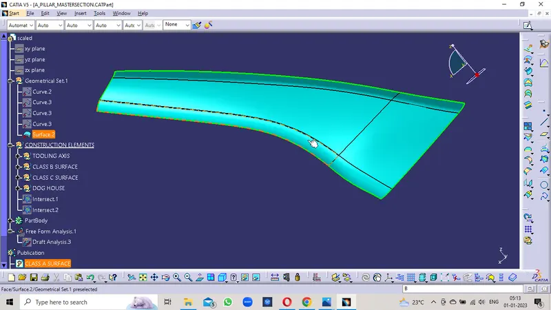
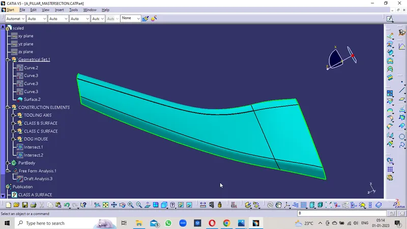
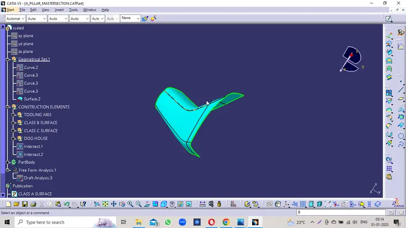
TOOLING AXIS:
- Tooling Axis can be Created by 3 methods mainly
- In thedirection of the X , Y , Z direction . Checking the given Surface in all the direction and where the maximum area of the component is visible, in that direction we can create a line and perform the Tooling Axis.
- if the given surface is not having the proper direction with X, Y , Z direction then the Line created to the Normal to the Maximum area of Plain Surface and Checked the Draft Analysis.
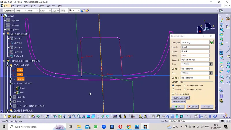
- In the Bisection Method we consider the Parllel surfaces and extract the lines of it and Bisect them at a point to get the Line that cleares the both the surfaces.
- If there were Multiple Parllel surfaces available then the each of them bisected and the Bisected lines are again Bisected to get the Accurate results and perform Draft Analysis.
- this Bisection Method gives the Better results but , it has the complexity issues , it is Recomended for the Uneven surfaces.
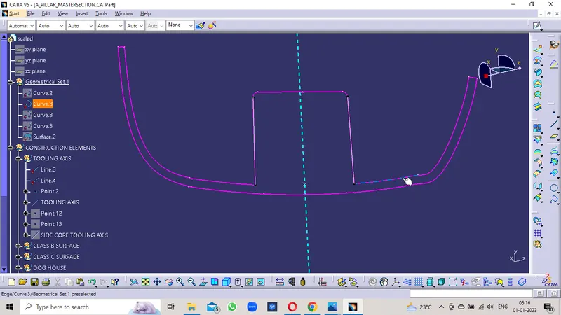
- But Here we have the B side Features like Dog House provided as input so we need to consider the sketch and perform the Reverse Engineering method for Tooling axis Creation.
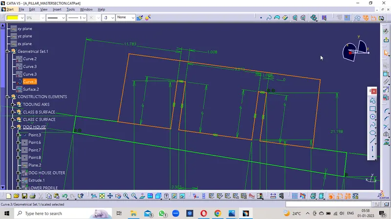
- Checked the curves given for the creation of B side features like Dog House for the Draft Direction used.
- Create a Midpoint on the Center of the Dog house .
- Extract the Parllel lines and bisect them at the Midpoint to the Line in Parllel direction.
- Check the Line and perform the Draft Analysis to the Class A Surface with minimum Draft angleof 3Deg.
- There should not be the Negative Draft angle on it.
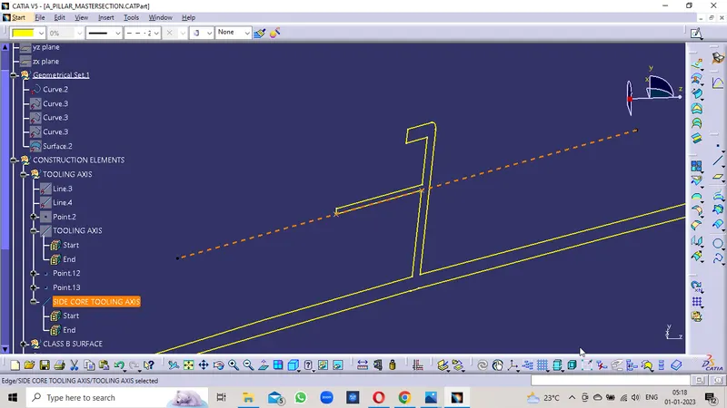
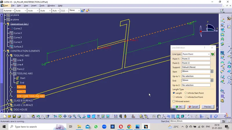
- Also create the Side Core Tooling axis by the Curves given.
- Check the perpendicular to the Main tooling axis and Side core tooling axis.
- Isolate the points and Lines extracted and used as a children from Curves Given.
Main Tooling Axis
Side Core Tooling Axis
DRAFT ANALYSIS:
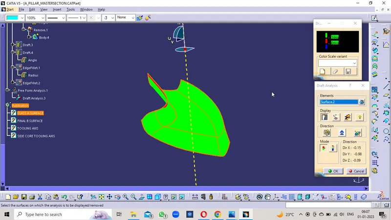
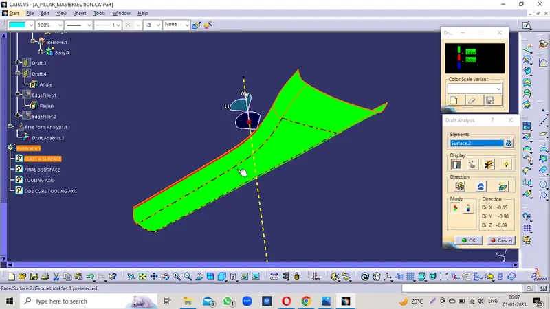
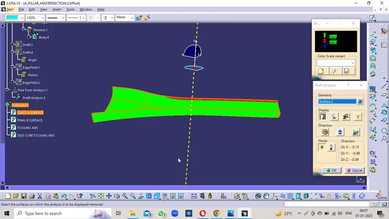
- Select into the Material Mode and Insert the Feature Draft Analysis.
- Select the Compass place in the Tooling Axis Direction and Activate the Compass , adjust the compass to the Tooling Axis Direction.
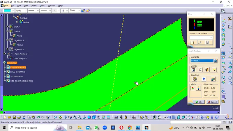
- Provide the Minimum Draft angle is 3Deg. If some patches are Created them provide draft angle as 2.9 or 2.95Deg.
- Select the surface So that the Green Area that is Draft angle is more than 3Deg angle and it is Manufacturable.
3Deg Draft angle
Small Patch with draft angle of 2.58 Deg minnimum value
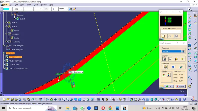
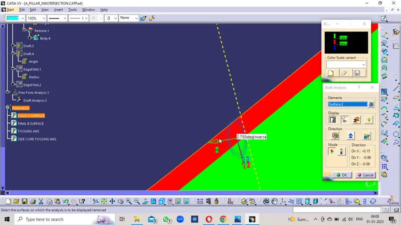
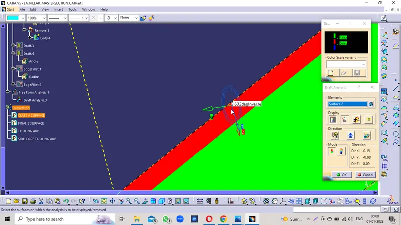
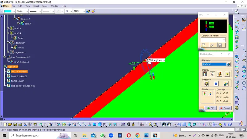
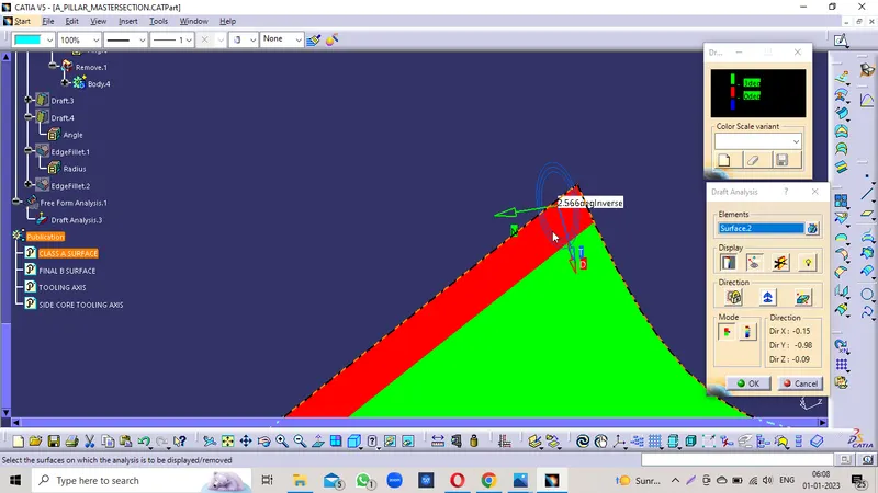
Cleares the Draft of 2Deg mostly
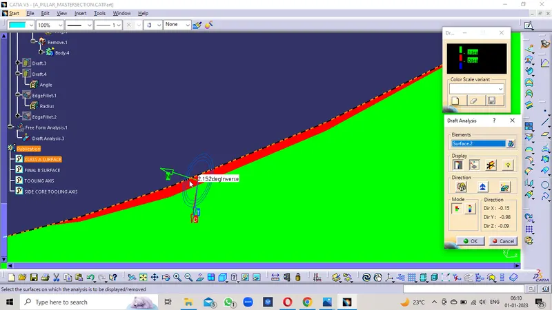
Cleares completely on 1.99Deg
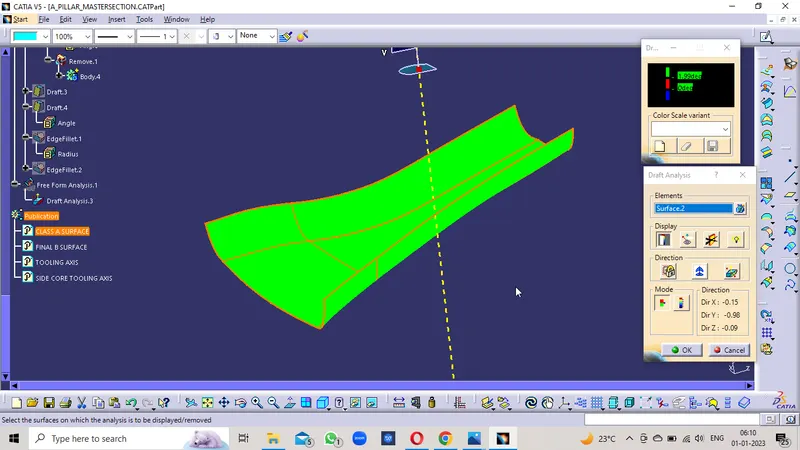
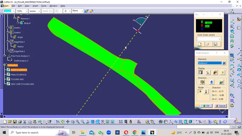

Creating Class B Surface:
Class B surface is mostly the not visible surface and it is the back of the Class A surface.
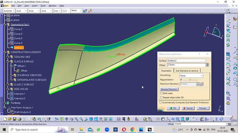
- Offset the Class A surface for 2.5mm (Thickness of Component is 2.5mm).
- The offset surface has the Patches that the minimum fillet value placess cant be offset.
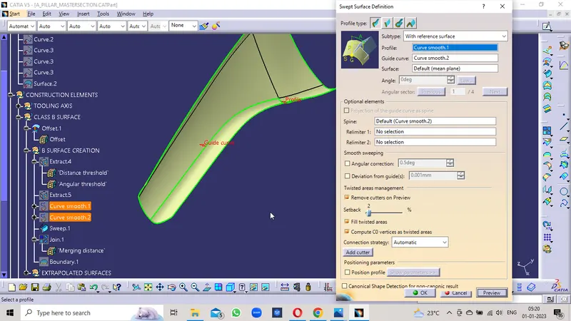
- The Patch Here created is the Stylized fillet.
- It is created by using the Sweep Comand with the Reference Surface and Guide curve that are on the offseted Class A surface.
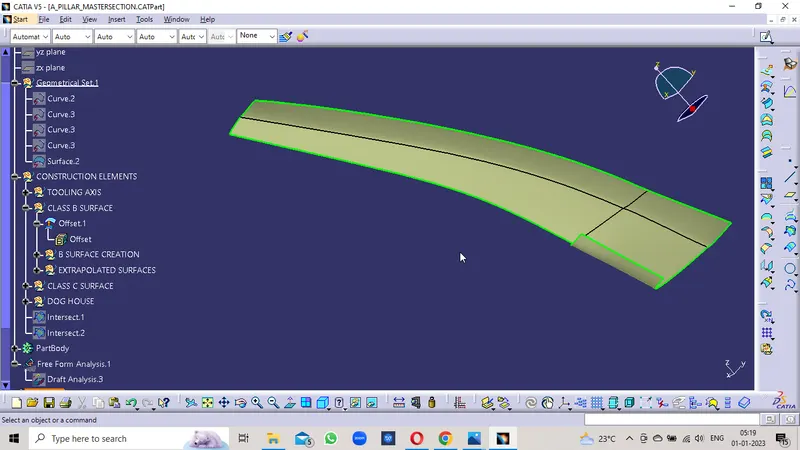
- Now Join the Offset surface with the Sweep surface with the Maximum merging distance as 0.003mm to avoid the manufacturing defects on component.
- Cross checked gap between the two surfaces Class A and Class B surfaces found that to be 2.5 mm.
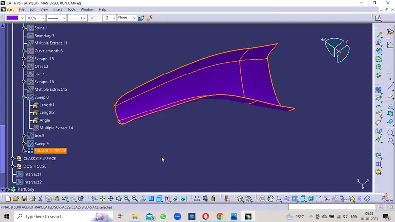
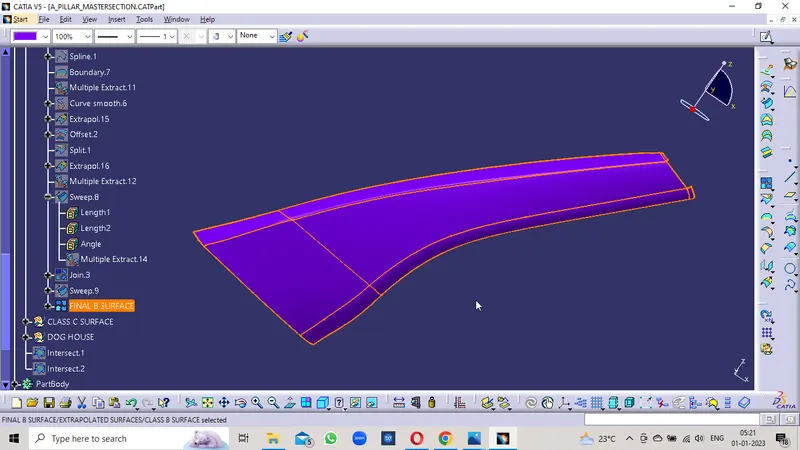
- Extrapolate the B surface on all sides that it can be easily trimed with Class A & C surface.
Sweep Surface
Extrapolated B surface
Class C Surface:
Class C Surface is that connect the Class A Surface and Class B Surface.
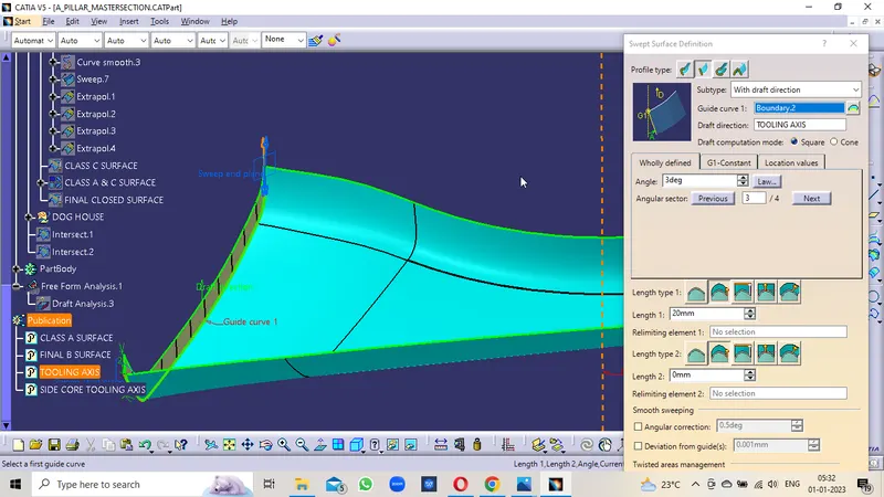
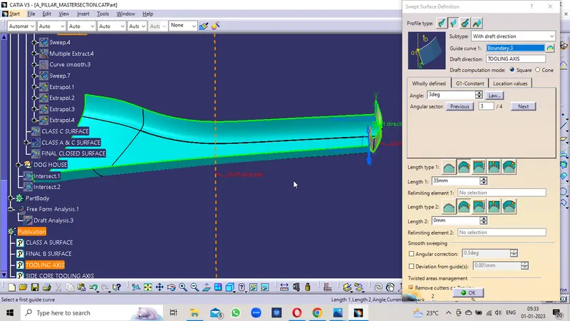
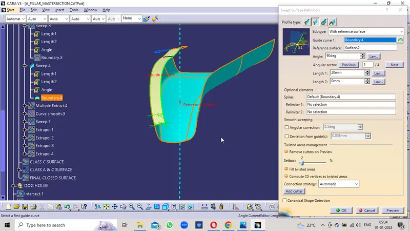
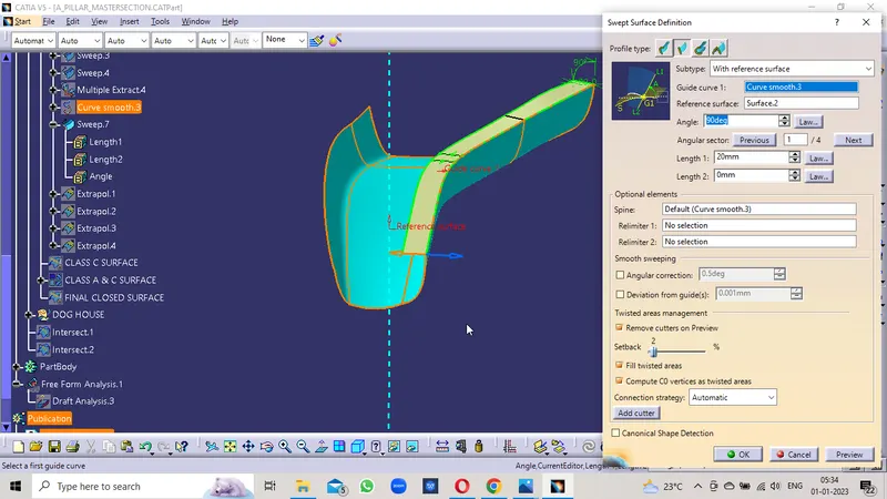
- Create a boundary on the Class A surface at the individual corner and then Sweep it individually to avoid the patches.
- The C surface Parllel to the Tooling Axis then it is created by using the Draft Direction with the 3 Deg Draft minimum.
- The Direction of Draft is at the Outside Facing one , it helps the Parting line creation on the B surface and it reduces the defects created on Class A surface and also Flashes are formed on Class B Surface.
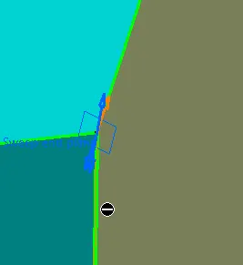
- The C surface is Perpendicular to the Tooling axis then it created by the reference surface method
- By using the Sweep Command with the reference of Class A surface and angle of 90Deg to it on the selected Boundary.
- The length of the Class C Surface is 4mm minimum, so that it will be trimed easily with Class B Surface.
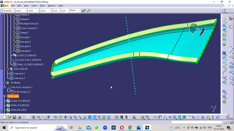
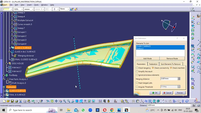
- Then the individual surfaces of Class A and Class C are Joined by using the Join Command.
Draft Direction
With Reference surface
Class A and C Surface
Closed Surface:
- Trim the Class A and Class C joined surface with the Extrapolated Class B surface.
- The Trimed surface is formed.
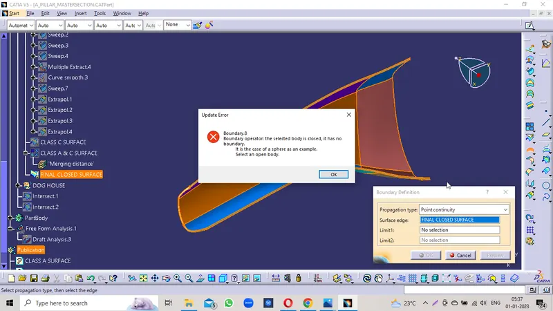
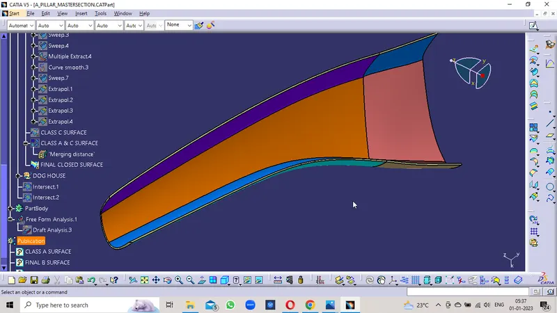
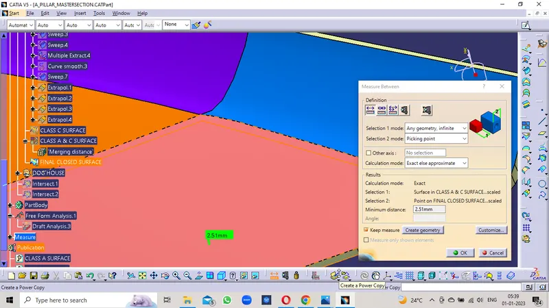
- Created a Boundary on the Trimed Surface so that it inssures that no boundary formed. Confirms that it is completely closed.
- By using the Closed surface Command in the Part Body Design to the surface body.
- Now the Solid Body is formed.
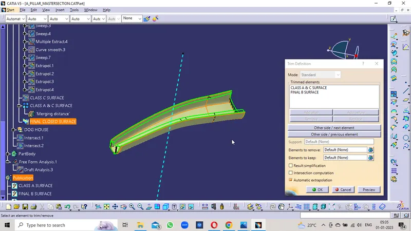
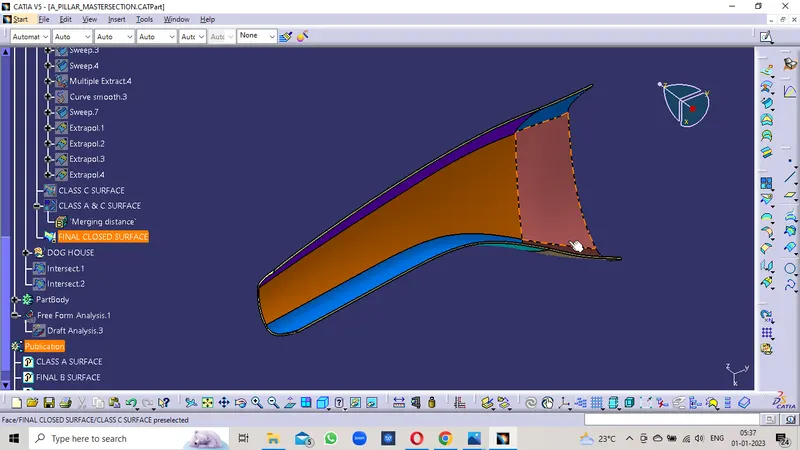
Closed body check boundary condition
Thicknes Check
Dog House:
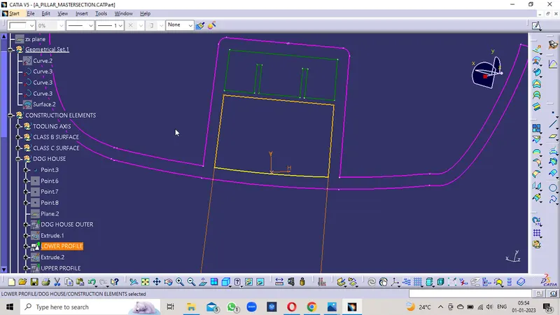
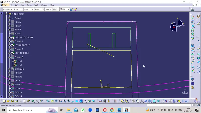
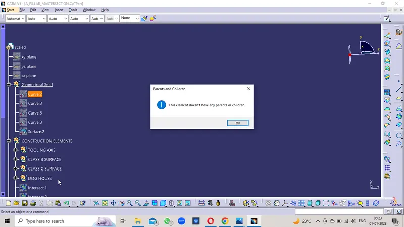
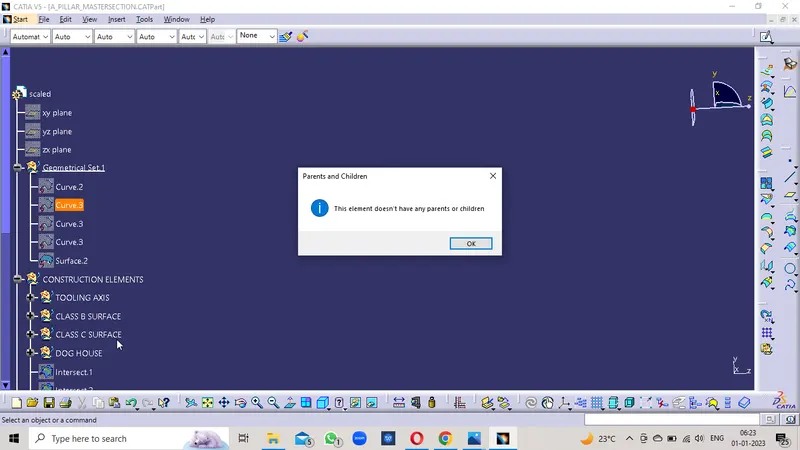
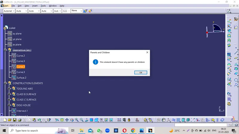
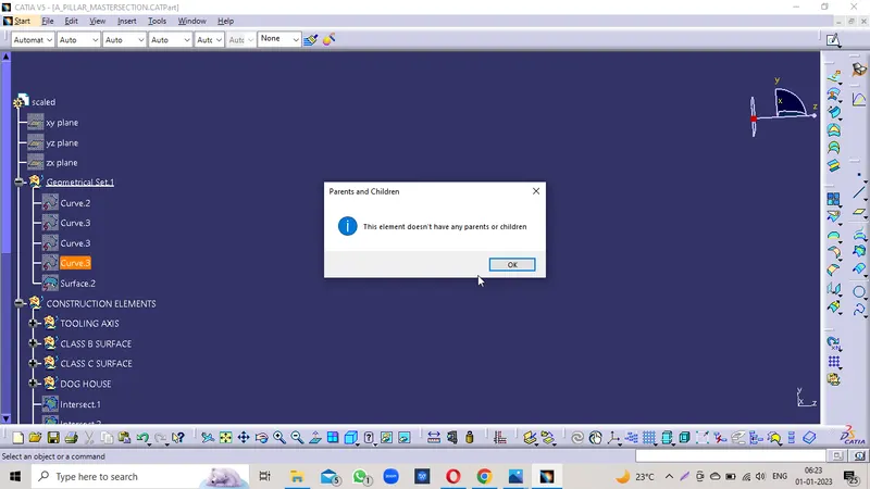
- Project the given curves and isolated them so that there is no Parent Children Relation between the Input Curves and Part body and also with the Sketches also.
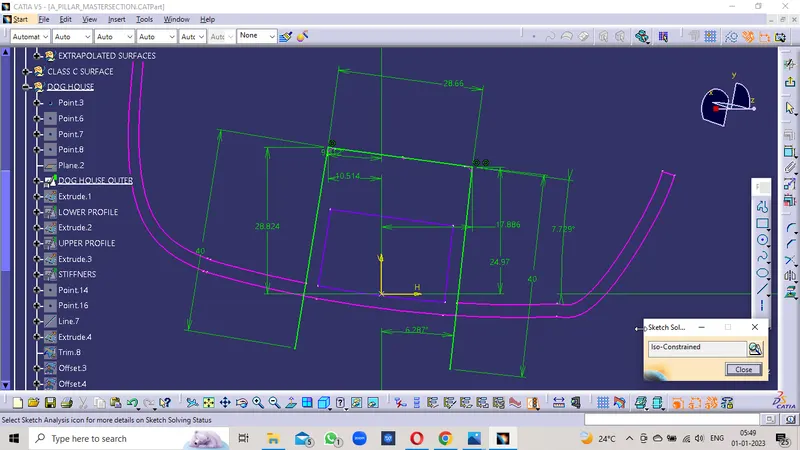
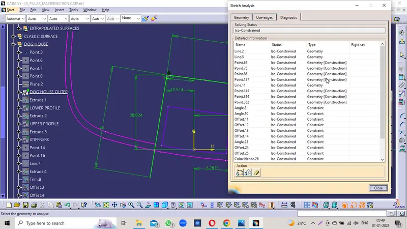
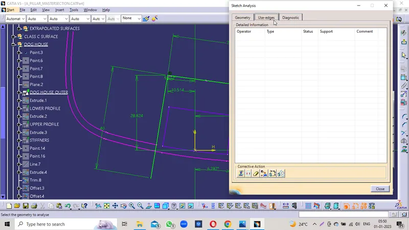
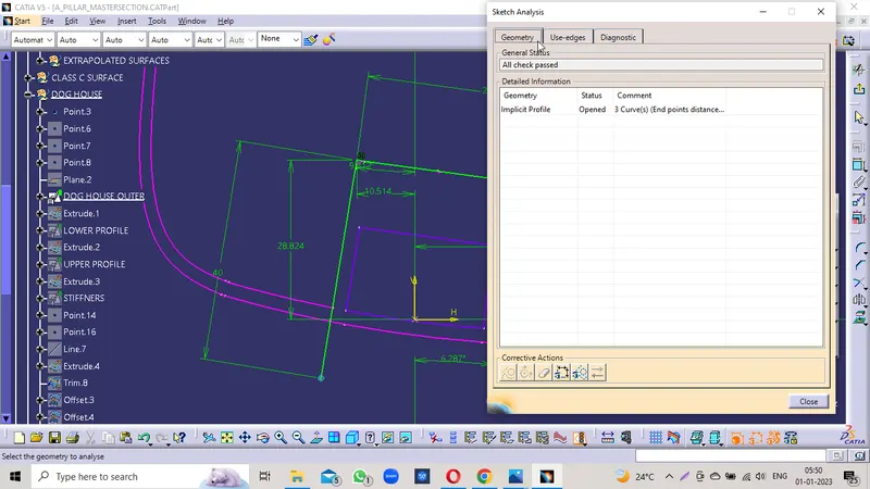
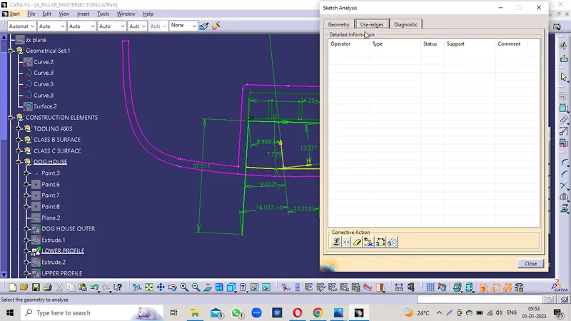
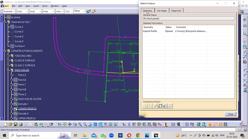
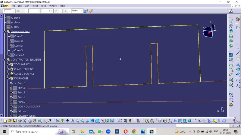
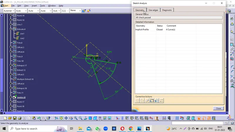
- Create Sketch of Dog House And Iso constrained it in the Position Sketch.
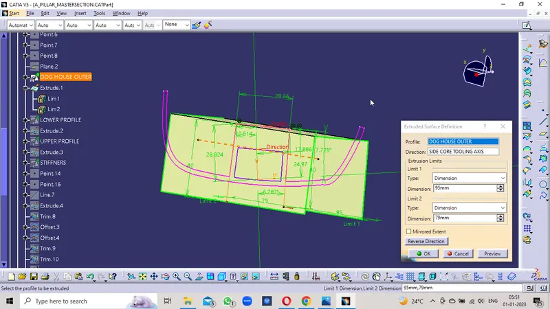
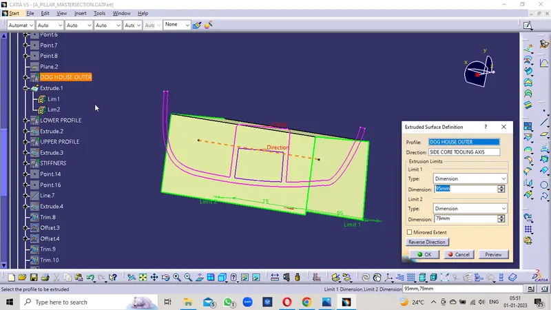
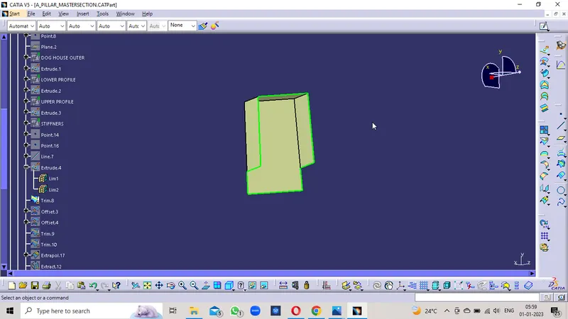
- Extrude It to the certain height.
- Offset the base plane and Trim with the Extruded Profile.
- Splitthe Inner Profiles to the Dog house so that it will be in the proper shape.
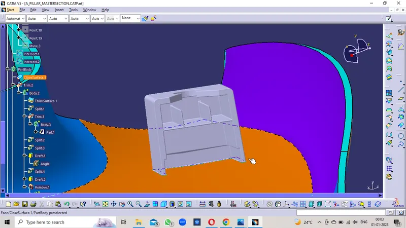
- Now Thick Surface The Closed Profile and Split up the Required Width .
- Now Create the Sketches of the Rib Profile , apd it and extend the bottom section so that we can easily Unitrim it with the Dog house profile
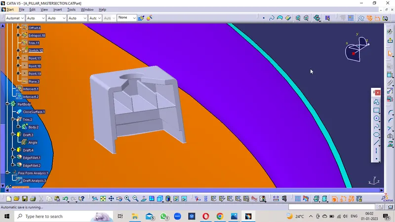
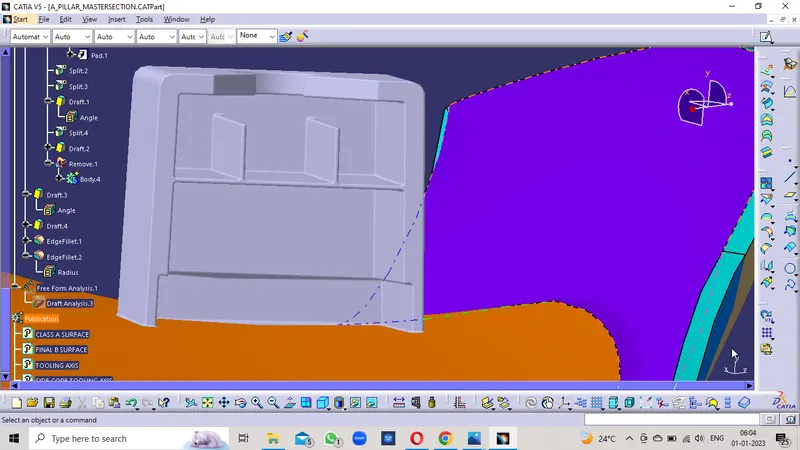
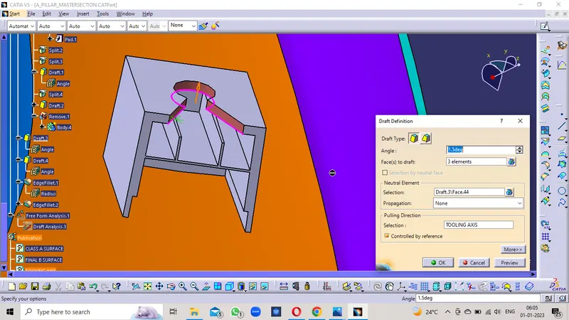
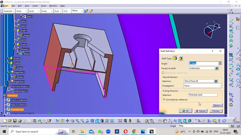
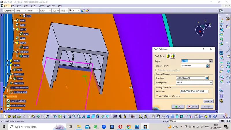
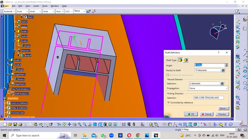
- Now Prowide The Draft Angle of 1.5Deg outer and 0.5Deg inner with reference as Back side of profile as neutral element.
- Now create a cut profile at the bottom side and split it for the Required width of 1mm and at a height of 5mm.
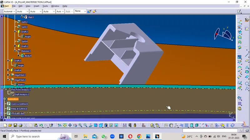
- Create the Push pin Locator profile on the top surface of the Dog house and remove the profile part on the Dog house component.
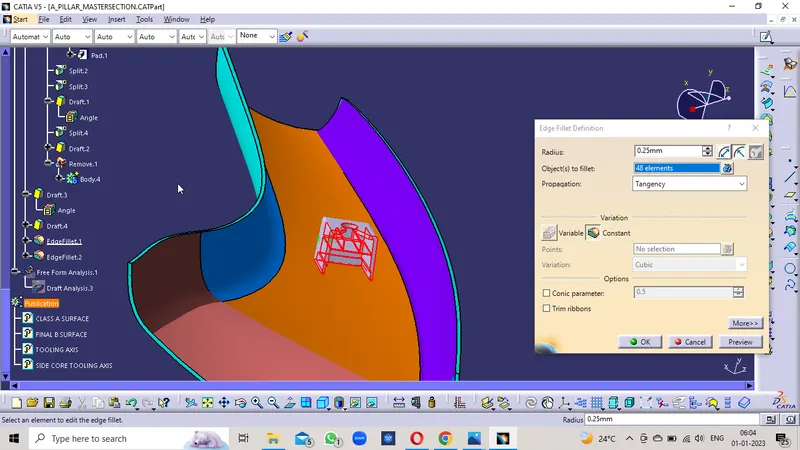
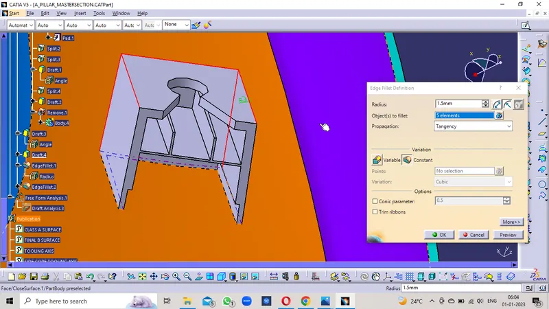
- Now provide the Draft angle , Minimum fillet value to it.
- Now prowide the Fillet Radius as 1.5 mm outer and 0.25 at the cut profiles amd inner profiles.
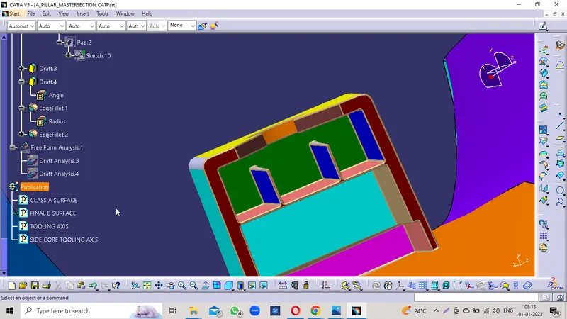
- Now perform the Draft Analysis for Dog House and For Component.
Given Inputs
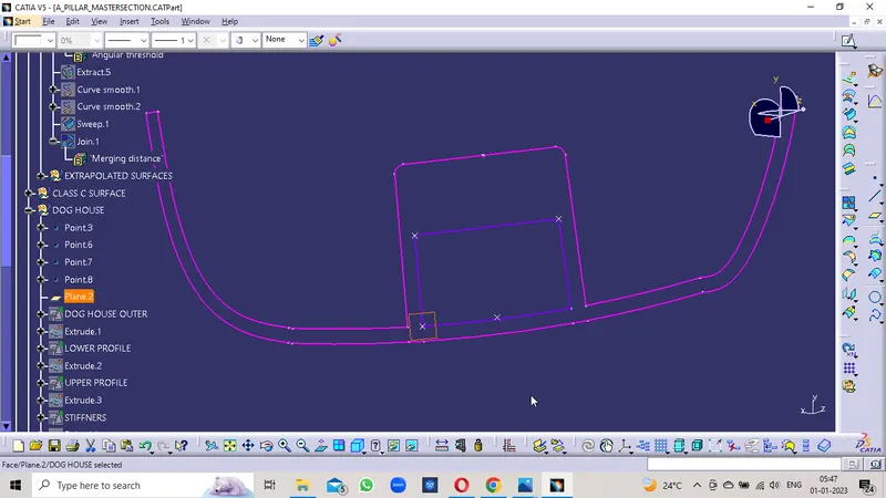
outer profile of Dog House
inner profile of dog house
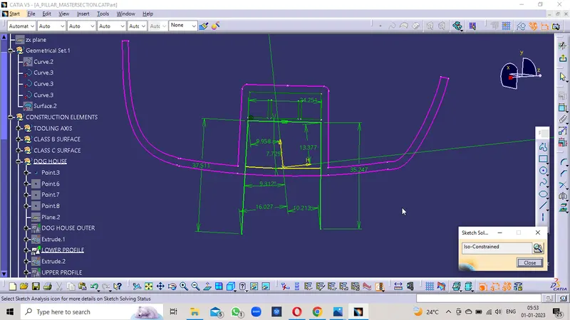
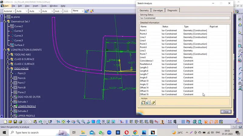
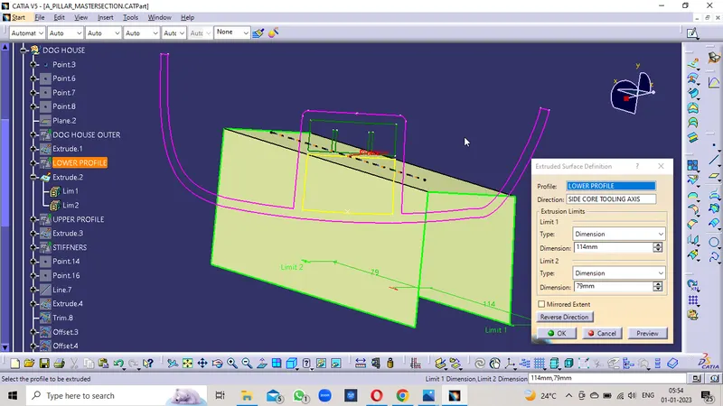
upper profile of Dog House
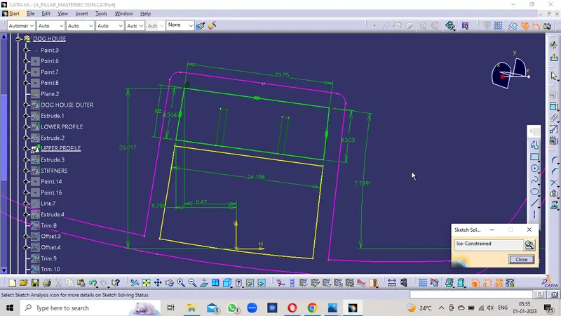
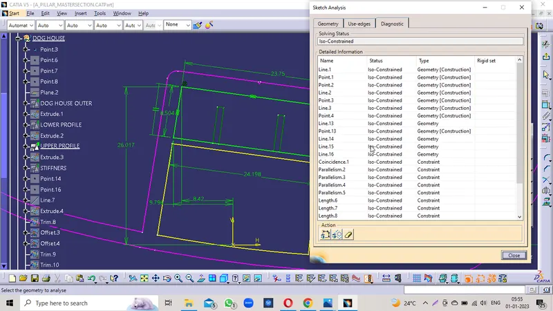
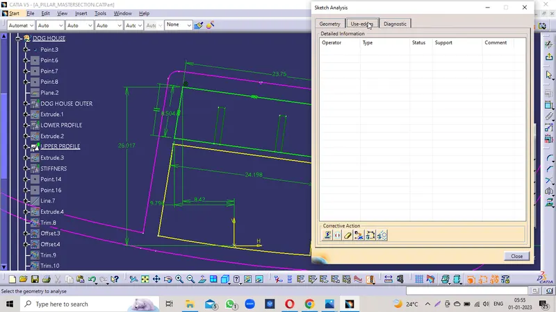
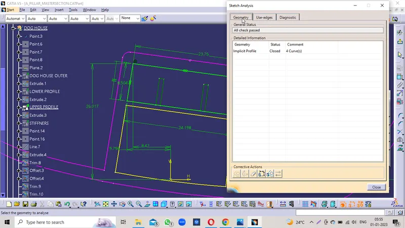
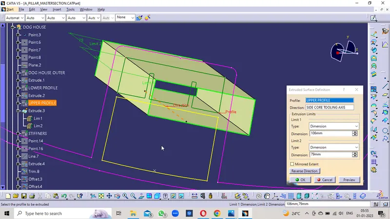
Sketch profile match with inputs
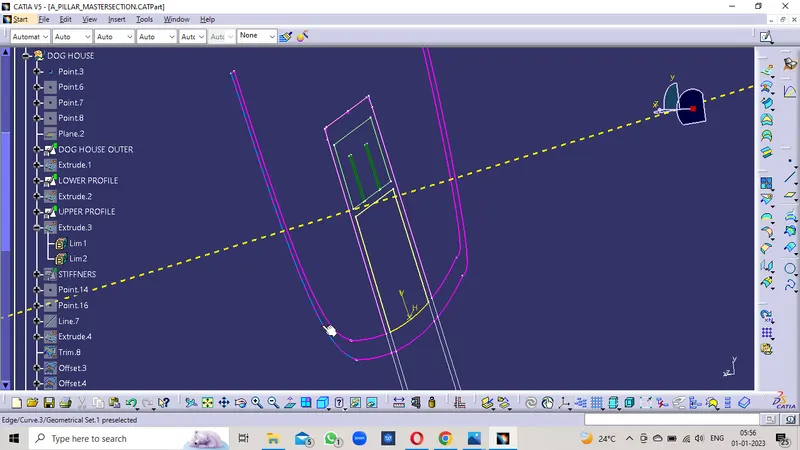
Stiffner Profile
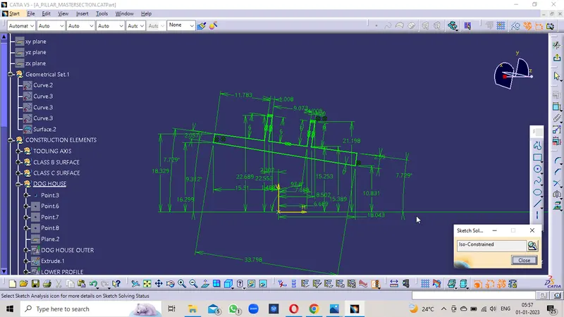
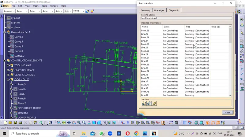
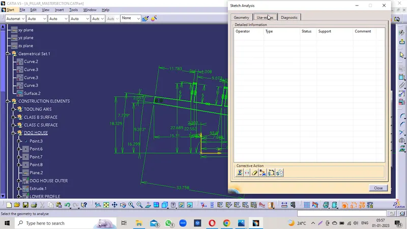
profile matching with input
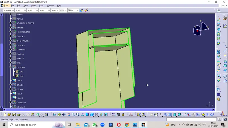
Push pins profile on top
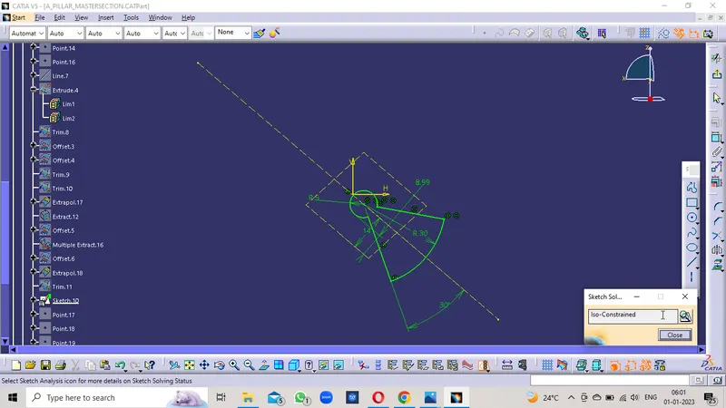
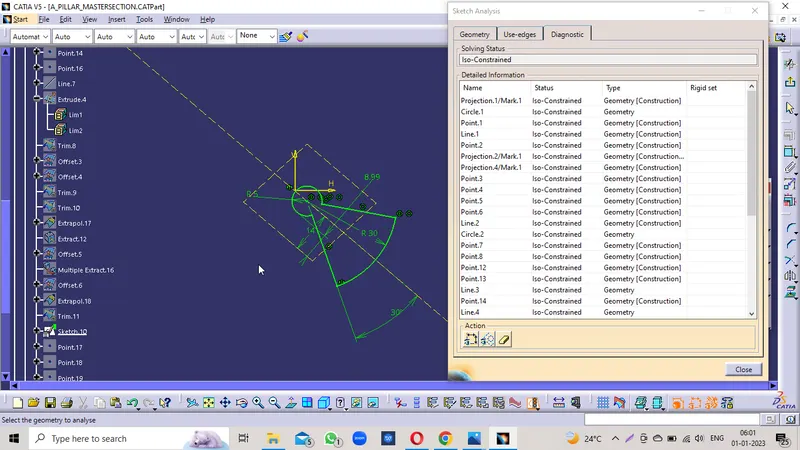
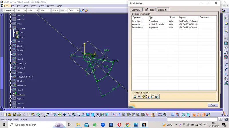
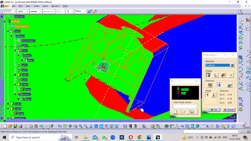
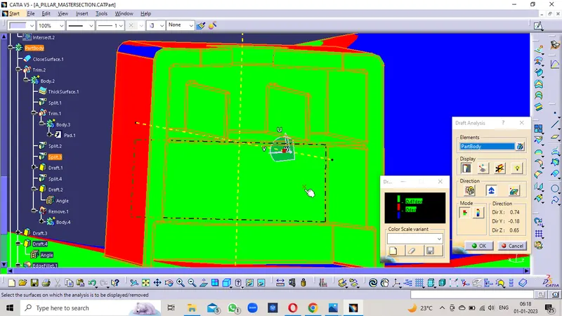
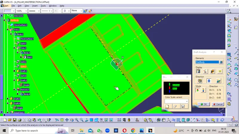
DRAFT ANALYSIS:
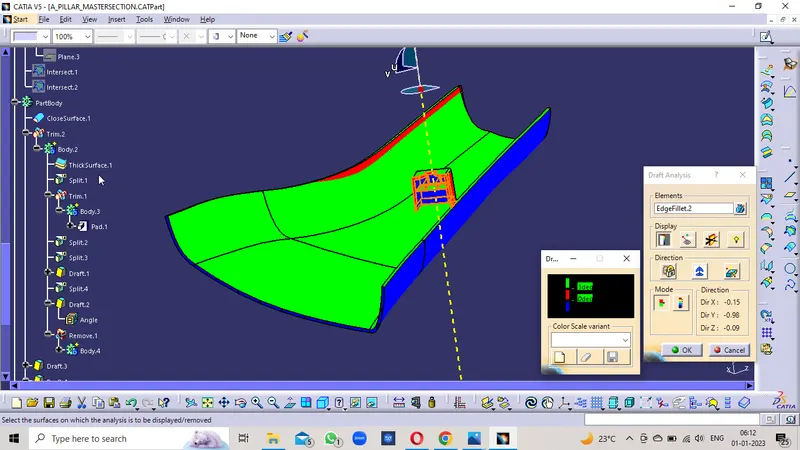
- Select the Draft Analysis to the ClOSED SURFACE.
- Select the Axis and place the Axis line along the Tooling Axis direction.
- Select the Draft angle degree as 3Deg minimum.
- Selected the Surface and found in Green Colour in all the surface area in the Draft Direction.
- Checked the inversion of Drafting to the Core side and Cavity side.
- Cross checked the angle of draft at all surfaces and found that is more than 3 deg.
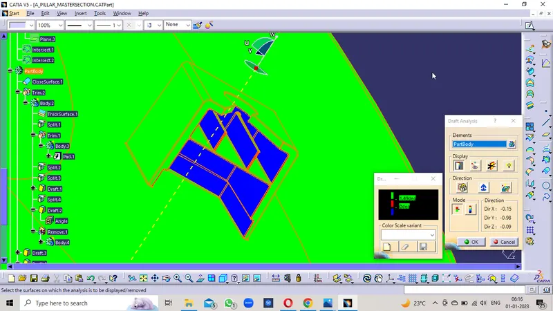
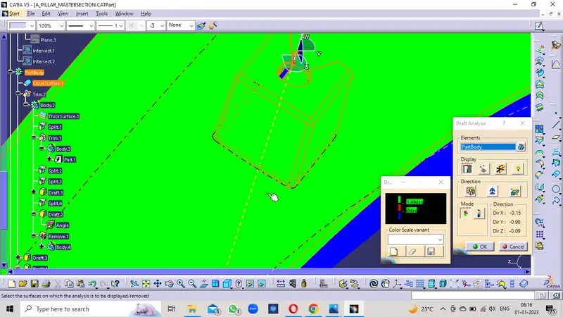
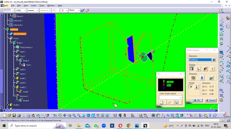
- Checked the Draft Angle as 1.5Deg for the Dog House Exterior in the Tooling Axis direction.
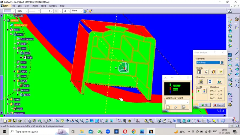
- Now Changed the Compass to the Side Core Tooling Axis and activated it.
- Checked the Draft Analysis for the Interior of the Dog House clearing the minimum of 0.5Deg of Draft Angle.
Door Ttrim Draft Anlysis of 3Deg Draft Angle
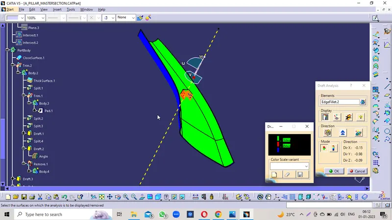
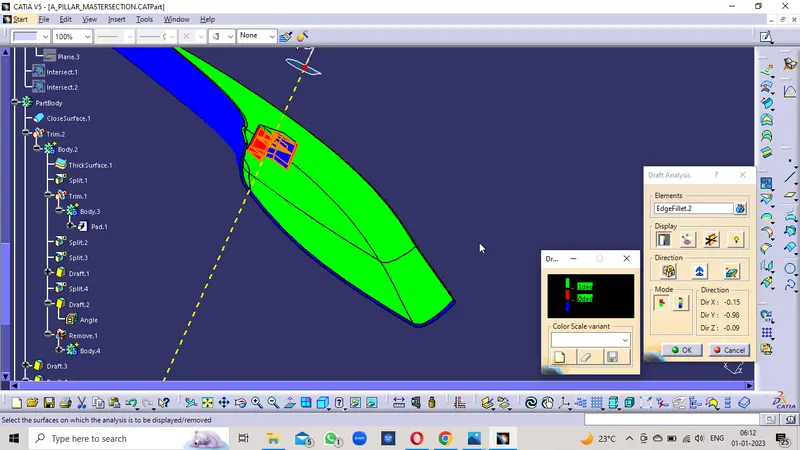
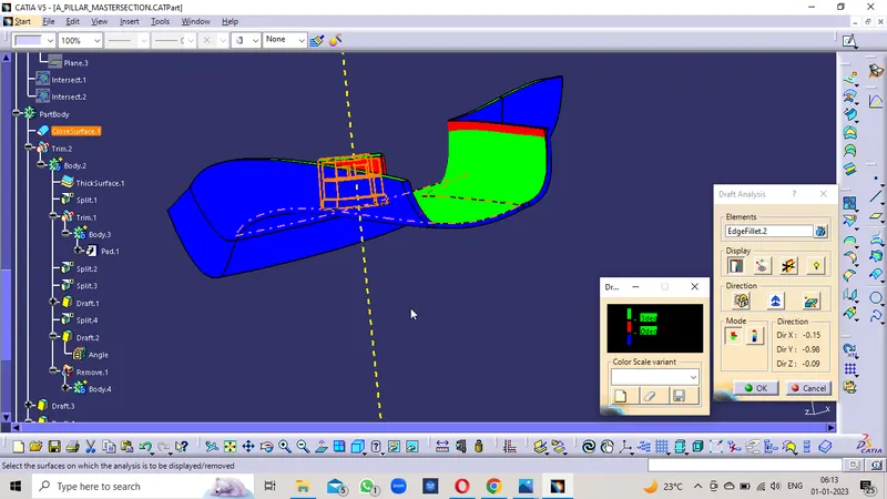
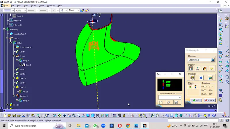
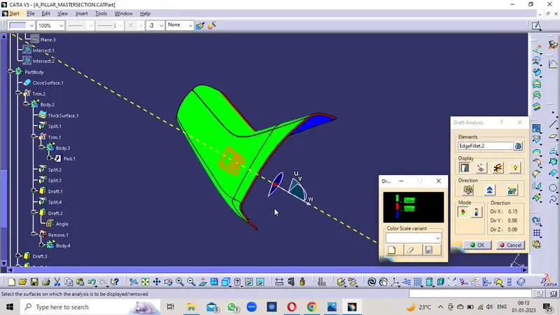
Draft angle of 2.95Deg
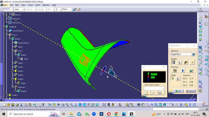
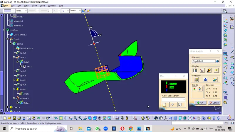
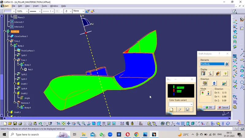
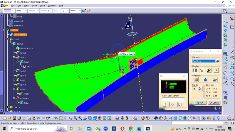
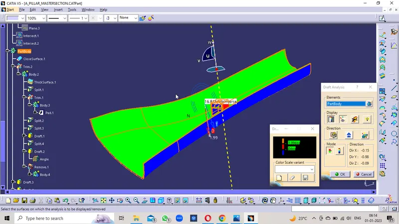
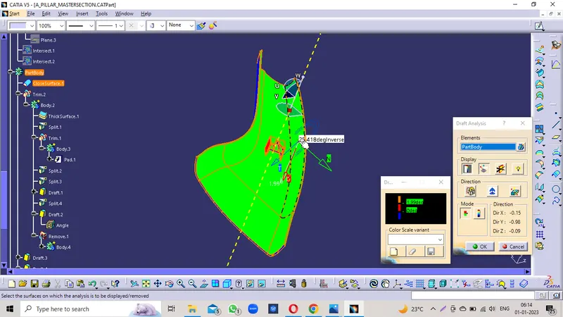
Draft angle of 1.99 Deg completely cleares of plastic component
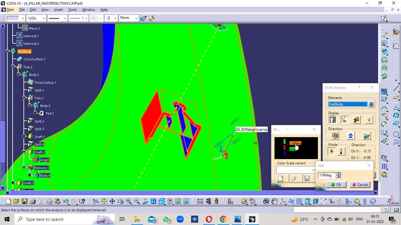
Dog House Outer profile with 1.5 Deg Draft angle with Manin Tooling Axis
Dog House Inner side of 0.5 Deg (0.47Deg) with Side core Tooling axis
Intersection Profiles:
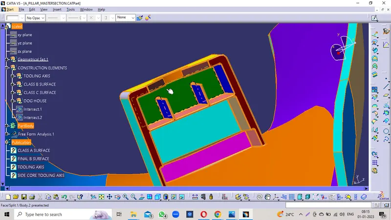
- Create an intersection of the Part Body at the Planes Used to create the Sketches
- The Profiles should match as the Given Input Curves.
- Check the Interscetions with the Input Curves for any changes
- It matches with the profile and the small deviation of the draft angle and fillet radius.
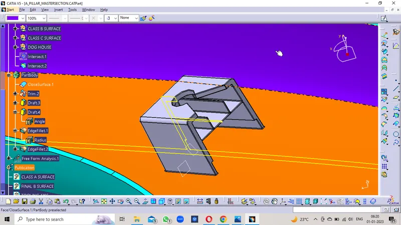
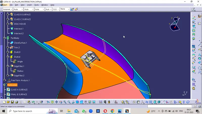
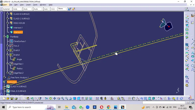
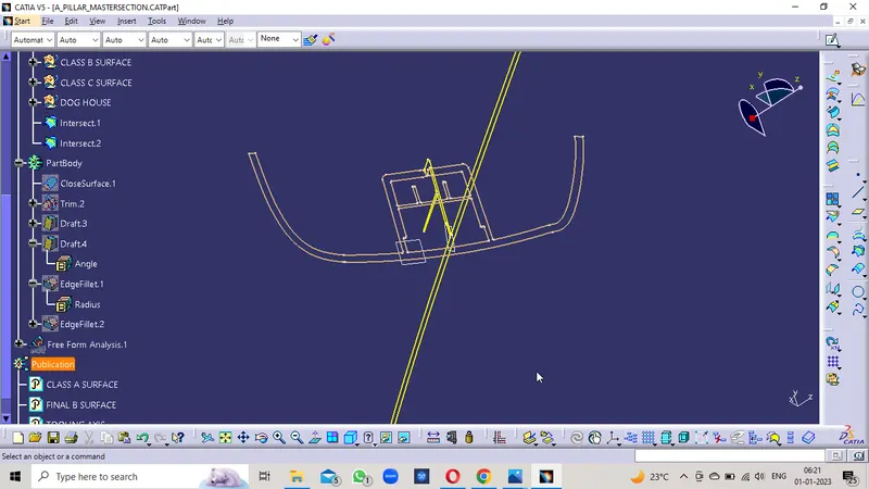
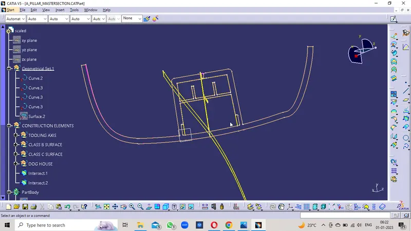
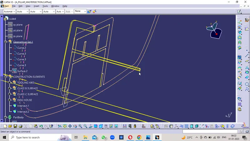
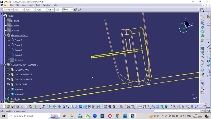
Now check the Parents and Children for the given Input Curves of the Master Section , so that there should not be any relation to the part body or the sketches of it.
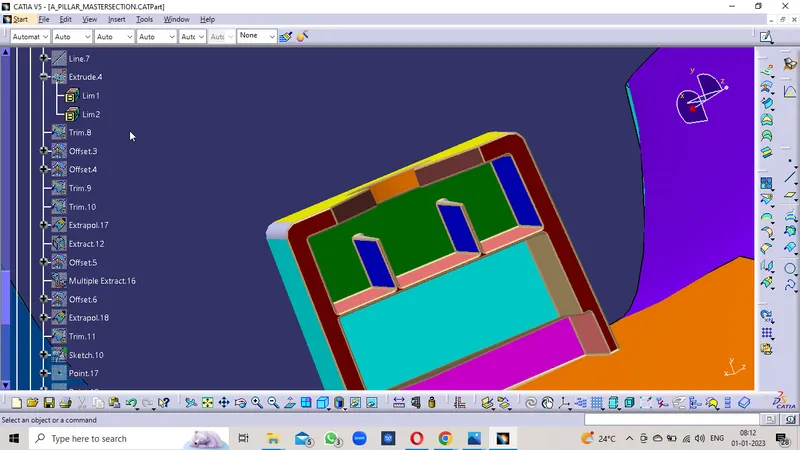
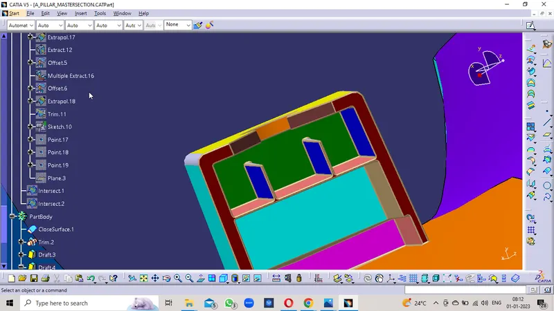
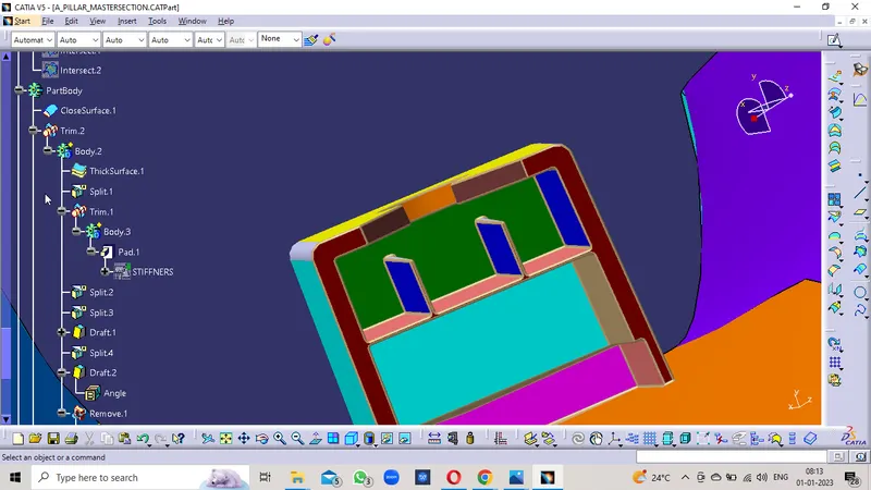
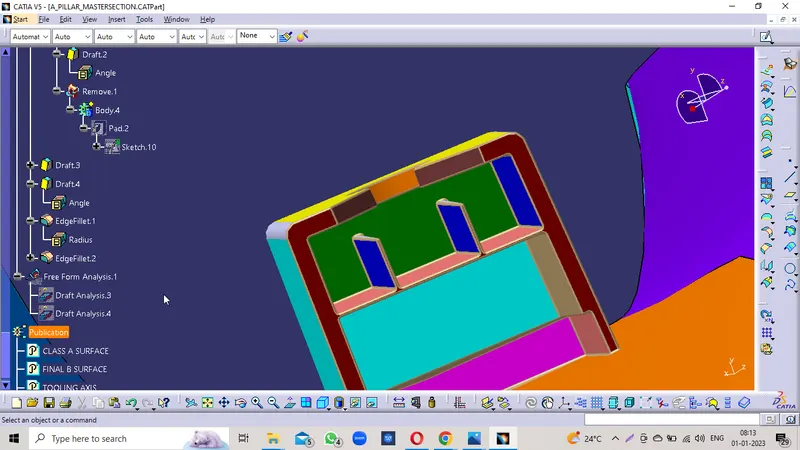
Tree Structure
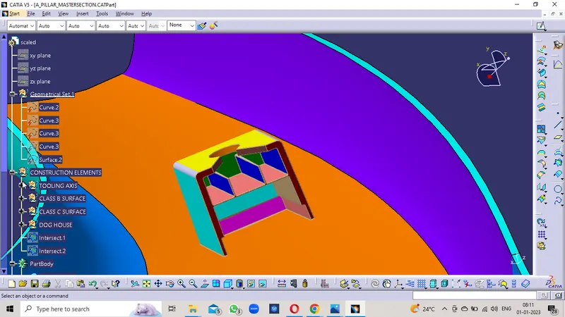
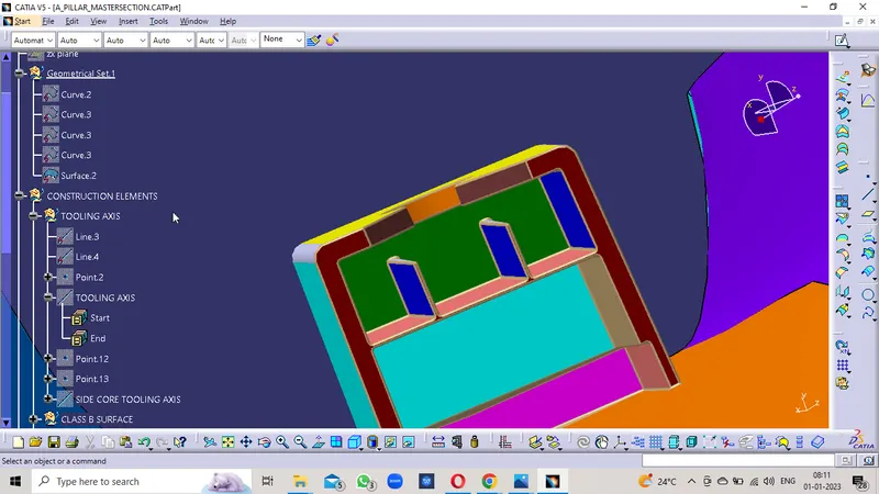
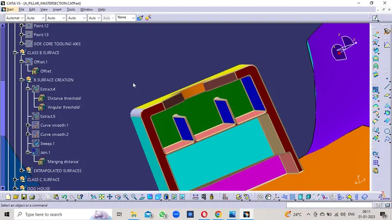
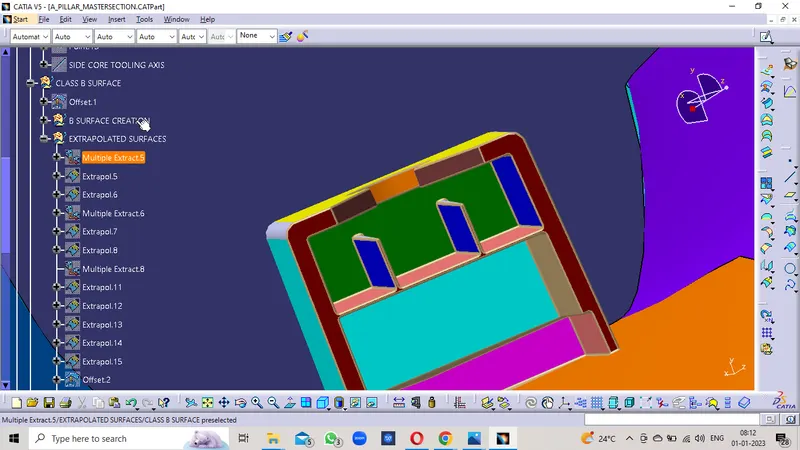
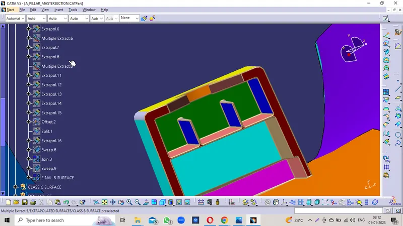
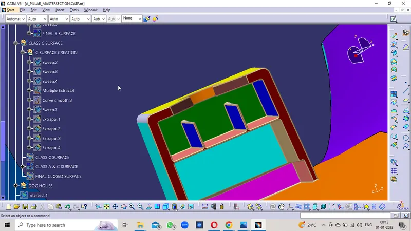

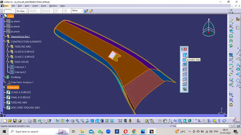
Isometric View
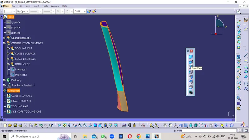
Front View
Back View
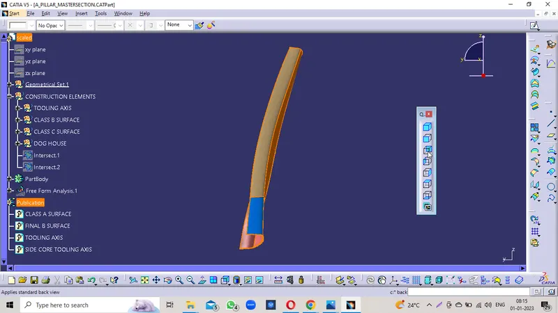
Left View
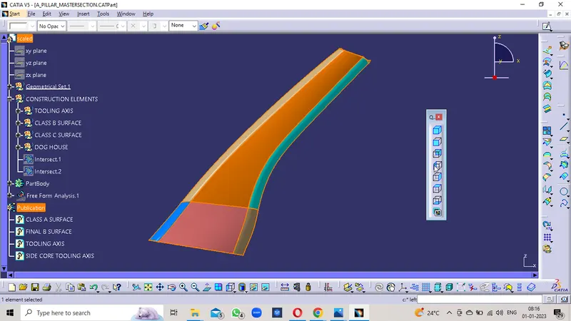
Right View
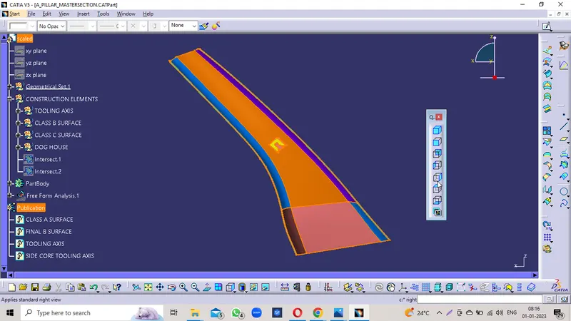
Top View
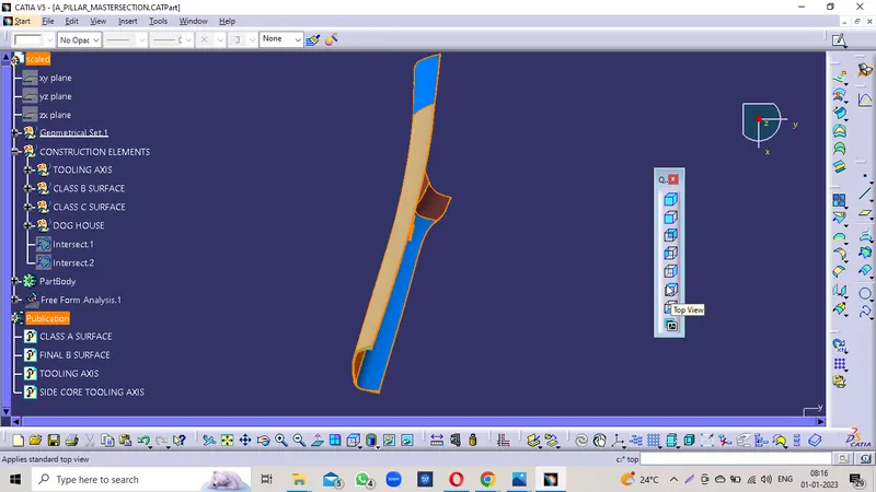
Bottom View
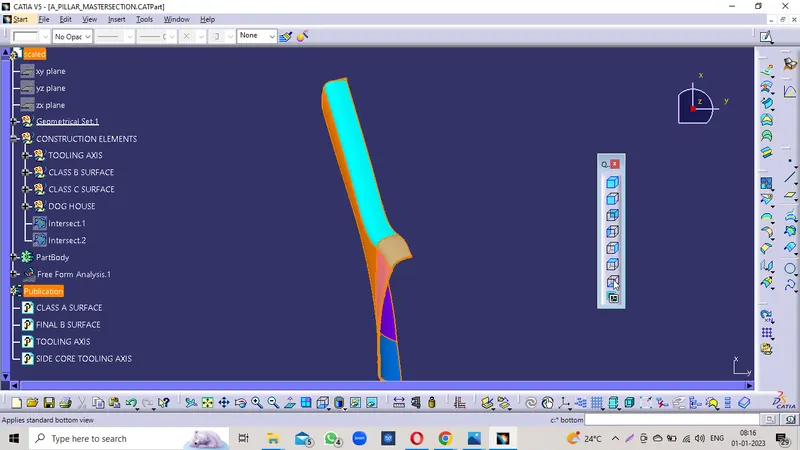
Multisection View