Week 8 - Challenge 3 - Coin Holder Design
OBEJECTIVE:
Create the Coin Holder Plastic component through the given Class-A surface. To begin with, the tooling axis for the given Class-A Surface should be created meeting the requirements of the draft angle and at the end perform the Draft analysis on the model.
Commands used mostly are Extract, Multiple Extract, Untrim, Join, Trim, Extrapolate, Offset.
PROCEDURE STEPS:
- Check the given Class A surace is Closed or Open surface by using Boundary command
- Craete the Tooling axis with the help of side wall surfaces.
- Draft analysis is carried out for given Class A surface wheather check wheather it is feasable or not.
- Create the Class B surface using the Class A surface at a Offset distance of 2.5mm ( Thickness of component is 2.5mm)
- Give the Fillets values to the edges that arre on the class A surface with respect to the thickness of component is 2.5mm
- Create Class C surface that connects the Class A and Class B surfaces by using sweep command with reference of Class A surface.
- Join the Class A surface and Class C surface and then Trim with Class B surface.
- Check wheater it is a closed surface or not by using the Boundary command.
- Create a Closed Part Body by using the Closed Surface command in Part Body Design.
- Do the Draft analysis for the Closed Part Body with the help of Tooling Axis , then it should clear the both Core side and Cavity side and the Draft angle should be minimum 3Deg.
PROCEDURE:
1. Checking the given Class A Surface.
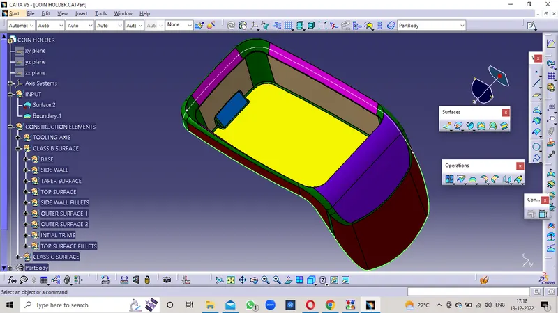
- Joined the surfaces by using the Join Command for patches in surfaces. The minimal distance is 0.001mm.
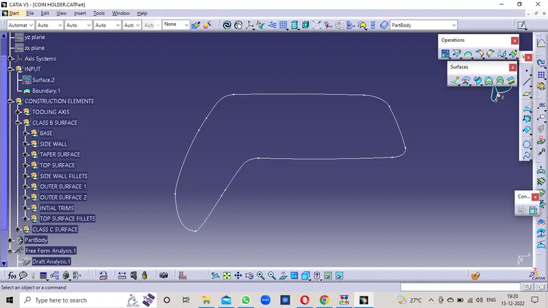
- Checked the Class A surface is a Closed profile by using the Boundary command.
- The complete profile has only one Boundary at the outer edge.
2. TOOLING AXIS & DRAFT ANALYSIS
- Analyised the given Class A surface of all Posibilites of Direction.
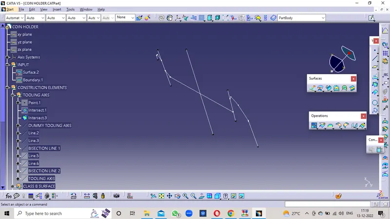
- Created a mid point in base plane and draw a line as a Dummy Tooling Axis.
- Created a Intersection in the both Direction of the Class A surface.
- Created lines along the intersections.
- Bisected the lines to form the new line at the mid point of plane in the direction of Dummy Tooling Axis.
- The Intersected line as the Tooling Axis and Publish it.
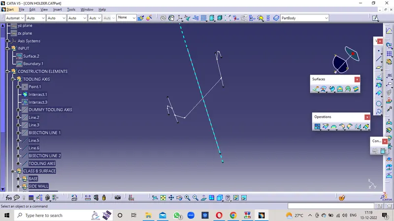
3. DRAFT ANALYSIS of CLASS A SURFACE:
Draft analysis is carried out to check wheather given Class A Surface is feasable or not for creating Plastic Component.
- Select the Draft Analysis to the Class A Surface.
- Select the Axis and place the Axis line along the Tooling Axis direction.
- Select the Draft angle degree as 3Deg minimum.
- Selected the Surface and found in Green Colour in all the surface area
- Cross checked the angle of draft at all surfaces and found that is more than 3 deg.
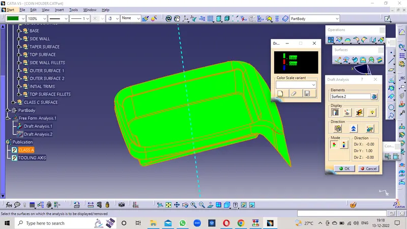
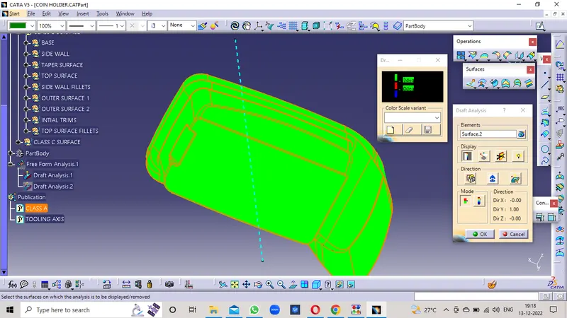
4. Creating Class B Surface:
Class B surface is mostly the not visible surface and it is the back of the Class A surface.
- Extract the base plane and other surfaces separately.
- Untrim them and Extrapolate it to require length on all surfaces.
- Offset it the surfaces to the 2.5mm in the back direction of Class A surface
- Trimed the offseted surfaces in the proper order to form the base shape as the Class A Surface.
- Cross checked gap between the two surfaces found that to be 2.5mm.
5. Fillets:
- The finished surface is given the Fillet vallues.
- The thickness should be added or subtracted to the fillet value based on the direction of it.
- Checked the remaning surfaces that all are filleted and no sharpeges found
- The minimum fillet radius is given that 0.5mm.
6. Class C Surface:
Class C Surface is that connect the Class A Surface and Class B Surface.
- Create a boundary on the Class A surface.
- By using the Sweep Command with the reference of Class A surface and angle of 90Deg to it.
- The thickness or length of the Class C Surface is 4mm.
7. Class A and C surface:
- Class A surface and Class C Surface are joined by using the join Command.
- Class B surface is extrapolated at its boundry for the trim
- Now the Joined Class A & C Surace is trimmed with the Class B surface.
8 & 9 Closed Surface:
- The Trimed surface is formed.
- Created a boundary on the Trimed Surface so that it inssures that no boundary formed.
- Confirms that it is completely closed.
- By using the Closed surface Command in the Part Body Design to the surface body.
- Now the Solid Body is formed.
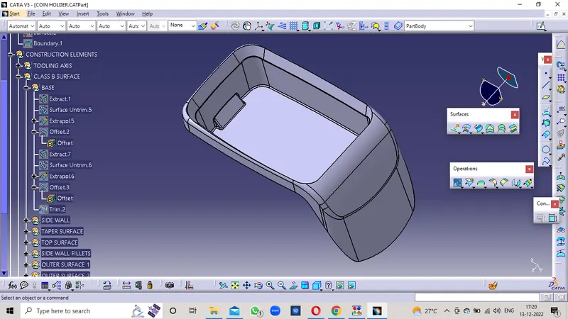
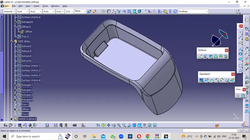
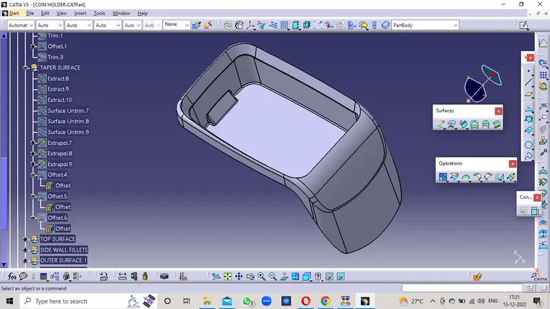
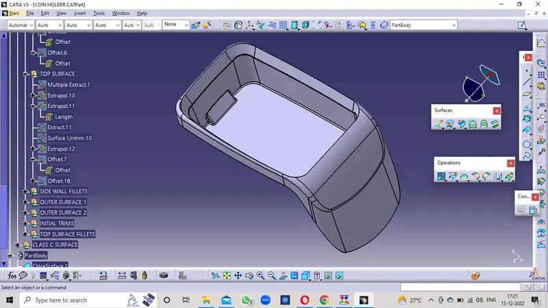
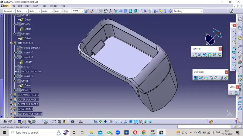
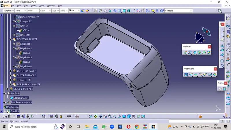
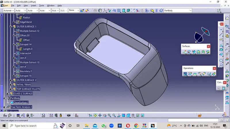
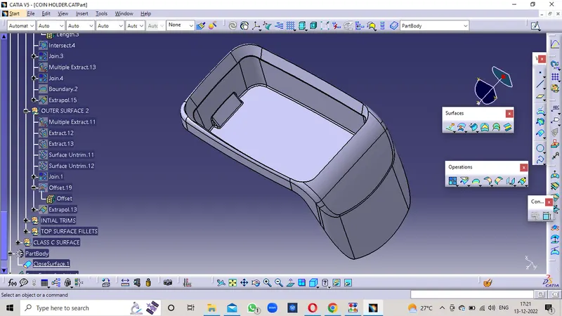
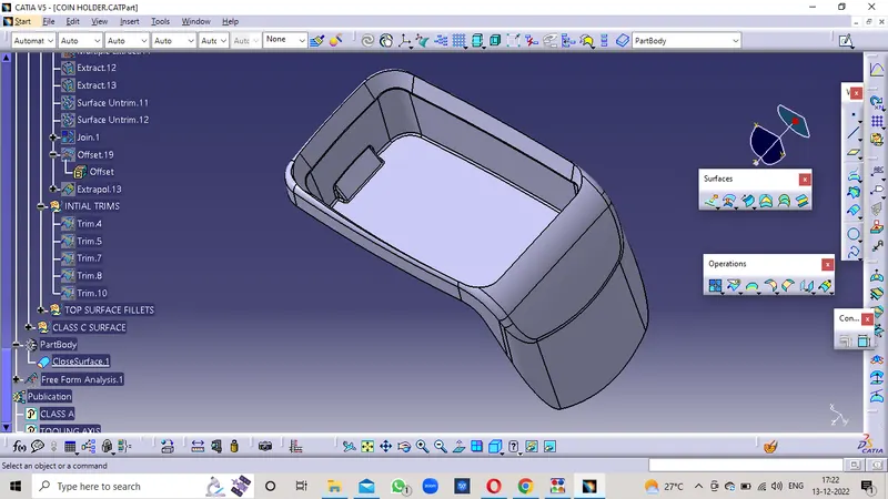
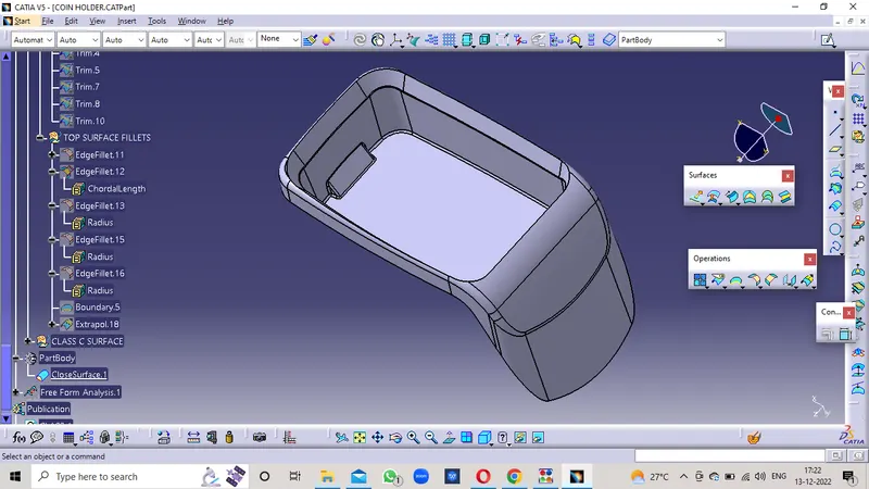
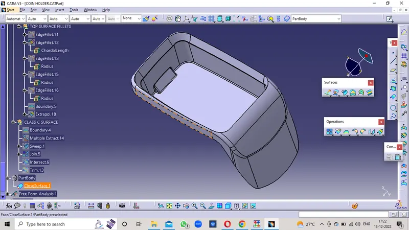
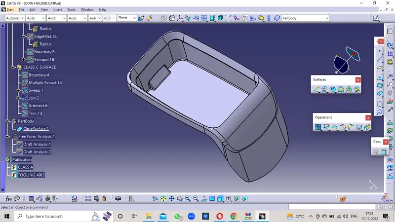
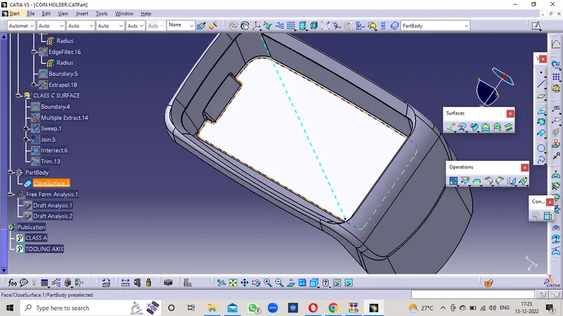
Here Attached the Tree Structure of Methods followed.
TREE STRUCTURE
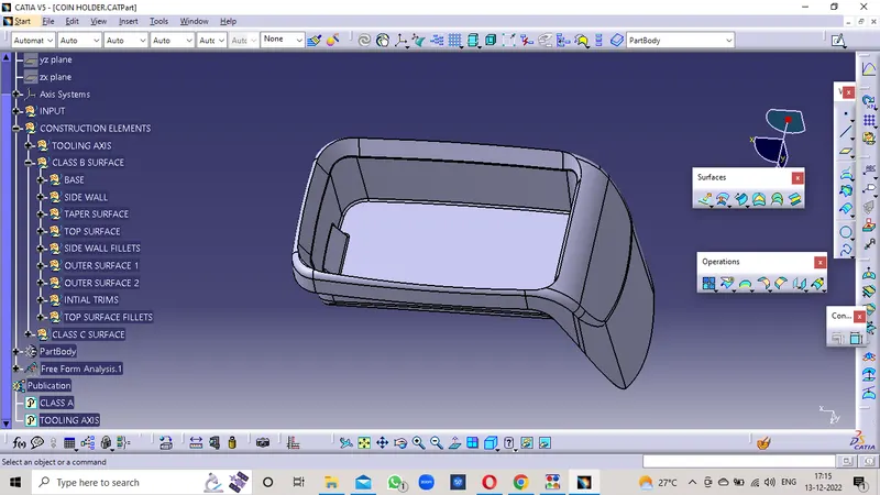
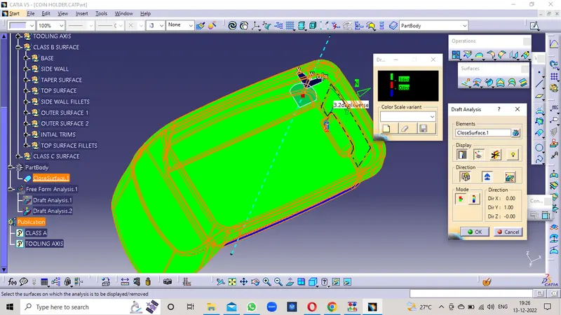
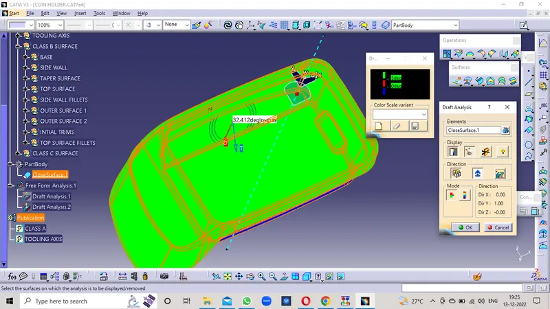
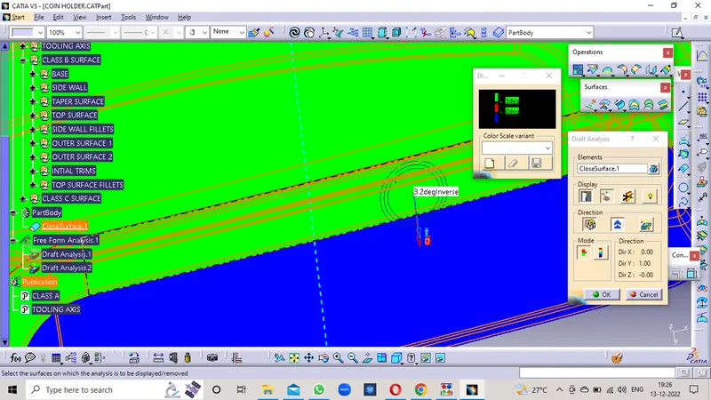
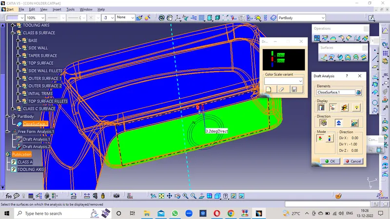
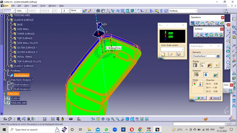
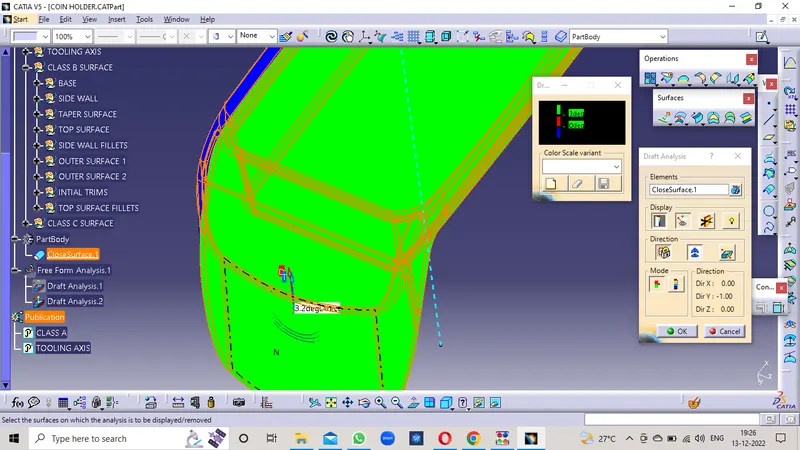
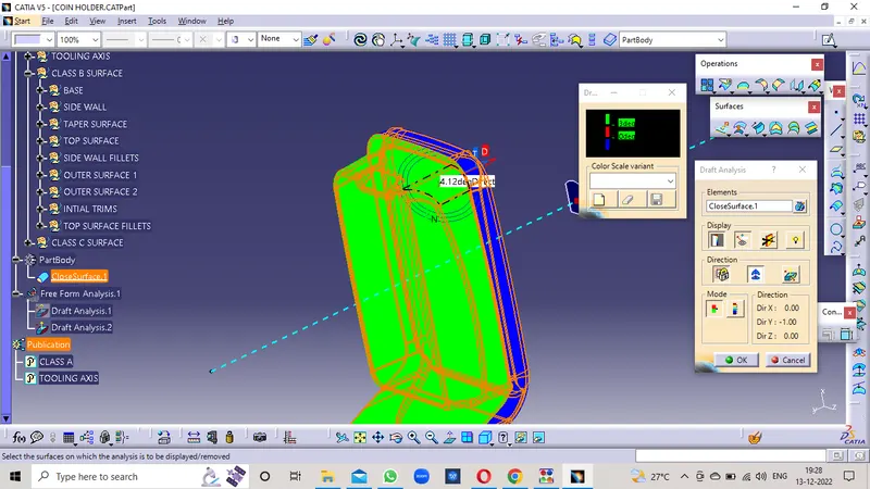
10. DRAFT ANALYSIS:
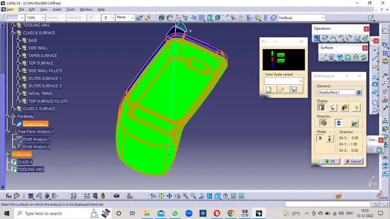
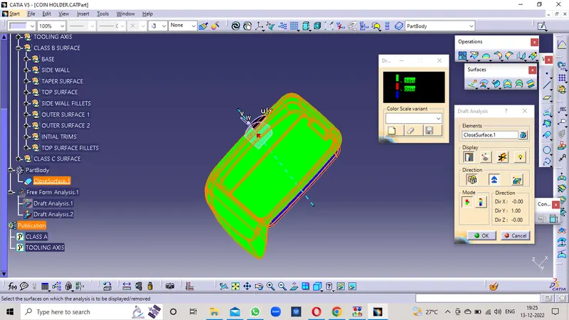
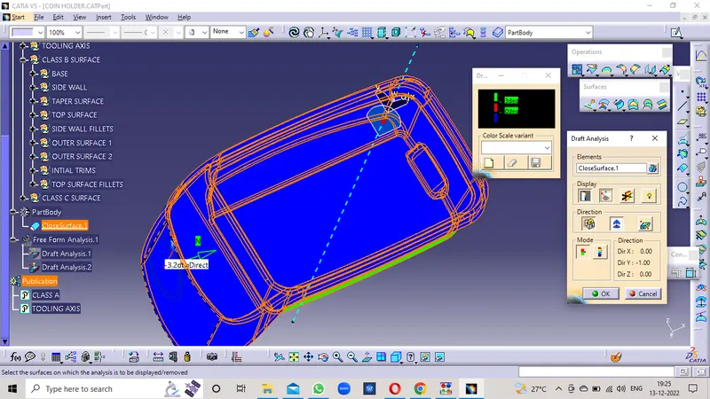
- Select the Draft Analysis to the ClOSED SURFACE.
- Select the Axis and place the Axis line along the Tooling Axis direction.
- Select the Draft angle degree as 3Deg minimum.
- Selected the Surface and found in Green Colour in all the surface area in the Draft Direction.
- Checked the inversion of Drafting to the Core side and Cavity side.
- Cross checked the angle of draft at all surfaces and found that is more than 3 deg.
Conclusion:
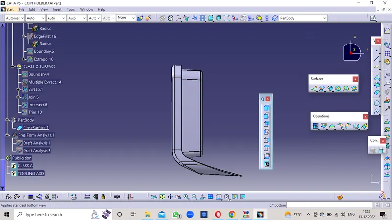
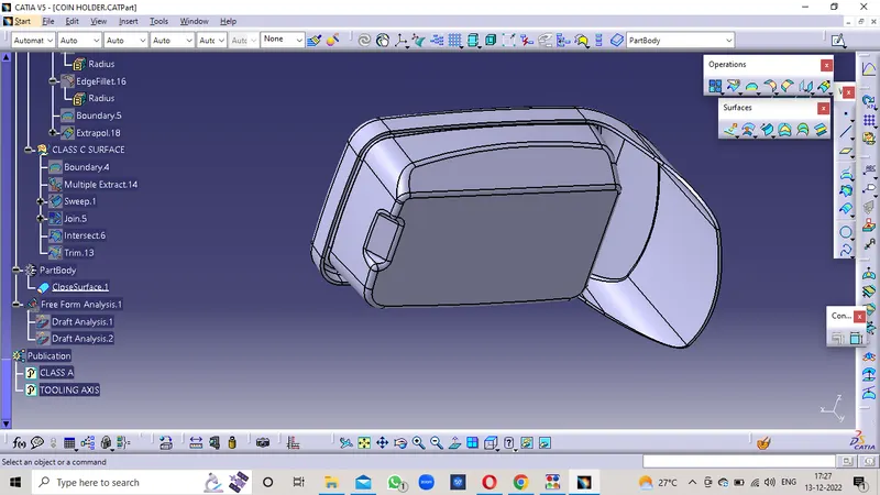
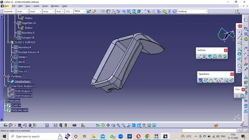
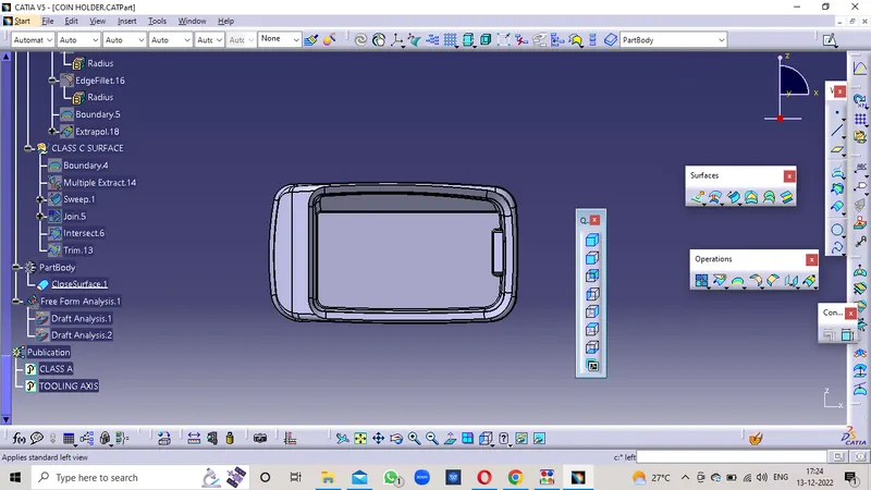
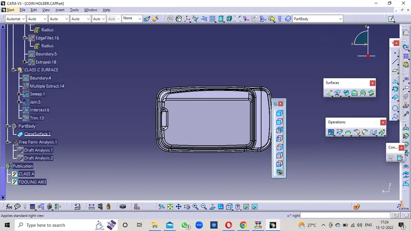
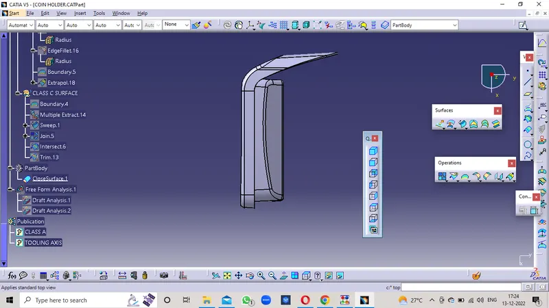
This is the method I followed and Here I attached the Different views of the Created Part Body.
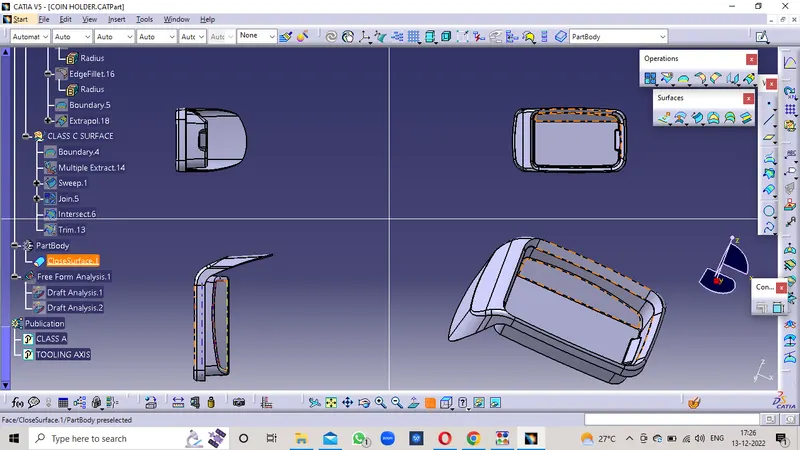
ISOMETRIC VIEW
FRONT VIEW
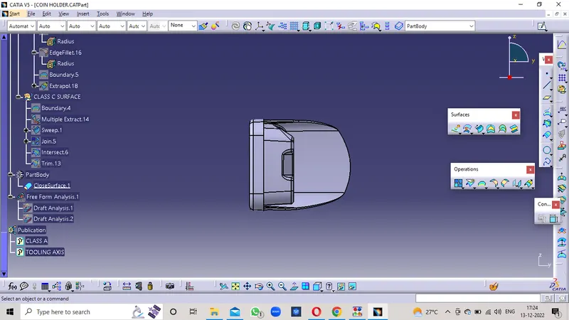
BACK VIEW
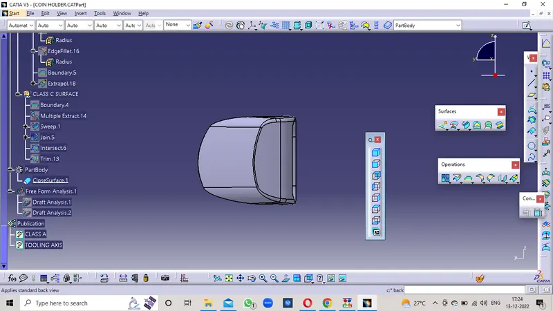
LEFT VIEW
RIGHT VIEW
TOP VIEW
BOTTOM VIEW