Week 8 - Challenge 6 - Core & Cavity Design
OBJECTIVE:
Create the Core and cavity blocks for the Switch Bezel designed in the earlier challenge.
STEPS FOLLOWED:
- Tooling Axis Creation.
- Draft Analysis of Class A surface
- Creating Class B surface and Class C surface
- Creating a Closed body of component Switch Bezel.
- Draft analysis for Switch Bezel Component.
- Creating of Parting Surface for the Switch Bezel Component.
- Creating the Parting Line for the component.
- Creating Core Block.
- Creating Cavity Block.
COMMANDS USED EXTRUDE, EXTRAPOLATE , SPLIT, TRIM , JOIN , EXTRACT , LINE , DRAFT ANALYSIS, CLOSED BODY.
KEY TERMS:
TOOLING AXIS:
- It is the direction of Mold's Core & Cavity moves.
- The Tooling Direction is basically the direction that the mold pulls apart.
- The mold is built in two separate pieces, Cavity side & Core side.
- The Core pulls apart from the Cavity and that's the Tooling Direction.
- The Line of Direction or Axis followed is Tooling Axis.
CLASS A SURFACE:
- Class A surface means Visible surface of the Component or part.
- It is the base reference to the creation of B & C surfaces that forms the Component.
- It provides the Aesthetic Appreance to the component.
CLASS B SURFACE:
- It is the mostly the Non-Visible Surface area
- It is the behind the Class A surface .
- It helps in the Parting surface creation.
- Flashes and Missmatches are done in the Class B surface , that will not distrub the Class A surface.
CLASS C SURFACE:
- It connetcs the Class A surface and Class B surface of the component.
- It also describes the Thickness of the Component.
DRAFT ANALYSIS:
- The draft analysis technique is used to analyze whether our part model created is manufacturable or not.
- Based on the Draft condition and Tooling Axis applied, Here the part should get easily removed from the Mold (Core & Cavity).
PARTING SURFACE:
- Parting Surface simply Splits the Core and Cavity of mold
- Parting surface consists mainly on the Class B surface in order to avoid the Flashes and Mismatches on Class A surface.
PARTING LINE:
- It is the Intersection of the Parting Surface and Component.
- It is also the Junction part of Core and Cavity of Mold.
CORE BLOCK:
- It is the Projection Block and the Convex part is the component.
- It is also known as the Male Mold.
- Generally the Core Part of Mold is the Movable halve.
- It consists of the Ejector Pinns
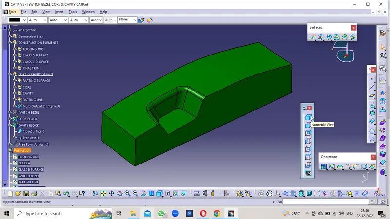
CAVITY BLOCK:
- It is the Depression Block and the Concave part is the component.
- It is also known as the Female Mold.
- Generally the Cavity Part of Mold is the Non-Movable halve.
- It consists of the Plastic Feeder like Gate and Runner system into it.
PROCEDURE:
TOOLING AXIS:
- Checked the given Class A surface contains any joints or patches on it.
- Checked the all the posibilites of Draft Tooling Axis in all directions so that the most of the surface area visible
- Confirmed that the it would be in Z direction.
- Created a Mid point in the hole Profile at the center and created a line in Z direction as the Dummy Tooling axis.
- An intersection in ZX plane along the mid point on the surface bottom and picking the lines that are coinciding with the walls.
- The Bisection of the Two lines at the centre point with suppot of Dummy Tooling Axis is Formed.
- Now in ZY plane making an intersection at the center point and Creating the line coinsiding to the wall, and the line that passes to the center point and 10Deg to the surface line.
- Bisecting the Lines and with Dummy Tooling Axis at the Center point .
- The formed Bisected Line is the Tooling Axis after only the Draft analysis is performed and minimum draft angle is 3Deg.
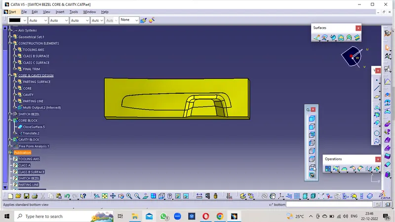
X-Direction
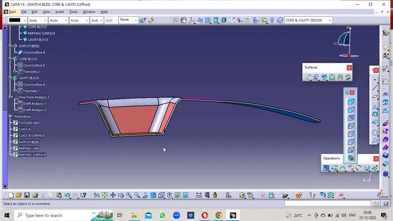
Y-Direction
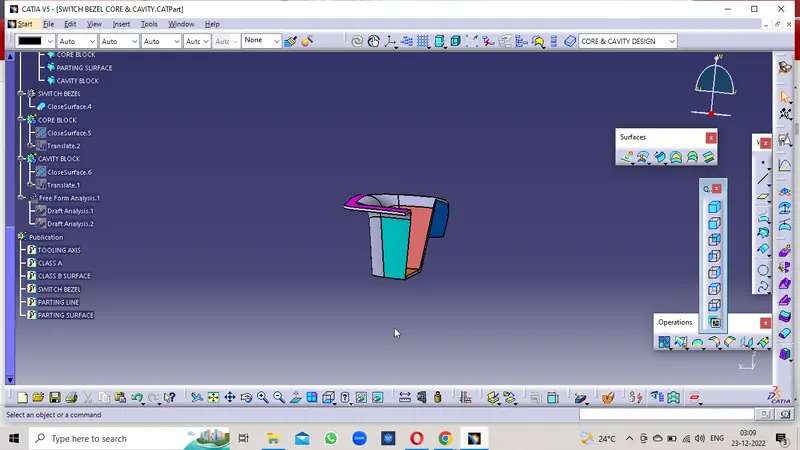
Z-Direction
In this direction most of the area is Visible and Hole also availabe at here.
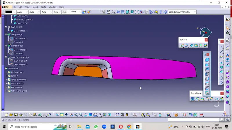
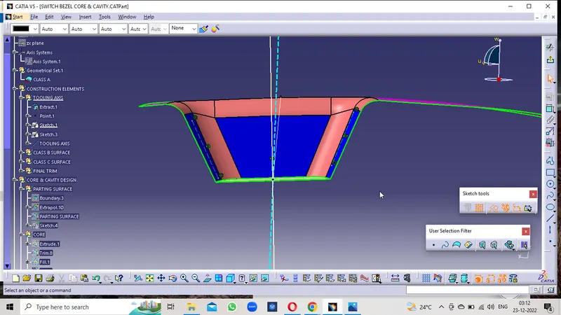
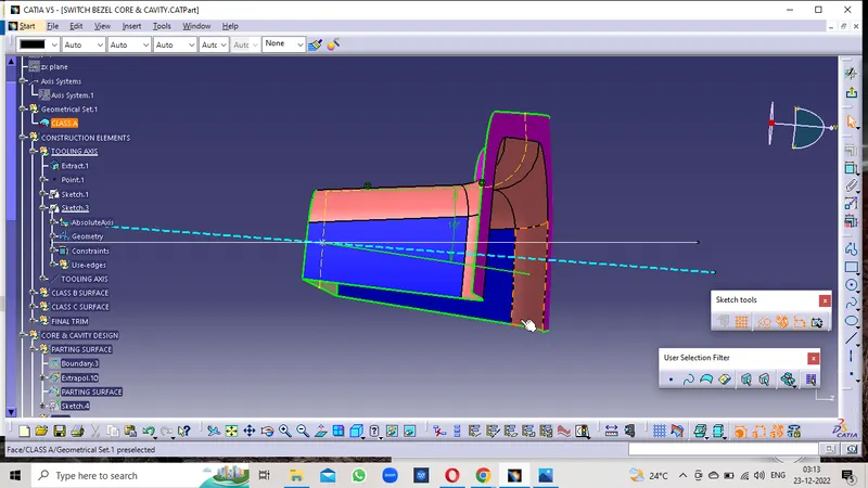
Final Tooling Axis
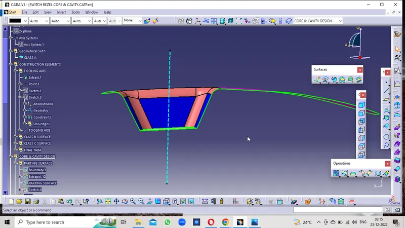
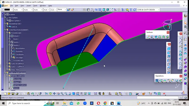
DRAFT ANALYSIS:
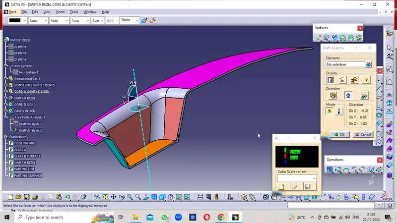
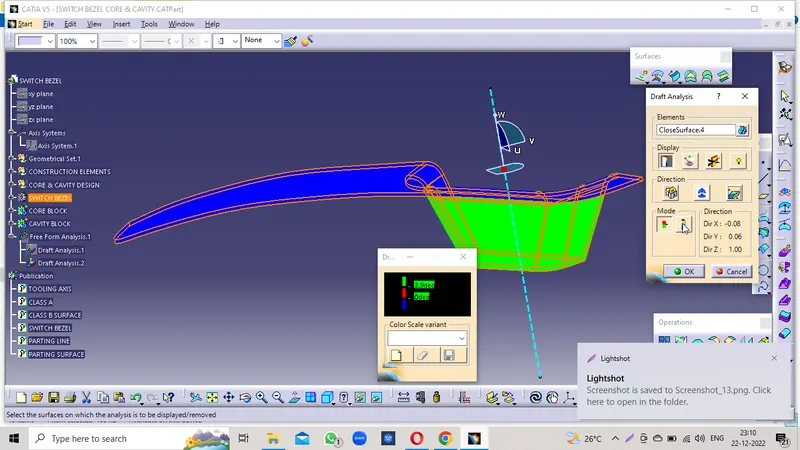
- Select into the Material Mode and Insert the Feature Draft Analysis
- Select the Compass place in the Tooling Axis Direction and activate the Compass , adjust the compass to the Tooling Axis Direction.
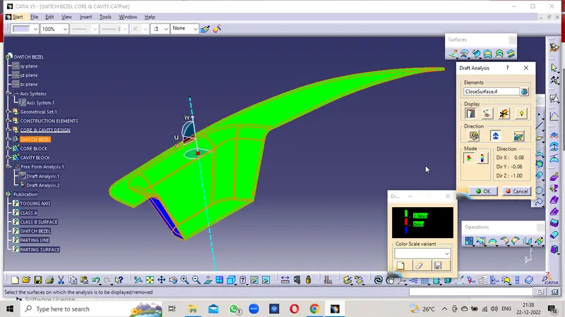
- Provide the Minimum Draft angle is 3Deg
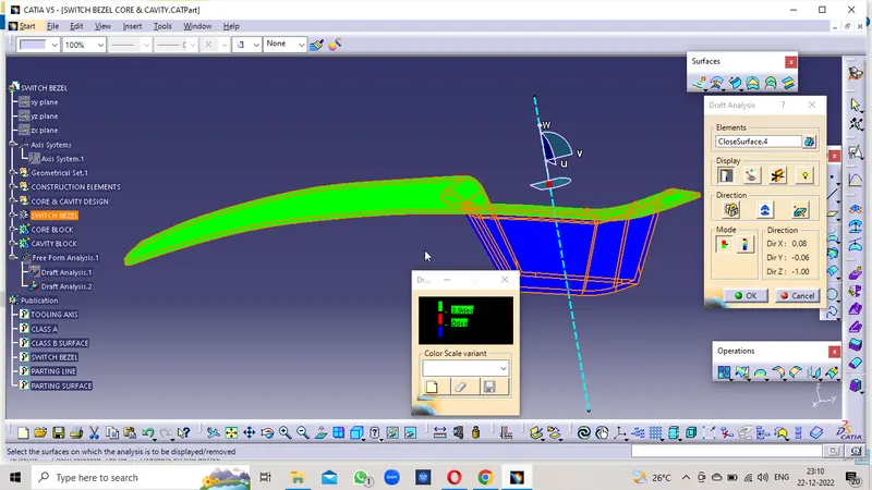
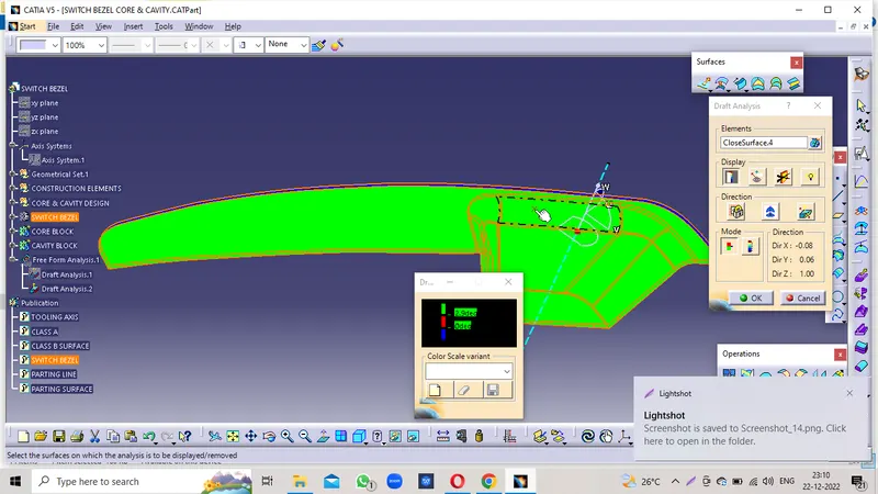
- Select the surface So that the Green Area is more than 3Deg draft angle and it is manufacturable.
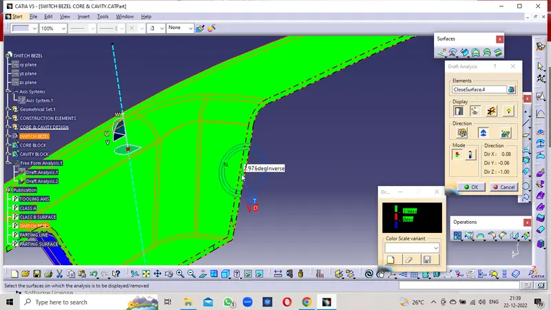
- Select the Draft analysis inverse side so that confirms it is also cleares the another side for the same 3Deg Draft angle.
- Here at a point at the Class C surface the Draft angle is 2.967Deg that approx value is almost to 3Deg .
PARTING SURFACE:
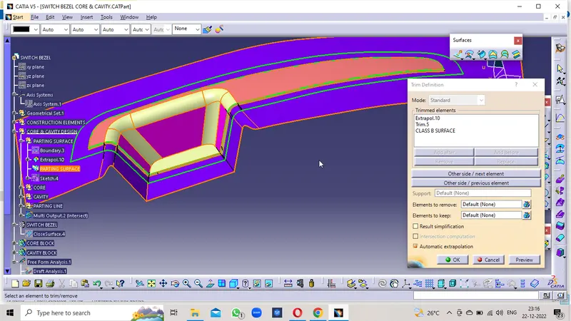
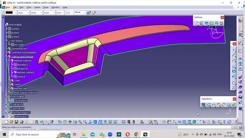
- The joined Class A & C surface is taken from the Component Created and trimed with the Extapolated Class B surface.
- The Created surface is the Parting Surface along with the Component area.
- If it is Splited with the Parting Line , Then it is the Parting Surface.
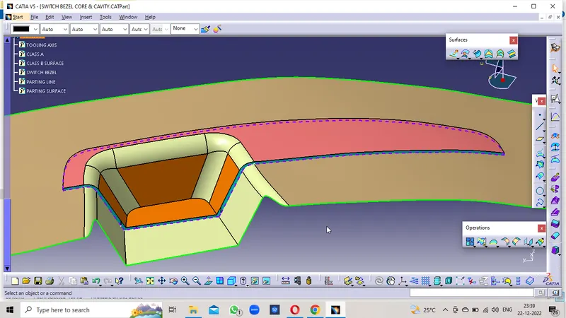
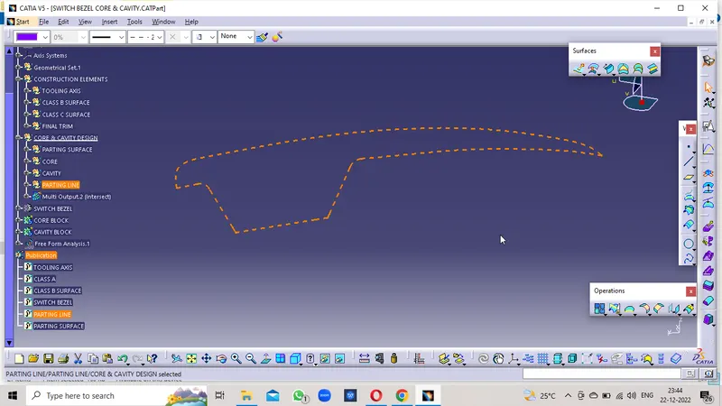
PARTING LINE:
- It is the intersection of the joined Class A & C surface with the Class B surface
CORE BLOCK DESIGN
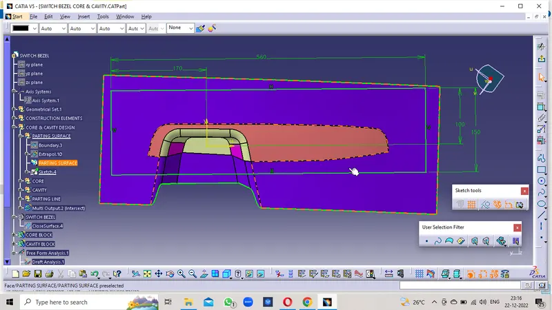
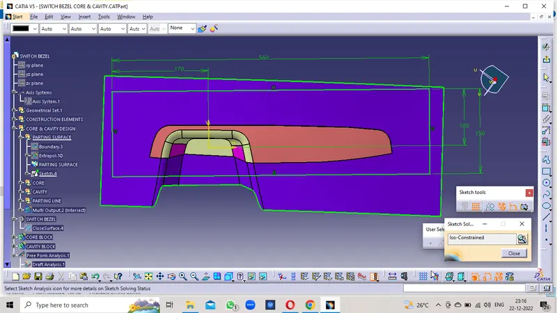
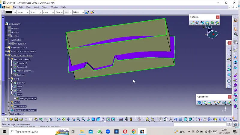
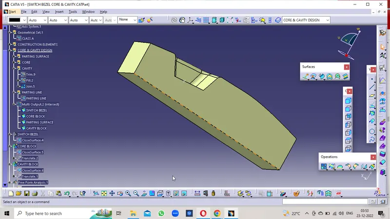
- Create a rectangular box inside the Parting Surface in the base plane Direction(ZX).
- Extrude the Rectangle in the Tooling Axis Direction in both sides.
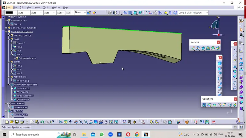
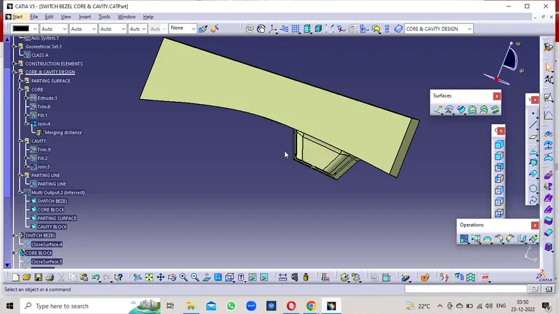
- Trim the Parting Surface with the Extruded rectangle in the Projection side.
- The Profile is created to the outer side.
- Fill the top surface with help of Fill command and join it with Join Command.
- Now make it a Closed Body in the Part Body and Rename it.
CAVITY BLOCK DESIGN
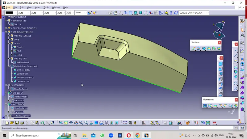
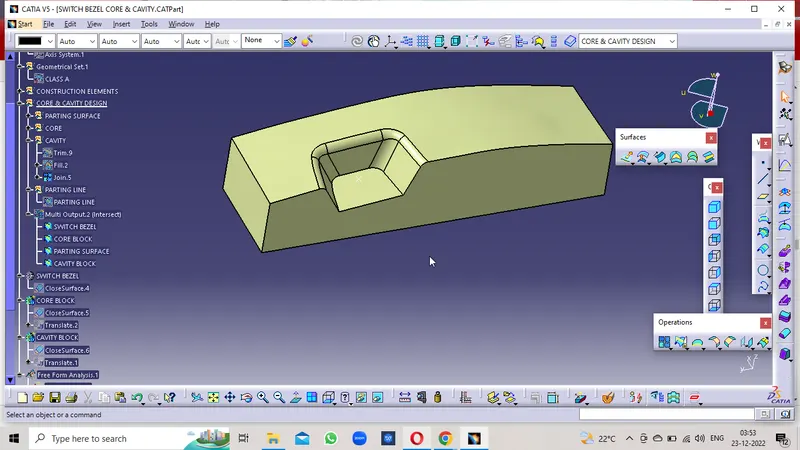
- Use the same Extruded Rectangular Box and Parting Surface
- Trim the Parting Surface with the Extruded rectangle in the Depression side.
- The Profile is created to the Inner side.
- Fill the top surface with help of Fill command and join it with Join Command.
- Now make it a Closed Body in the Part Body and Rename it.
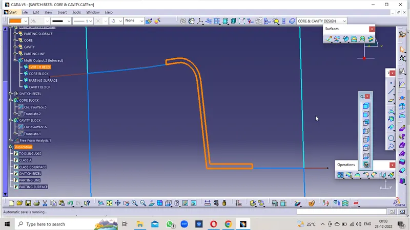
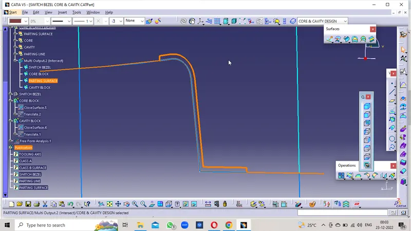
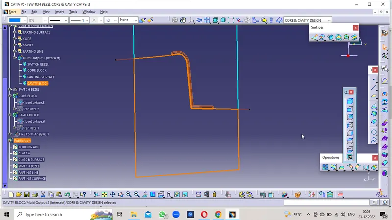
INTERSECTION PROFILE
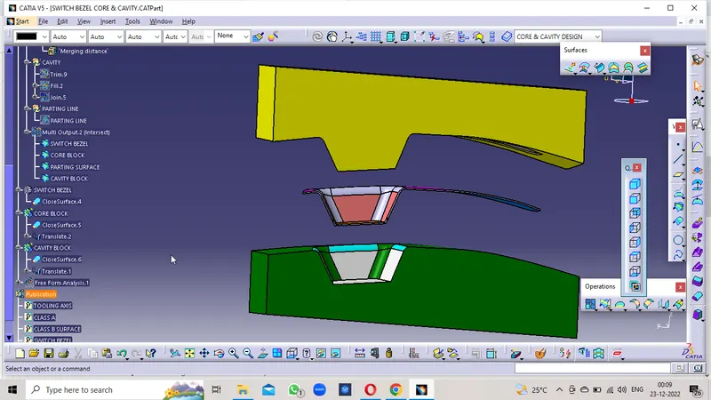
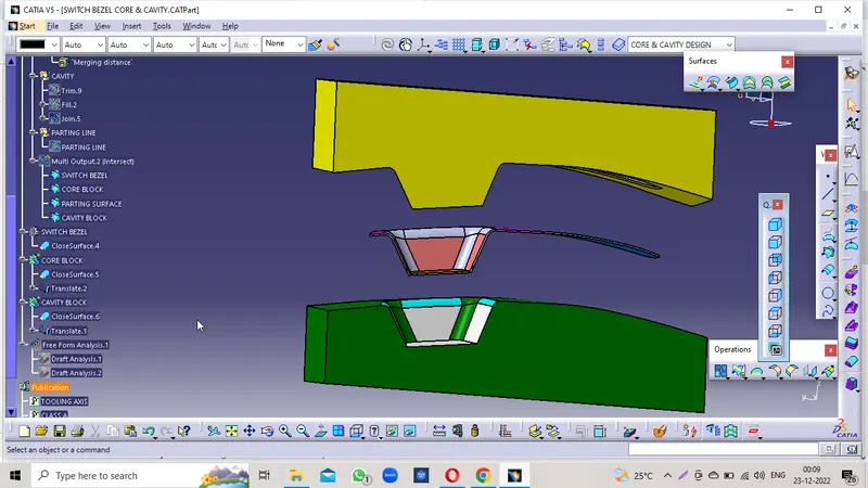
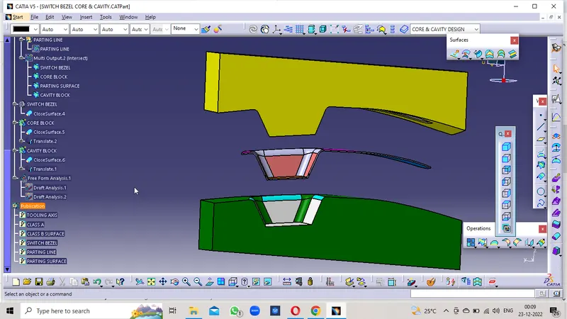
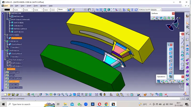
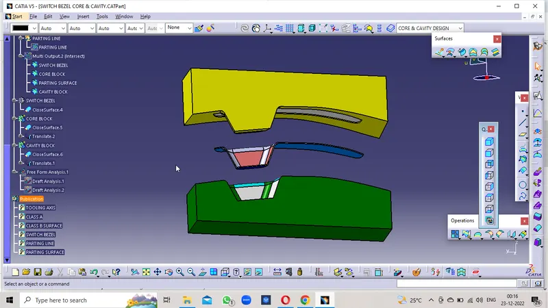
- Now make an Intersection in the Tooling Axis, for the Core Block, Cavity Block, Parting Surface and Comonent
- The results are attached below
Switch Bezel Component
Core Block
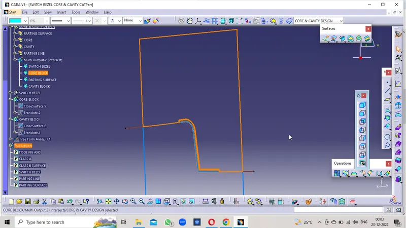
Parting Surface Line
Cavity Block
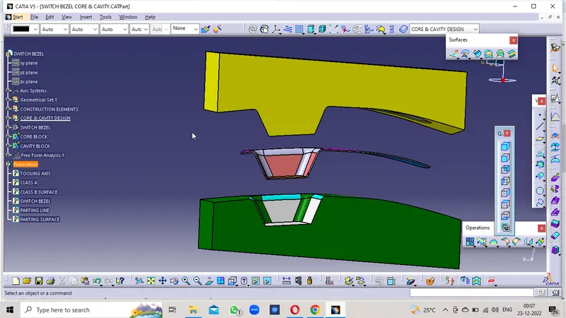
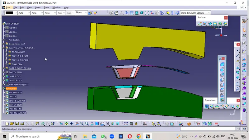
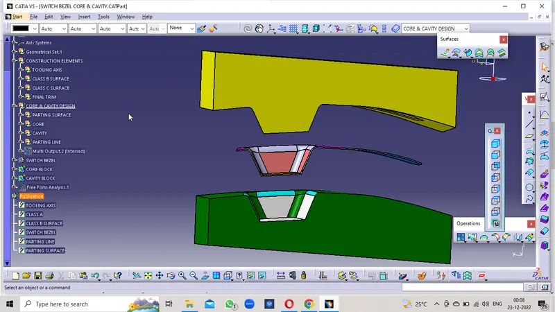
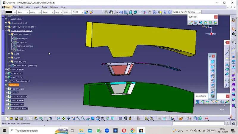
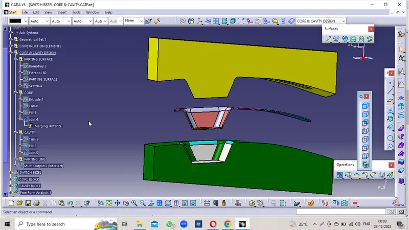
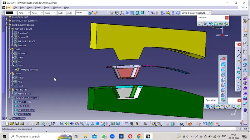
TREE STRUCTURE:
This Describes the Method that I followed to make the Core and Cavity of Switch Bezel Component.
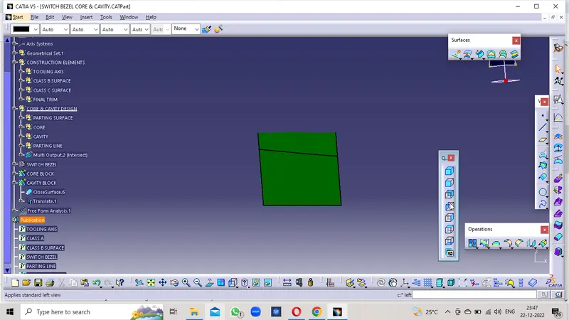
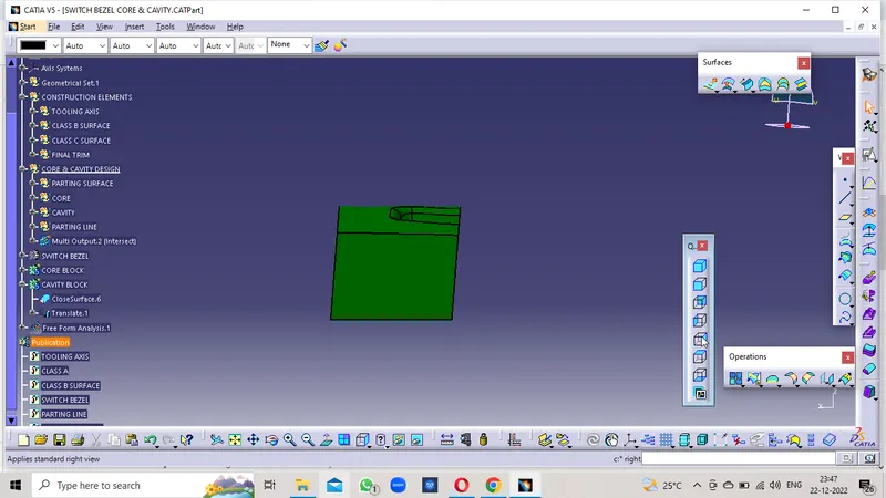
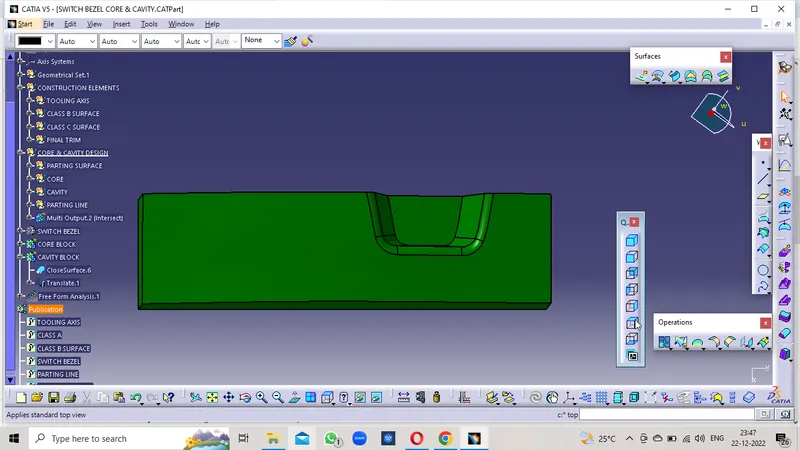
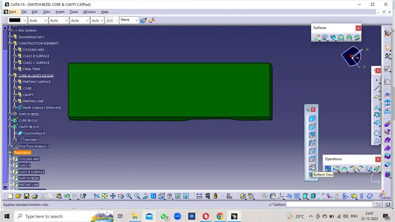
CAVITY BLOCK:
ISOMETRIC VIEW
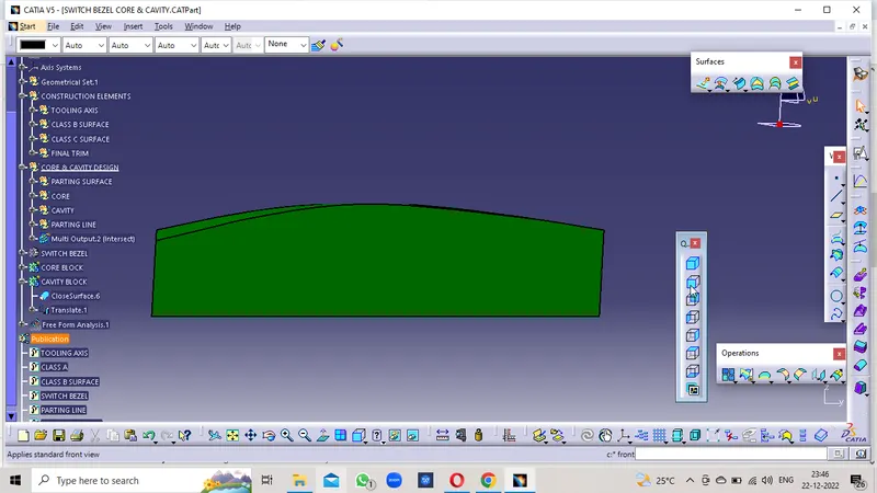
FRONT VIEW
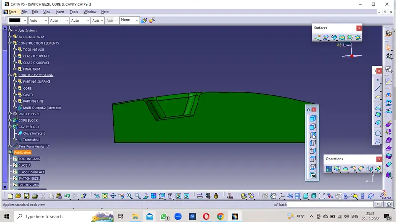
BACK VIEW
LEFT VIEW
RIGHT VIEW
TOP VIEW
BACK VIEW
CORE BLOCK:
ISOMETRIC VIEW
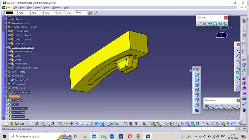
FRONT VIEW
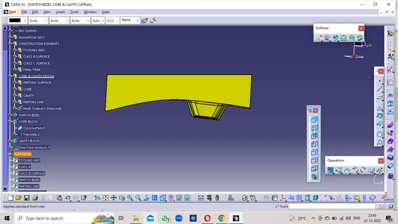
BACK VIEW
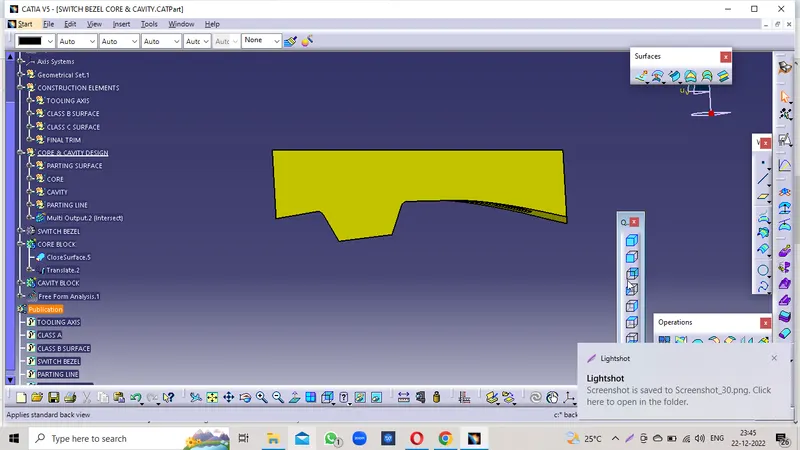
LEFT VIEW
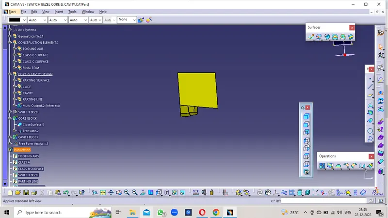
RIGHT VIEW
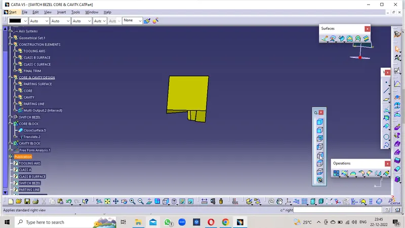
TOP VIEW
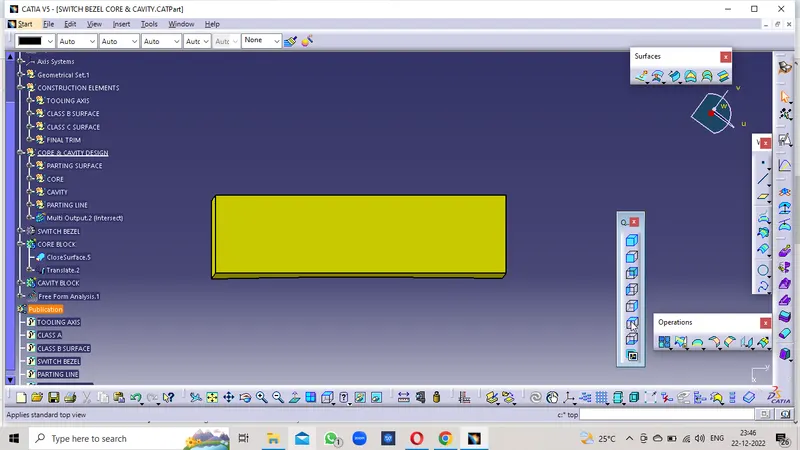
BACK VIEW