Week 8 - Challenge 1 - Base Bracket Design
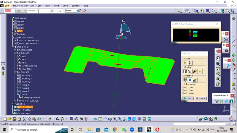
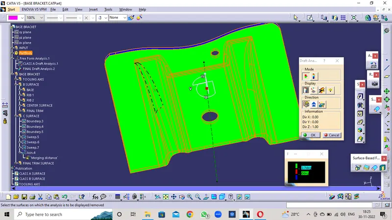
- done the draft analysis for the given class A surfase and found ok
- By observing the given class A surfase model and assuming all the posibilites of the Drafting and tooling axis direction .
- Then found out that the Z axis is the most suitable as the Tooling axis.
- there are 2 holes in the class A surface and in the small hole there are no parllel surface that to check and all the surface is perpendicular to it
- in the larger hole there are 4 parlell surfaces facing in the two different directions so need to check the tooling direction will be correct or not
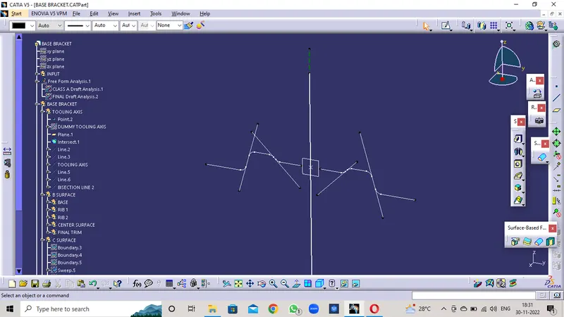
- create a point at the center of the hole and create a dummy tooling axis in the Z direction along the point.
- by creating an intersection of the surface at the center of the hole and checking along with the dummy tooling axis.
- creating the lines that are parllel directions to the dummy tooling axis and finding the bisecting line of it along the point in the z direction for all the parllel lines and fount that the assumed dummy tooling axis is the right choice.
- picking any one of the line among the dummy tooling axis or bisecting lines because all the three are the same ones and coincident ones. I am choosing and naming the 1st bisection line as the Tooling axis line.
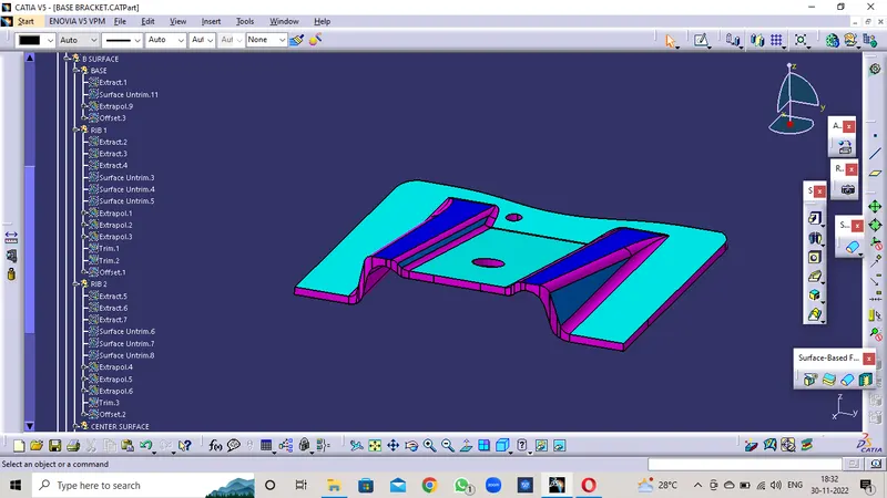
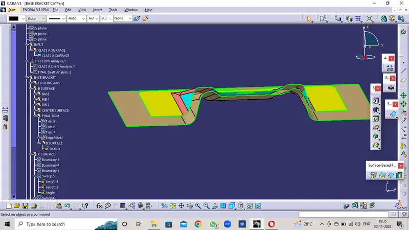
- picking all the surfaces and avoiding the fillets and extracting them to create a B surface.
- all the surfaces should be untrimmed and extrapoled to the required distance to form the new surface , here we have the 2 ribs and 2 base platforms
- making all the surfaces extrapoled and trimmed it to form the same profile as the class a surface without fillets on the edges.
- making the offsets of the surfaces that are created upto the thickness of the component , here the thickness is 2.5mm , so the offset value is 2.5mm in the bottom direction( along the component direction)
- then all the offseted surfaces are trimmed to get the same structure as the class A surface.
- finding the fillet value of the class A surface and ares that are filleted. To find the Proper fillet radius we use the intersection line as the reference . The fillet radius is found to be 3.0mm on average on the surfaces.
- fillet values are given the offset planes so at the ares filleted at the class A surface . we have to add or subtract the thickness value to the fillet radius in order to maintain the shape and thickness everywhere uniformly between the class A and Class B surface.
- Here the fillet radius is the outer one so we have to add the thickness to it so the value is 3.0mm+2.5mm=5.5mm
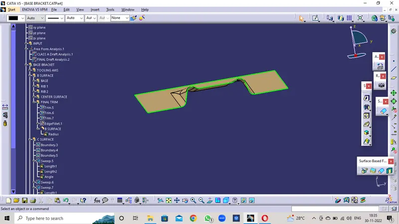
- then the output got is the class B surface.
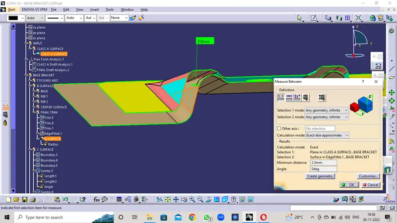
- check and measure the distance between the class A surface and Class B surace that is 2.5mm that is the thickness of the pat body.
- creating the all the possible boundary of the class A surface, here we found 3 boundaries 1 full boundary and 2 holes.
- creating the Class C surface by using the sweep comand and along the direction of the draft option and direction as the tooling axis and the draft angle is 3deg, and the draft direction is outer side of the component so that it clears the draft analysis an the component will be easily ejected from it.
- repeted for the both holes as same and make sure that the all intersecting or we need to extend the surfaces.
- then joining the class A surface and the created class C surfaces and check that there is no gaps and boundaries formed above the surface
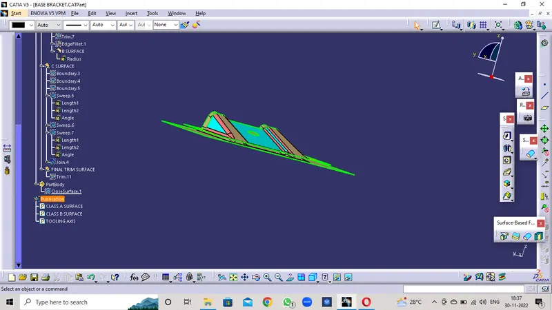
- then trim the joined surface with the class B surface and form the component a closed one
- check the boundary option so that the there is no open curves or boundaries formed on it.
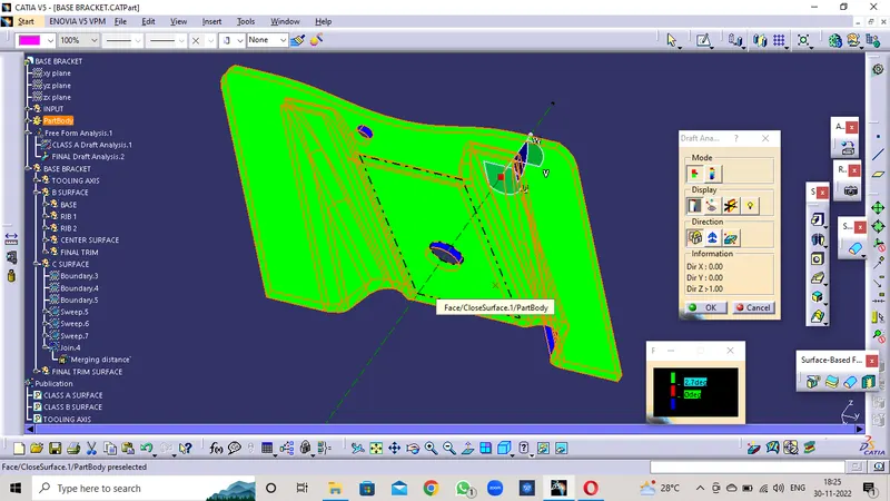
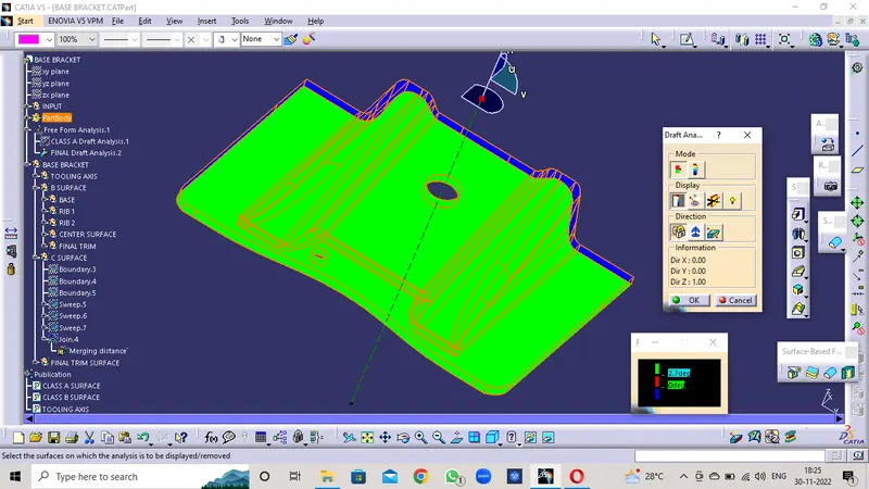
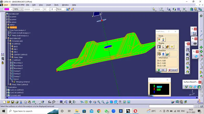
- Draft analysis is carried to the closed surface and found ok
- some of the areas are getting the 2.78 deg on the class c surface and found ok and the class b surface is also ok.
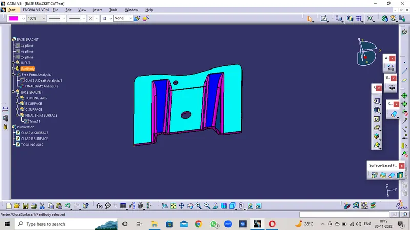
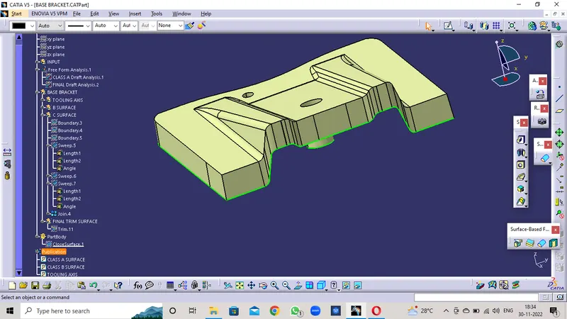
- making the closed surface as the part body
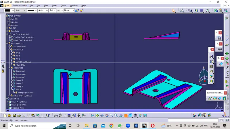
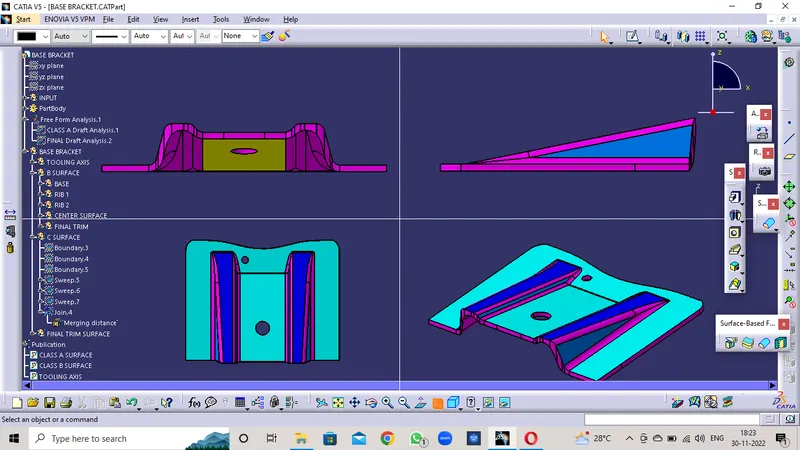
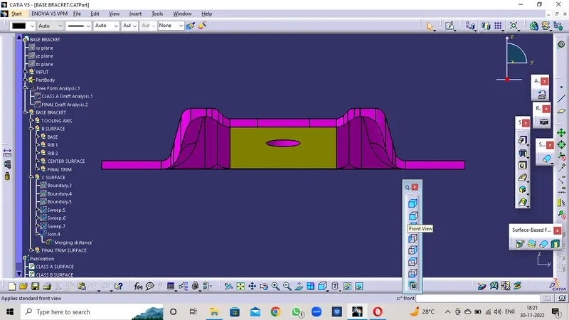
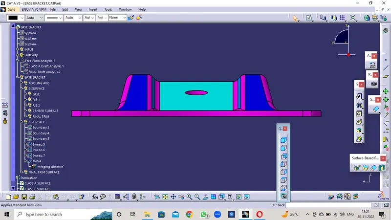
- the images of the diffrent views are subbmitted below alond with the draft analysis and tree structure also
DRAFT ANALYSIS OF CLASS A
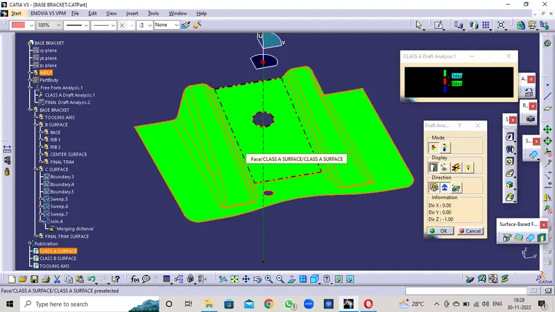
DRAFT ANALYSIS OF CLOSED BODY
CREATING TOOLING AXIS BY BYSECTING OF PARLLEL LINES
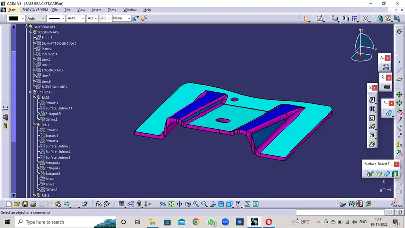
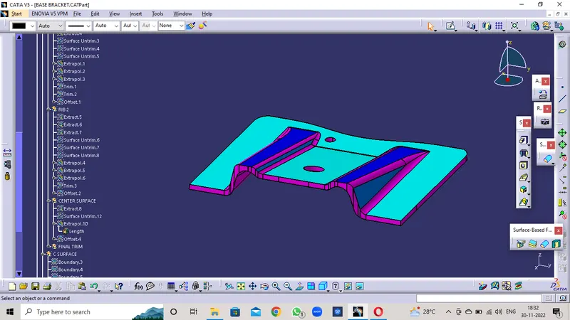
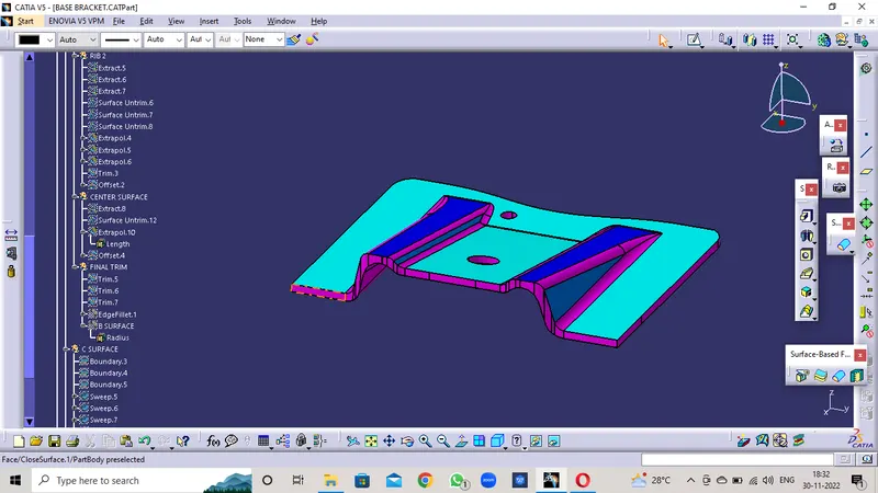
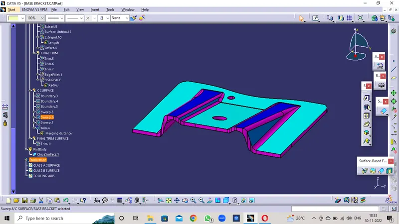
TREE STRUCTURE
SWEEP SURFACE COMAND
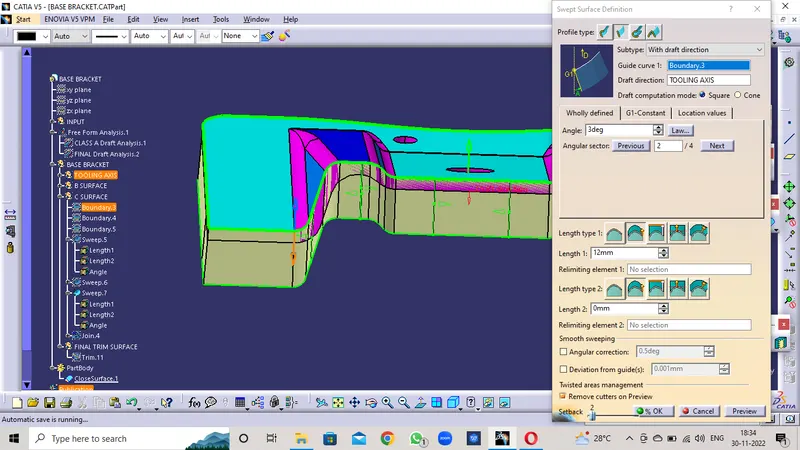
CLASS C SURFACE ALONG WITH CLASS A
CLASS B SURFACE
CLASS A AND CLASS B SURFACE
FRONT VIEW
BACK VIEW
LEFT SIDE VIEW
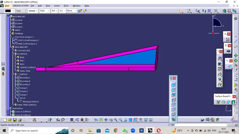
RIGHT SIDE VIEW
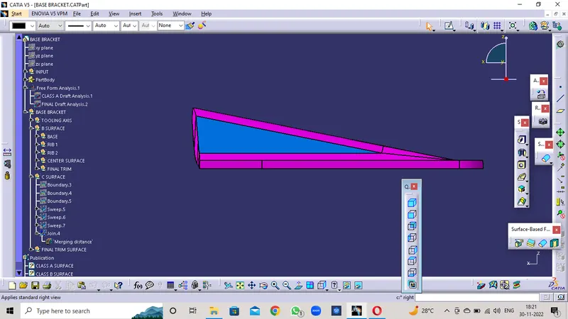
TOP VIEW
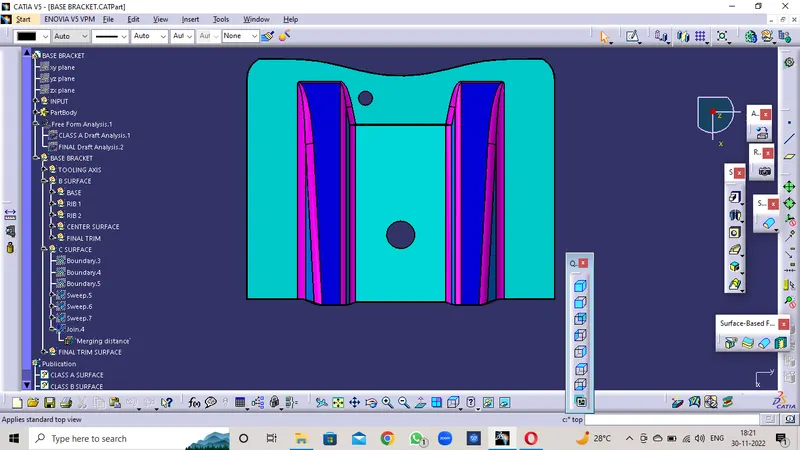
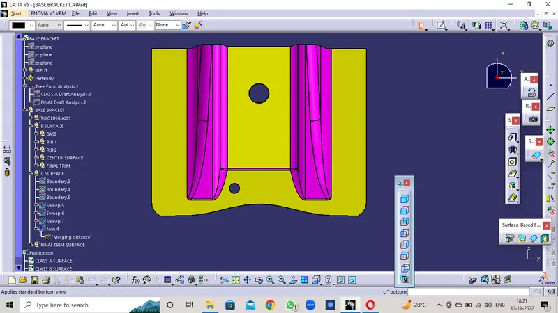
BOTTOM VIEW