Week 9 - Project - A pillar Design with Master Section
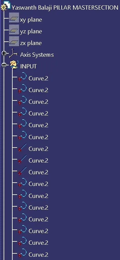
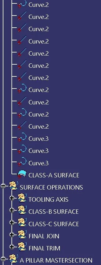
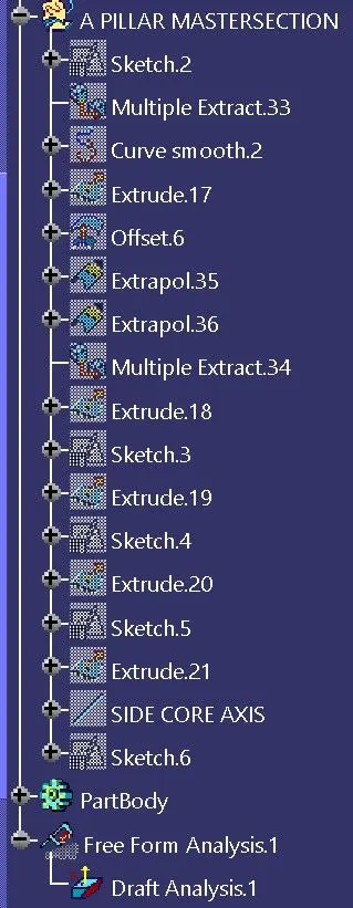
STRUCTURE TREE
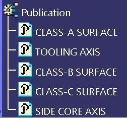
ISO-CONSTRAINED SKETCH
SKETCH-2
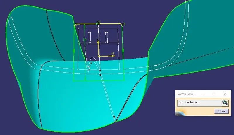
SKETCH-3

SKETCH-4
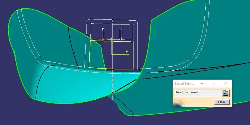
SKETCH-5
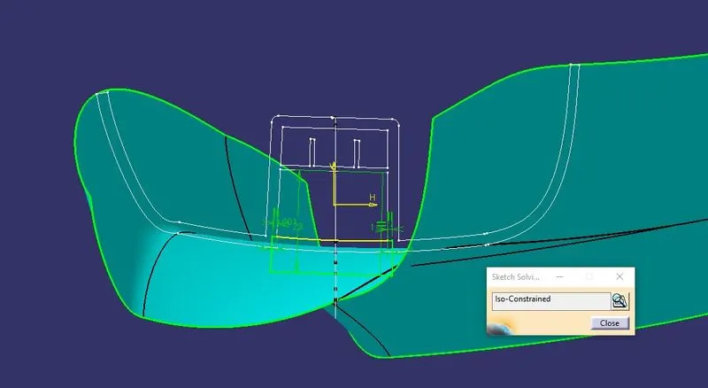
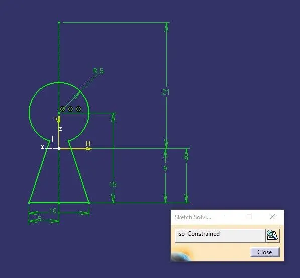
SKETCH-6
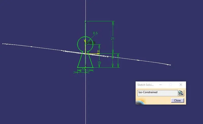
REPORT
- The current challenge "A PILLAR MASTERSECTION" is done using the "extraction method" from the provided input with minor corrections in the sketches and boolean operations.
INPUT
- From the given input,there is class-A surface and the pillar mastersection in the form of curves and lines.
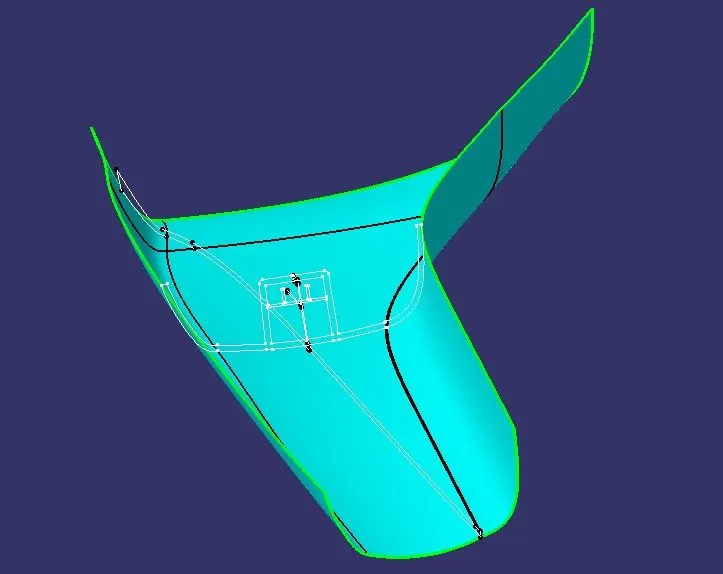
TOOLING AXIS
- EXTRACT the line from the given input curves.
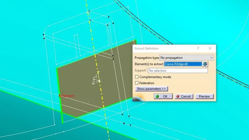
- EXTRUDE the profile(Extract) using the direction from the curves to form a surface upto required length.
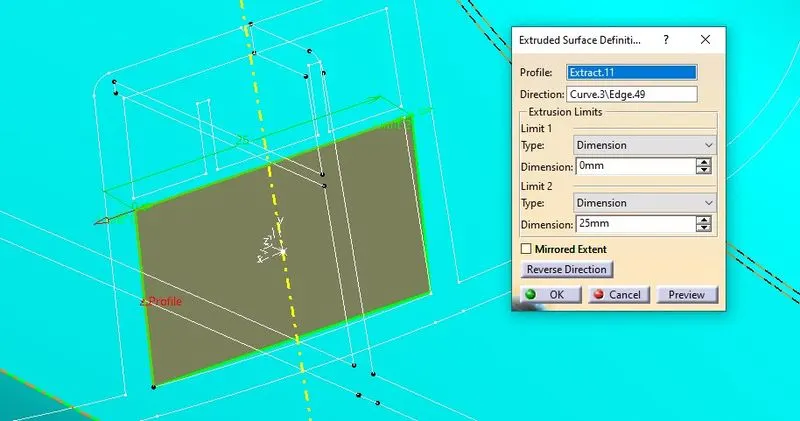
- Create a POINT at the centre of the surface as the base for the AXIS system as the direction is different from the default axis system and the axis's using the input curves.
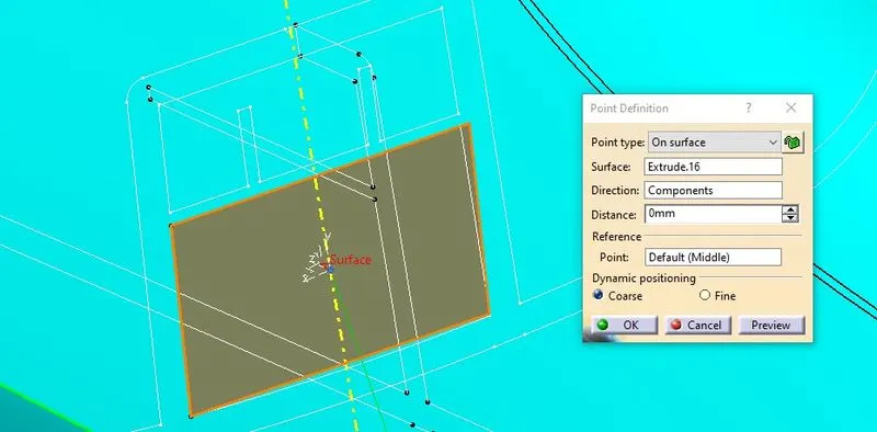
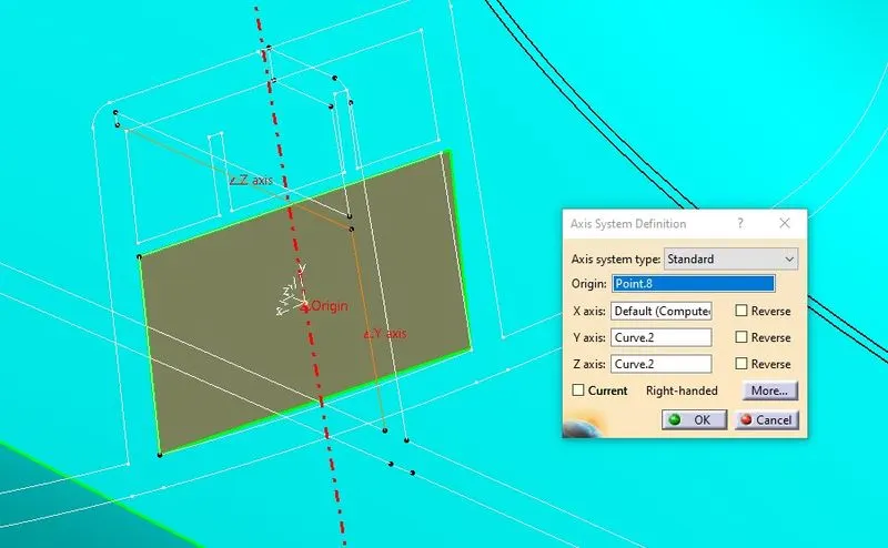
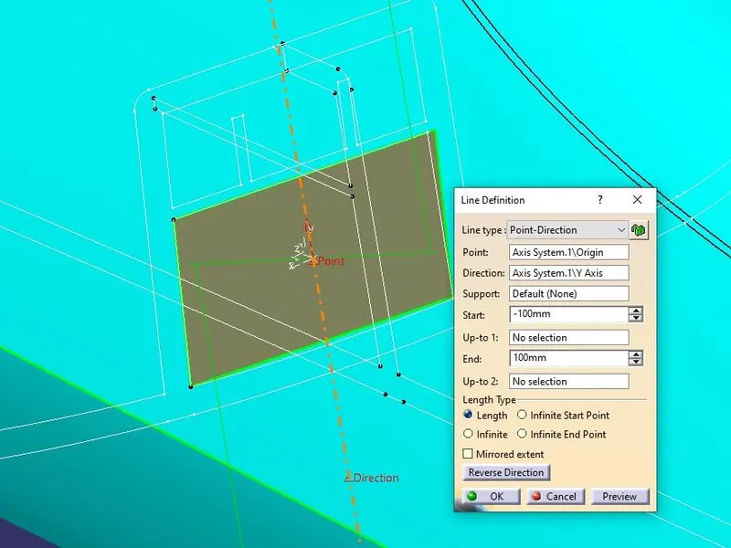
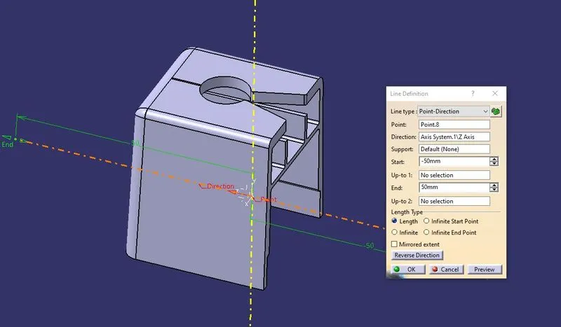
- Using the Point and the new Aixs system,create a line in the new Y-axis with the required length using the "Point-Direction" method.This newly formed line is now the TOOLING AXIS throught out the component.
CLASS-B
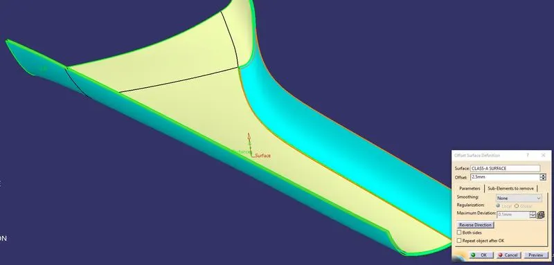
- Class-B is created using the Offset command of 2.5mm opposite to the surface to provide thickness to the component.
- If there are any gaps in the newly formed Offset surface,fill them using the "multi-section" option only and Fill option should not be used as it is not the Industrial Standard.
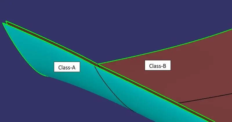
CLASS-C
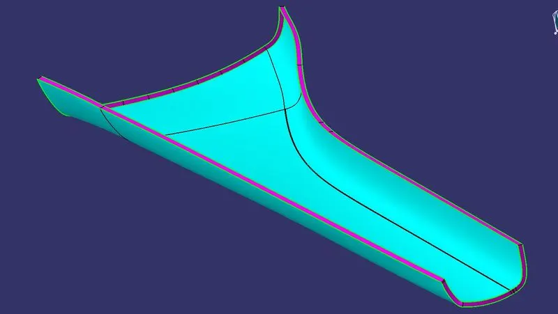
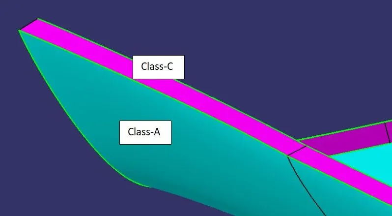
- Class-C surface can be formed by using the SWEEP operation using the Tooling Axis and Surface as the Support from the profile which is taken using the MULTIPLE EXTRACTION or EXTRACT in the required areas to form a closed Surface Component.
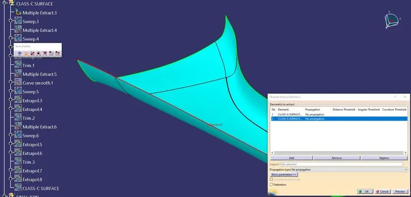
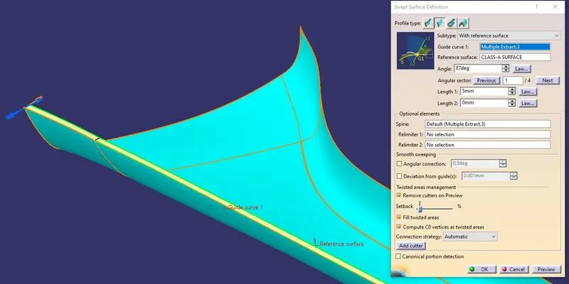
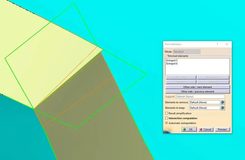
- If there areany gaps found during this phase,they can be filled using EXTRAPOLATE and TRIM commands to form a single surface component as CLASS-C.
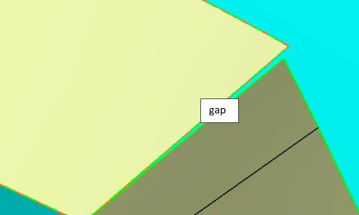
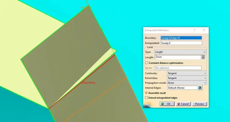
- You can use the Trim command here,but at the bottom there is no intersection,so use Extrapolate on the other Edge of the surface and Trim them to get a clean and neat intersection and the two surfaces merged together.
- The Class-C you aquire at the end is shown below.
FINAL SURFACE COMPONENT
- FINAL JOIN is the operation performed when class-A and C are joined together using the JOIN command.
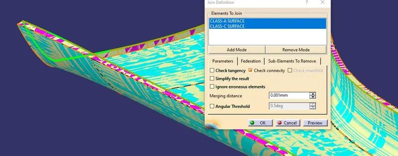
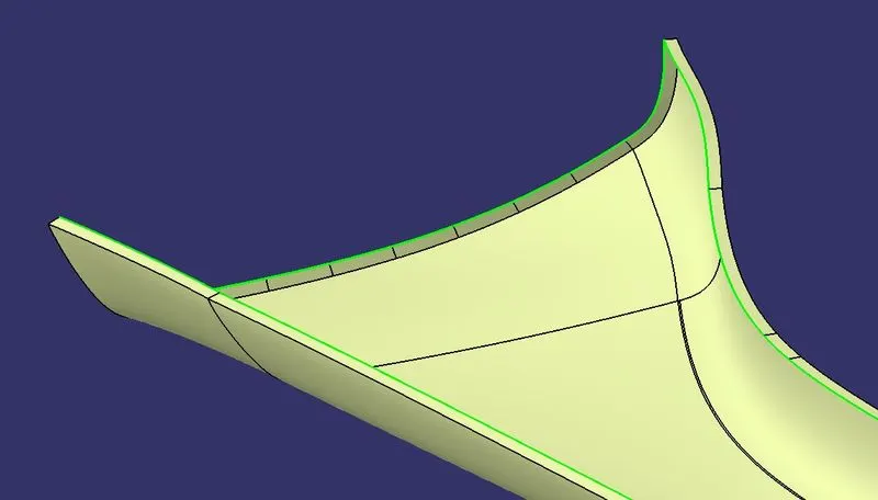
- FINAL TRIM is the operation performed when FINAL JOIN and class-B are trimmed to get a closed surface component.Apply EXTRAPOLATION on the edges of these two surfaces to get a perfect intersection between the surfaces if needed.
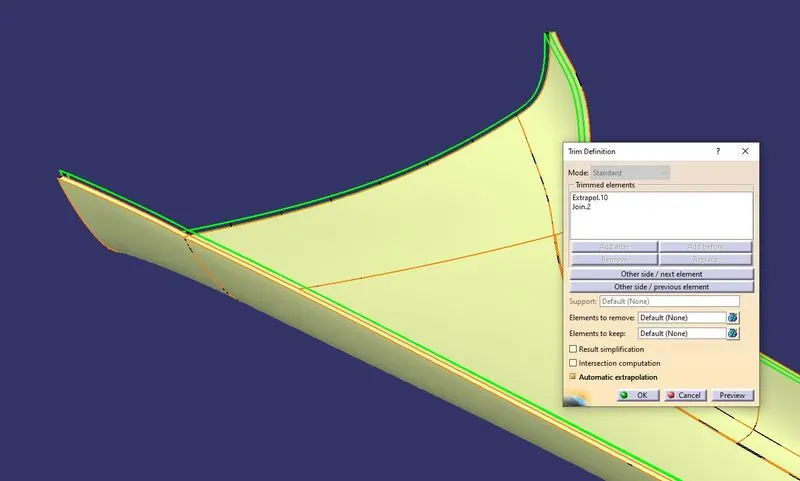
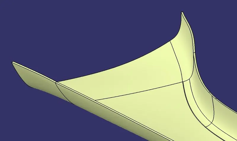
- In the Part Body section,right-click on it to define it and select Closed Surface to form a solid component of the FINAL TRIM.
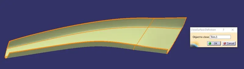
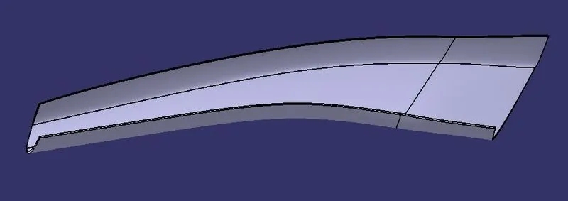
- FRONT VIEW
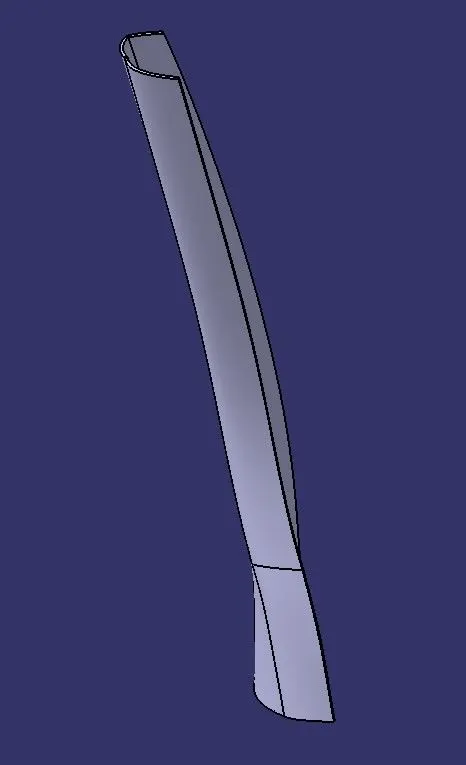
- RIGHT-SIDE VIEW
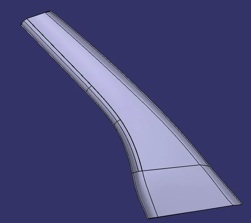
- TOP VIEW
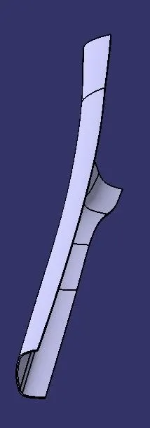
A PILLAR MASTERSECTION
- The Pillar Mastersection design is based on the standard Dog House design and there are certain standards in creating it.
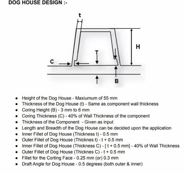
- Since we have been provided with guide curves of how th Pillar Mastersection,there will be some changes in the dimensions.
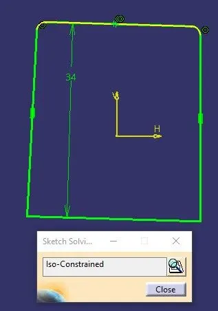
- The Pillar Mastersection was created from taking an Extract from the provided input curves and add some minor changes in the sketches.Let's see how it is made step-by-step.
- Create an Extrude in the Z-axis direction using the sketch which is done using Projection 3D element after implementing required changes in Shape Design.
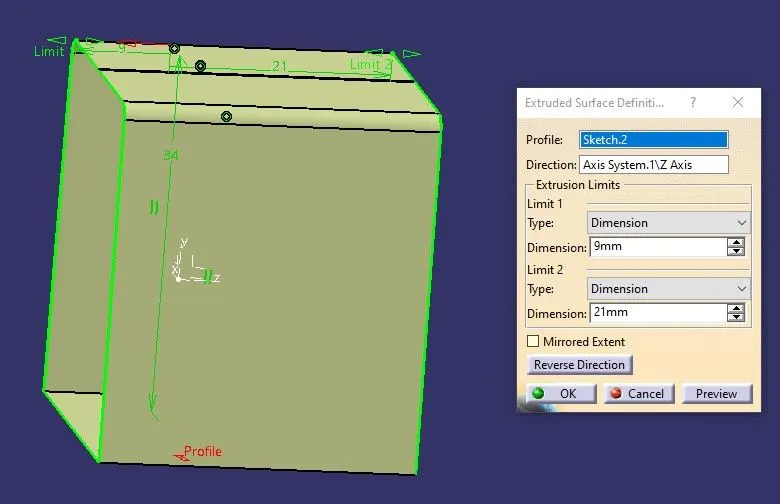
- Now using this Extrude we create solid body using the Closed Surface command by inserting a Body and define it as "A PLLAR MASTERSECTION" for further reference.
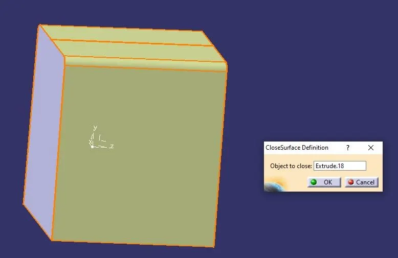
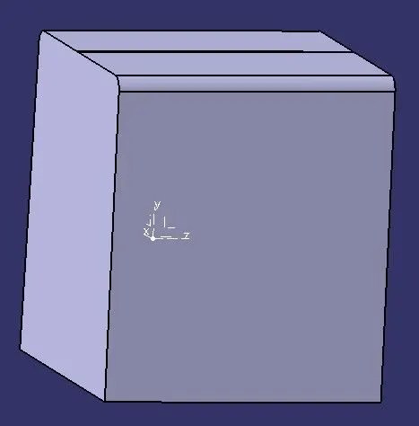
- In the same way create the Rib Cage structure using the sketch-3 and project the curve design using Project 3D element command and create it's Extrude.
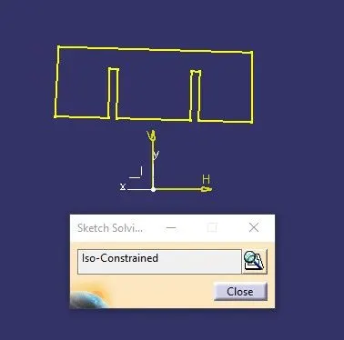
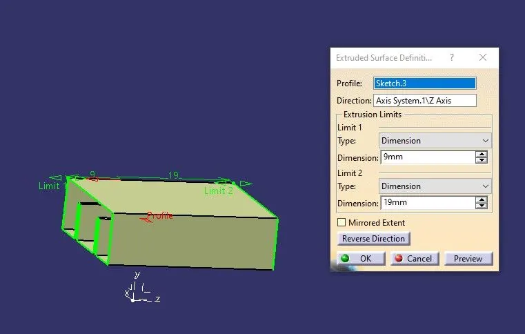
- Now create it as a Solid body using Closed Surface option and remove it in the Pillar Mastersection by Boolean Operations in Part Design.
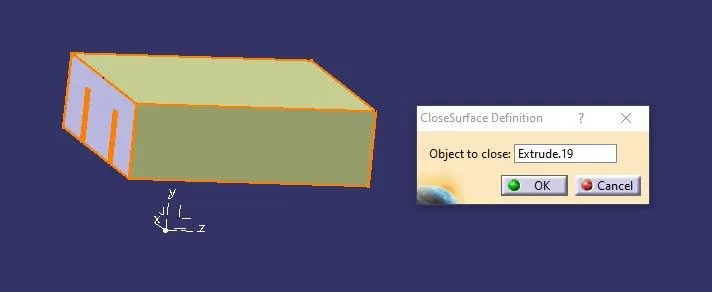
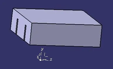
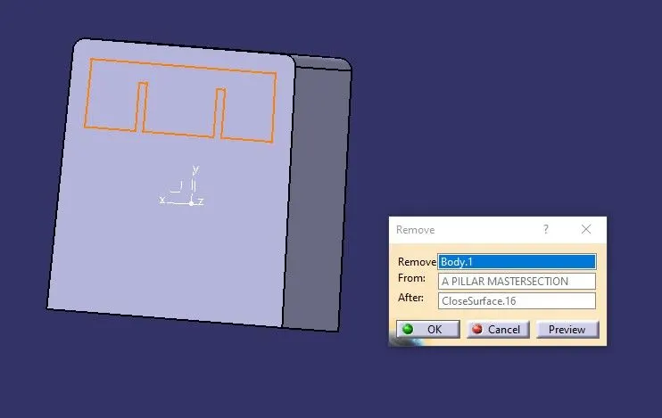
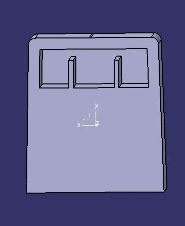
- Now create a Sketch from the lower structure using the Projection 3D element and create an Extrude in Z-axis direction of sketch-4 in Shape Design.
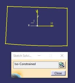
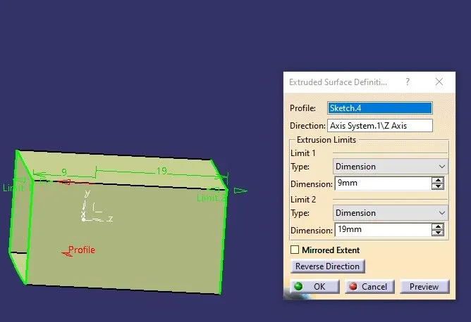
- Just repeat the last before step,create a solid body and remove it from the pillar mastersection in Part Design.
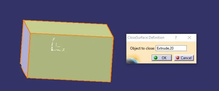
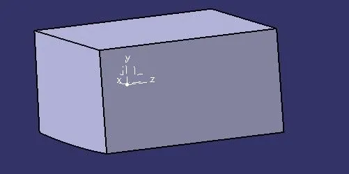
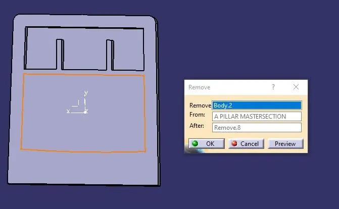
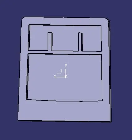
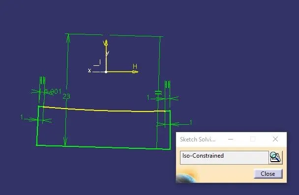
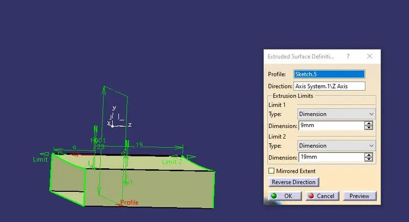
- Create a Sketch as the following from the input guide curve as sketch-5 make an Extrude of it in Shape Design.
- Now create a Solid body from this Extrude and remove it from the Pillar Mastersection in Part Design.
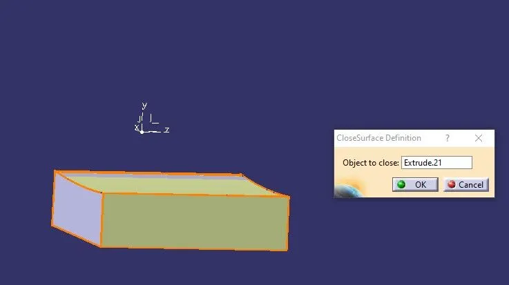
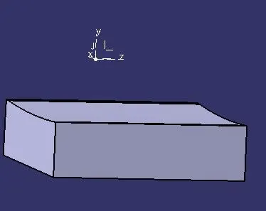
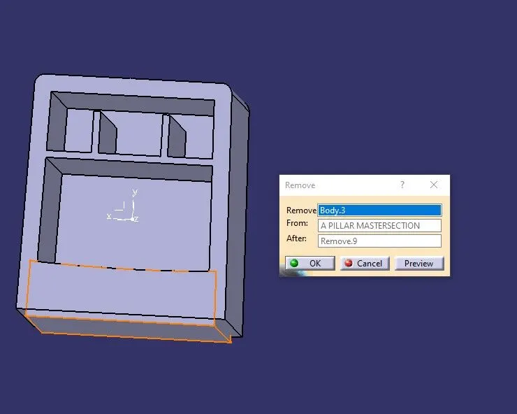
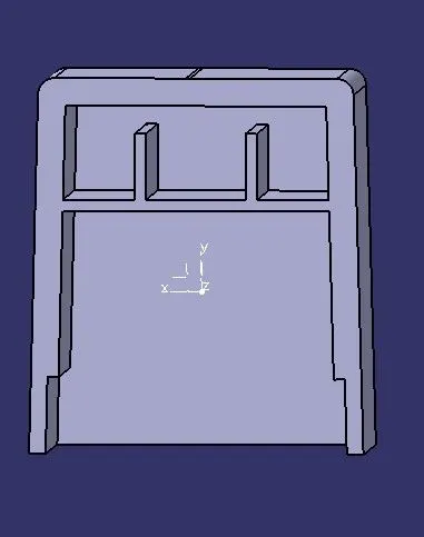
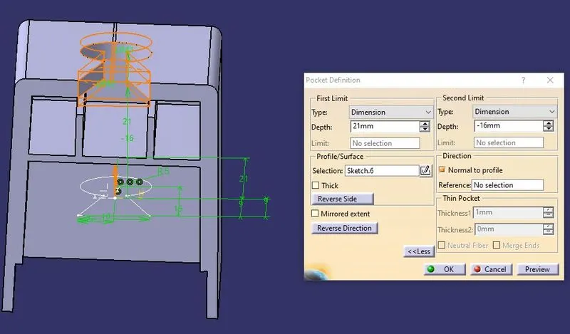
- Now create a sketch as Sketch-6 and perform Pocket operation to create a hole above the Pillar Mastersection in Part Design.
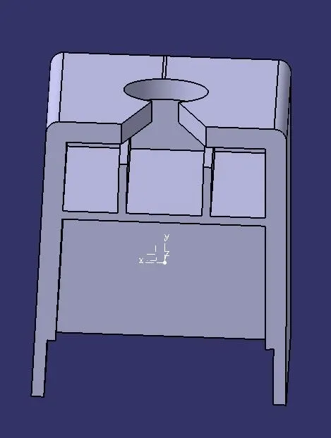
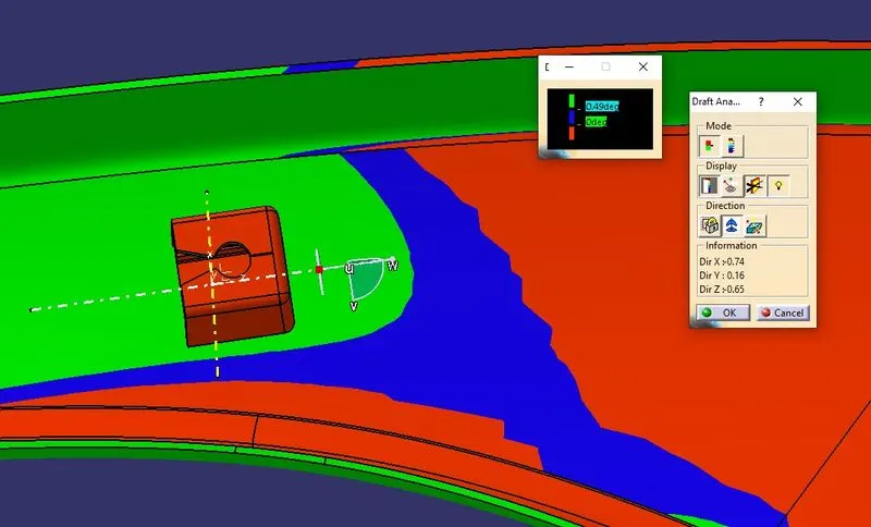
- Now aplly Draft angle of 1.50 on the two sides and back of the Pillar Mastersection.But since we created it using Projection method,the left side is creating an error we are not going to take the left side to consideration by taking Tooling Axis as Pulling Direction and the bottom phase as the Neutral element.
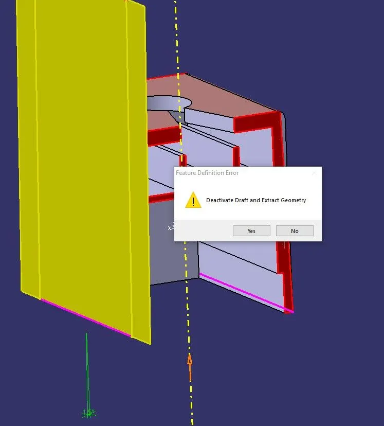
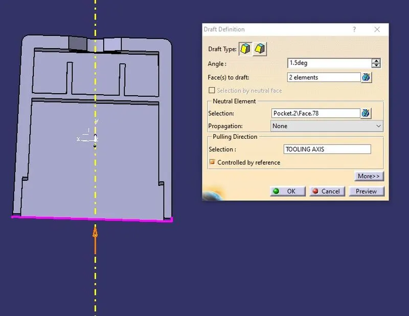
error
- Now a line which passes through the Pillar Mastersection called the SIDE CORE AXIS.This is used in creating drafts in the inside surfaces of the component as the Pulling Direction.Side Core axis is colour noted as White.
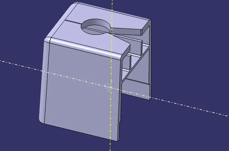
- Now provide edge fillet to the component with the following.
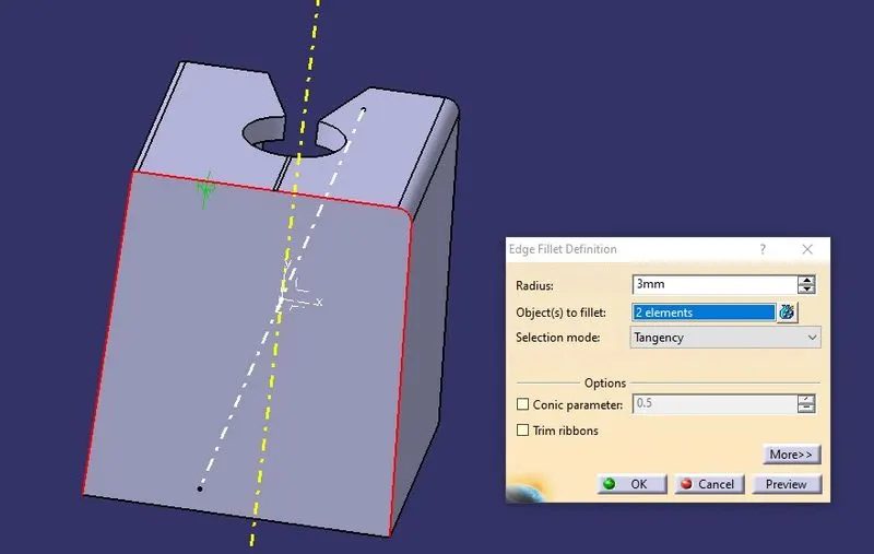
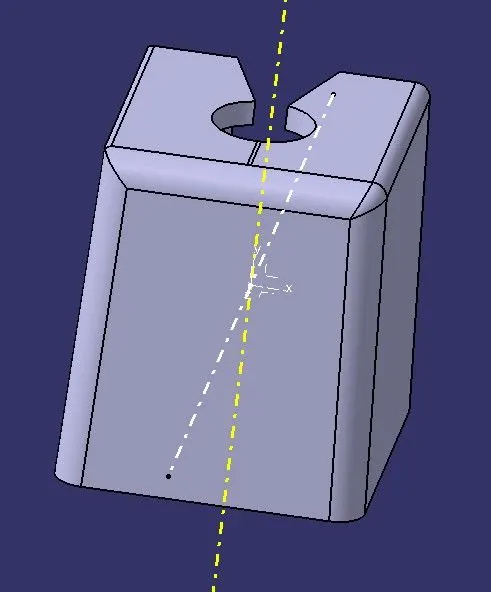
- Perform another edge fillet on the component with the following.
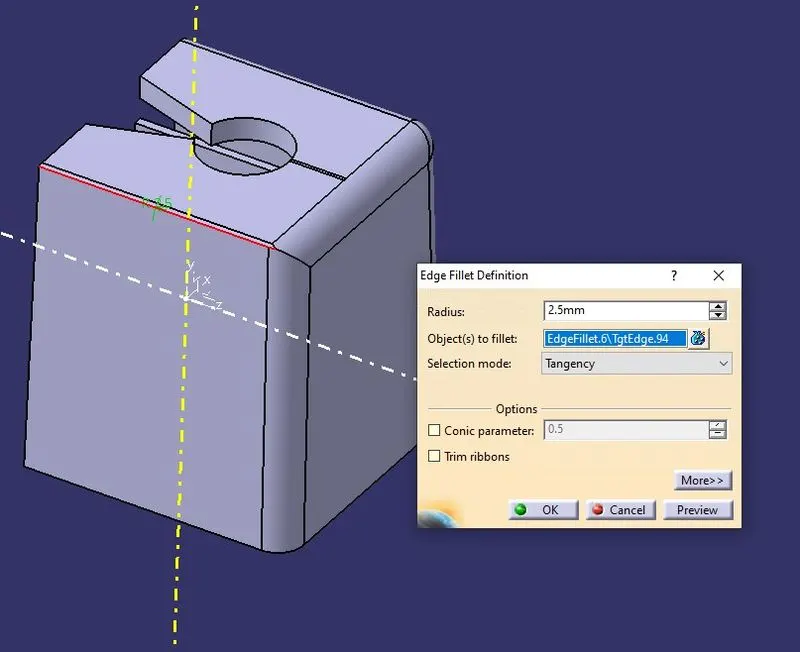
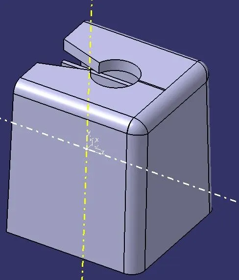
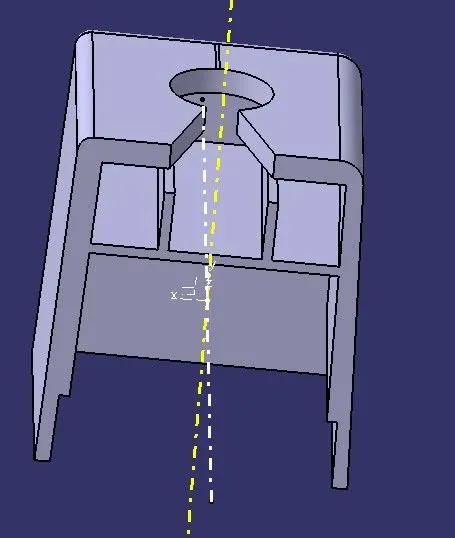
- Now create a Draft as the following on the component.
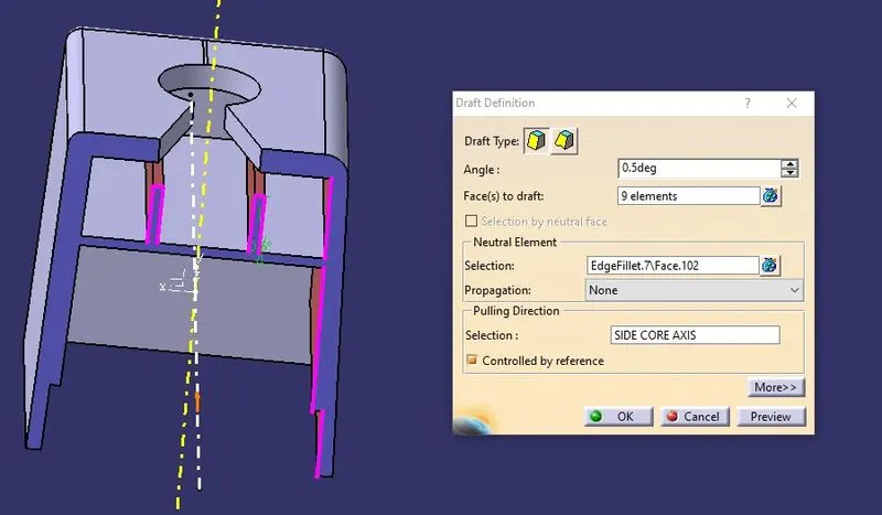
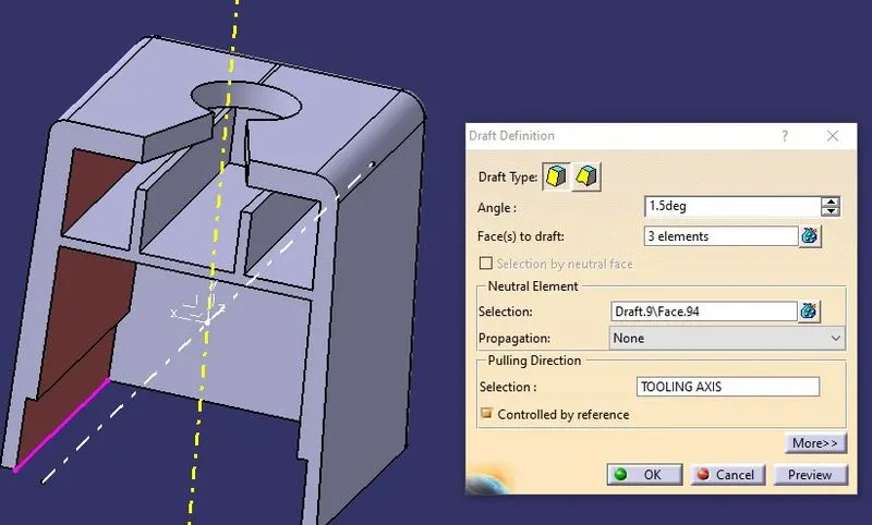
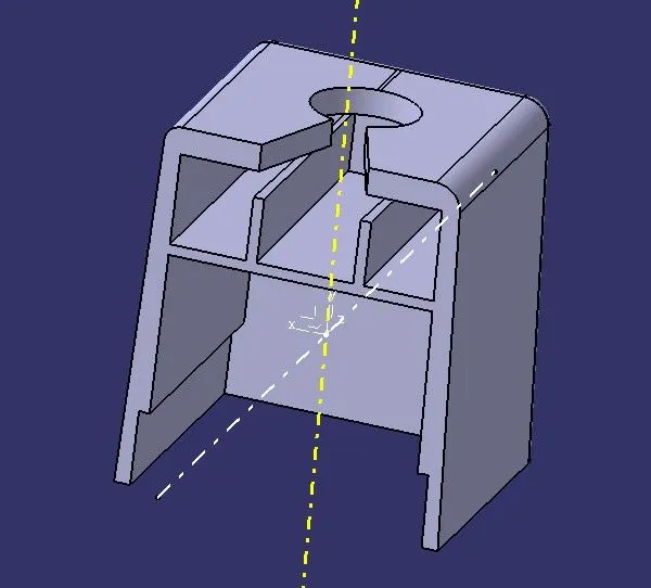
- To maintain proper thickness,create another draft as following.
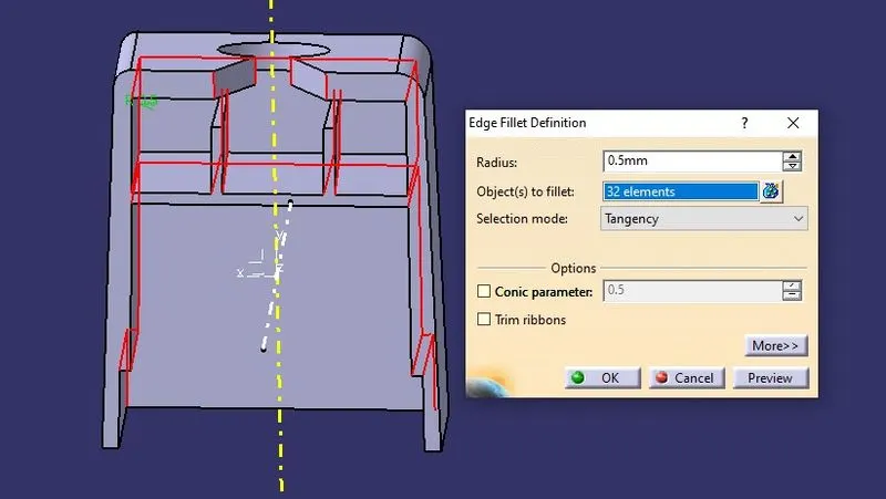
- Now provide edge fillet in the inner surface as following.
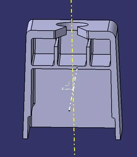
- Before joining it with main Part Body check to see it is in the required position.If not,then adjust it using the TRANSLATE command in the Part Design.
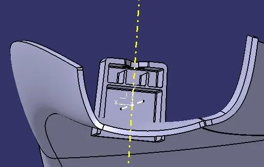
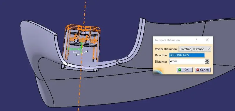
- The Pillar Mastersection appears to be positioned with almost no height,so adjust it to Translate in the Y-axis direction along Tooling Axis.The standard height is 3-6mm,so adjust accordingly.I went with 4mm.
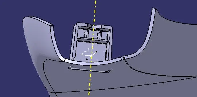
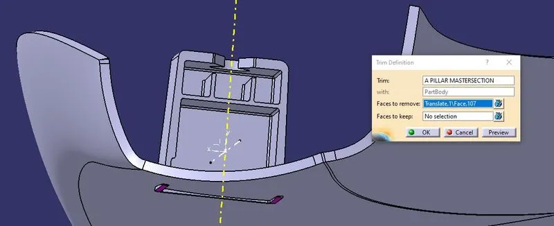
- Now perform UNIOUN TRIM operation and remove the unwanted surface to create a perfect join.
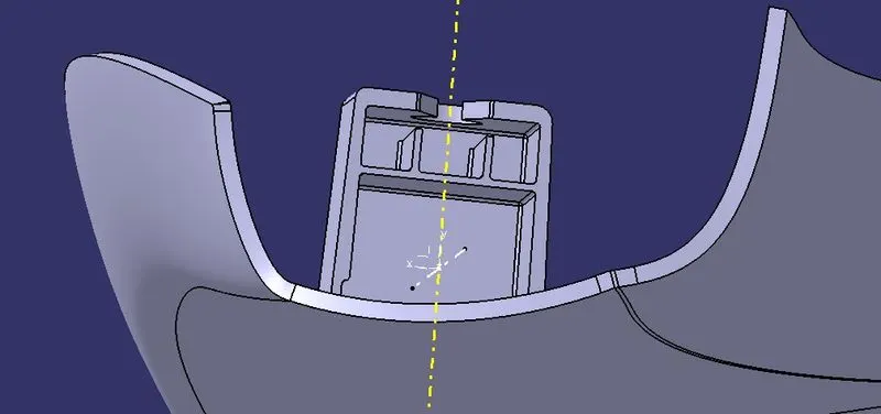
FINAL RESULT
- FRONT VIEW
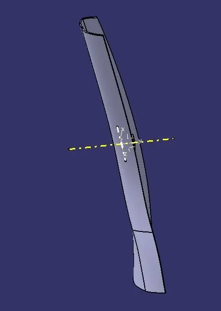
- RIGHT-SIDE VIEW
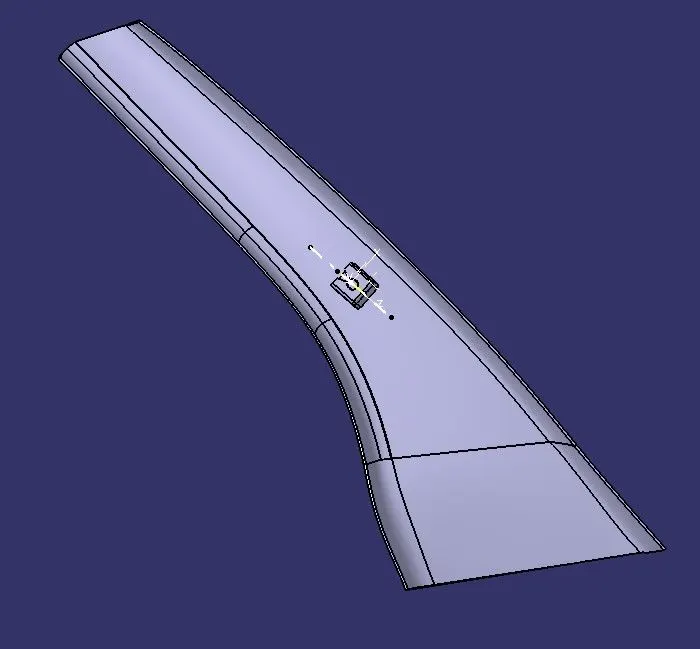
- TOP VIEW
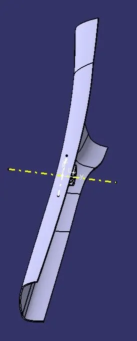
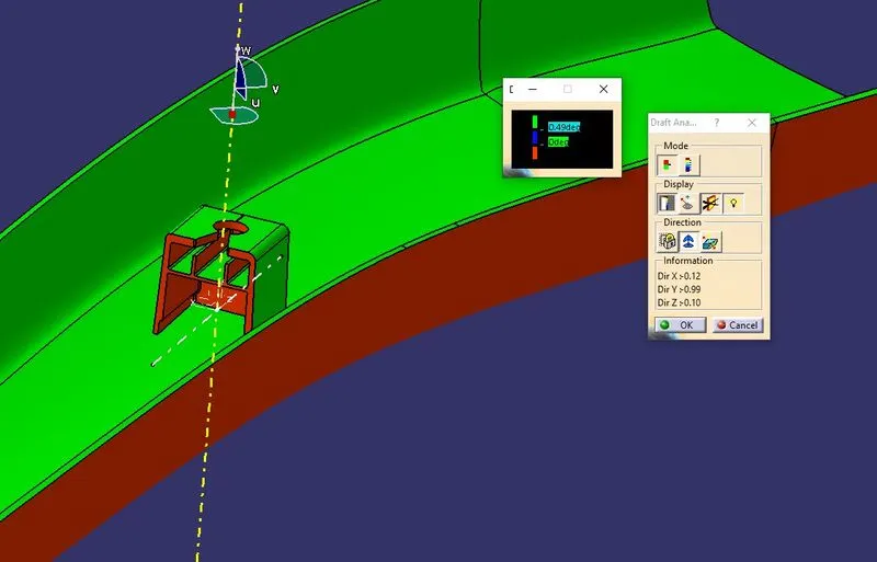
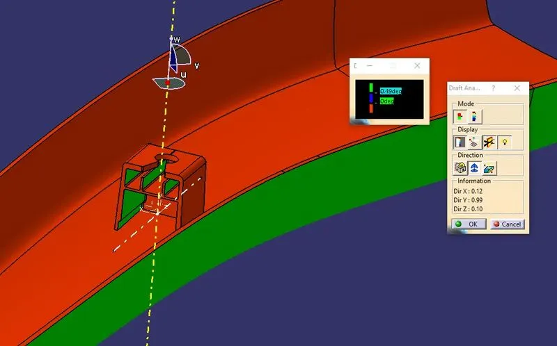
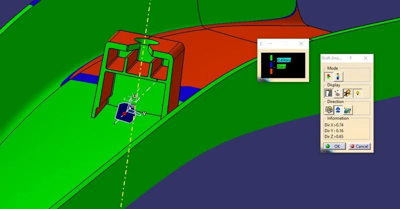
DRAFT ANALYSIS
- FRONT VIEW
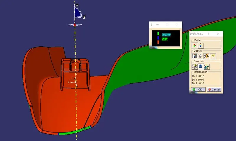
TOOLING AXIS (Draft Angle=0.50 to 30 )
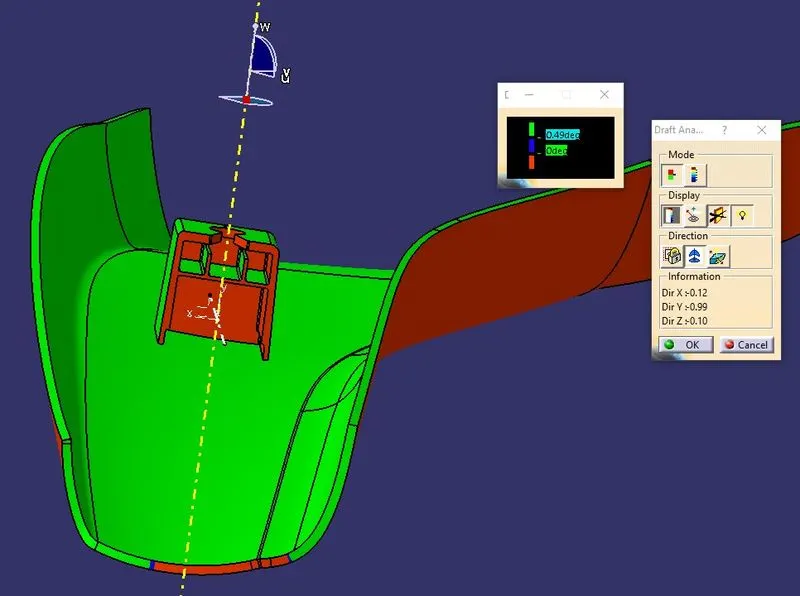
Reverse Direction
SIDE CORE AXIS (Draft Angle=0.50)
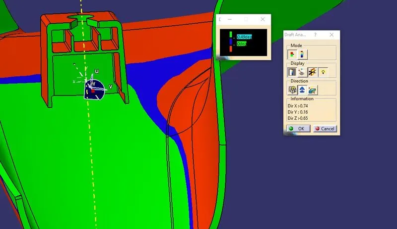
Reverse Direction
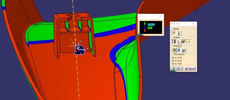
- RIGHT-SIDE VIEW
TOOLING AXIS (Draft Angle=0.50 to 30 )
Reverse Direction
SIDE CORE AXIS (Draft Angle=0.50)
Reverse Direction
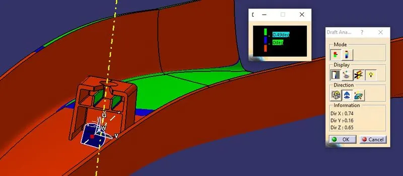
- TOP VIEW
TOOLING AXIS (Draft Angle=0.50 to 30 )
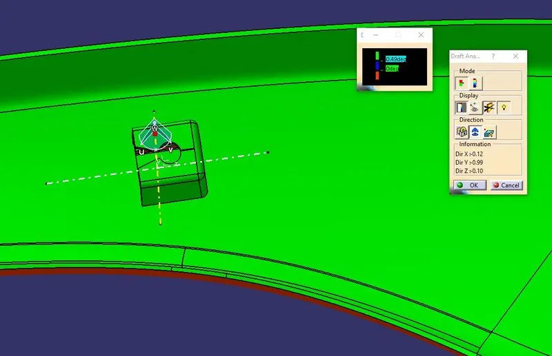
Reverse Direction
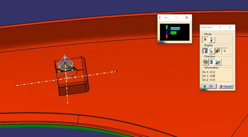
SIDE CORE AXIS (Draft Angle=0.50)
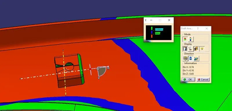
Reverse Direction