Photo Realistic Rendering
CREATION OF AMERICAN CHOPPER BIKE USING SOLIDWORKS
INTRODUCTION
This report is about we can be able to learn and create an AMERICAN CHOPPER bike using a design software called SOLIDWORKS. In this report, first, we will learn what is SOLIDWORKS, next we will learn about the COMMANDS we use while creating different components of the bike, then we will learn about the FEATURES we used while creating these components, then we will learn about how to ASSEMBLE these components, and then we will learn about adding PAINTS and DECALS to each and every component of the bike and then finally we will learn about RENDERING the final assembly of the CHOPPER.
The components which we will learn here are
- Engine
- Chain
- Transmission belt
- Front and Rear wheel
- Front Fork
- Front and Rear fender
- Chassis
- Oil tank
- Kickstand and foot pedal
- Fuel Tank with seat
OBJECTIVE
- To learn the basic commands of SOLIDWORK.
- Get the knowledge of concepts like sketches, features, decals, light and camera angle.
- With the help of a blueprint sketch, we design all the parts of the chopper.
- Assembling all the parts in SOLIDWORK.
- Proper setting of image quality and getting realistic view with the help of photoview 360.
- Rendering of American chopper has been done with help of SolidWorks visualization software.
Design approach
There are two types of approaches in the design procedure.
- Bottom-up approach
- Top-down approach.
Here in this report, we have used the Bottom-up approach, we get a clear idea by defining these terms.
1. Bottom-up approach
The design approach in which the most primary operations are specified first, then combined later to make a larger progressive unit.
2. Top-down approach
Top-down assembly modelling is an assembly-centric modelling method where the assembly design is started at the highest level possible, and individual parts and sub-assemblies are defined within the context of the overall assembly.
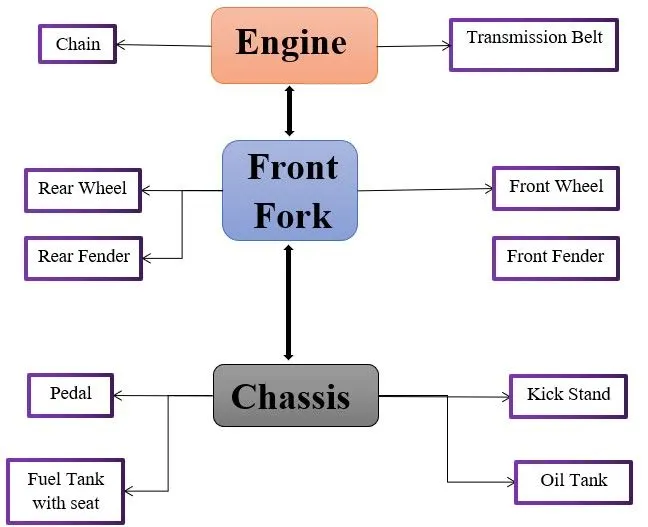
Flowchart of Design Process

Blueprint of the American Chopper
Now we have completed the discussion of how the features work under solid works. Let us see the application of the features in the chopper that we have built. We are going to discuss part by part as shown in the flowchart.
SOLIDWORKS
SolidWorks is a solid modelling Computer-aided design(CAD) & Computer-aided engineering (CAE) computer program published by Dassault Systems, that runs primarily on Microsoft Windows. While it is possible to run Solidworks on an Intel-based Mac with Windows installed, the application's developer recommends against this. SolidWorks does not support macOS.SolidWorks utilizes a parametric feature-based approach which was initially developed by PTC (Creo/Pro-Engineer) to create models and assemblies. The software is written on Parasolid-kernel.
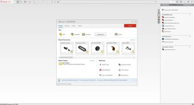
Solidworks interface at the application startup
Building a model in SolidWorks usually starts with a 2D sketch (although 3D sketches are available for power users). The sketch consists of geometry such as points, lines, arcs, conics (except the hyperbola), and splines. Dimensions are added to the sketch to define the size and location of the geometry. Relations are used to define attributes such as tangency, parallelism, perpendicularity, and concentricity. The parametric nature of SolidWorks means that the dimensions and relations drive the geometry, not the other way around. The dimensions in the sketch can be controlled independently, or by relationships to other parameters inside or outside the sketch.
Parameters refer to constraints whose values determine the shape or geometry of the model or assembly. Parameters can be either numeric parameters, such as line lengths or circle diameters, or geometric parameters, such as tangent, parallel, concentric, horizontal or vertical, etc. Numeric parameters can be associated with each other through the use of relations, which allows them to capture design intent.
Features refer to the building blocks of the part. They are the shapes and operations that construct the part. Shape-based features typically begin with a 2D or 3D sketch of shapes such as bosses, holes, slots, etc. This shape is then extruded to add or cut to remove material from the part. Operation-based features are not sketch-based and include features such as fillets, chamfers, shells, applying draft to the faces of a part, etc.
In an assembly, the analogue to sketch relations is mates. Just as sketch relations define conditions such as tangency, parallelism, and concentricity with respect to sketch geometry, assembly mates define equivalent relations with respect to the individual parts or components, allowing the easy construction of assemblies. SolidWorks also includes additional advanced mating features such as gear and cam follower mates, which allow modelled gear assemblies to accurately reproduce the rotational movement of an actual gear train.
Finally, drawings can be created either from parts or assemblies. Views are automatically generated from the solid model, and notes, dimensions and tolerances can then be easily added to the drawing as needed. The drawing module includes most paper sizes and standards (ANSI, ISO, DIN, GOST, JIS, BSI and SAC).
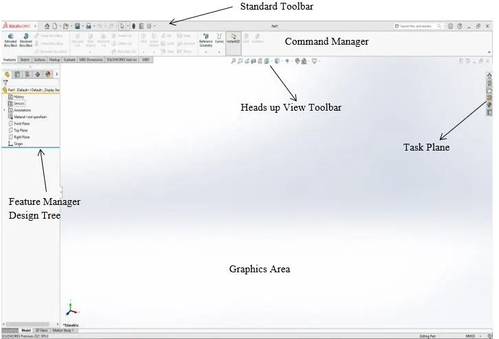
Solidworks interface at the start of a new part design
Terminology
These terms appear throughout the SOLIDWORKS software and documentation.
Origin
Appears as two blue arrows and represents the (0,0,0) coordinate of the model. When a sketch is active, a sketch origin appears in red and represents the (0,0,0) coordinate of the sketch. You can add dimensions and relations to a model origin, but not to a sketch origin.
Sketch Plane
Flat construction geometry. You can use sketch planes for adding a 2D sketch, section view of a model, or a neutral plane in a draft feature.
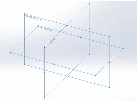
Under Defined Sketch
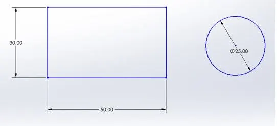
The sketch profile which is created, but not fully defined with either their dimensions or relations is called Under Defined Sketch. The Under Defined Sketch is usually represented in Blue colour in SOLIDWORKS.
Fully Defined Sketch
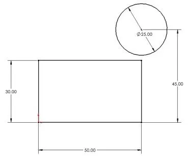
The sketch profile which is created by defining all the required dimensions and relations for a component while sketching is called a Fully Defined Sketch. The Fully Defined Sketch is represented in Black colour in SOLIDWORKS.
Over Defined Sketch
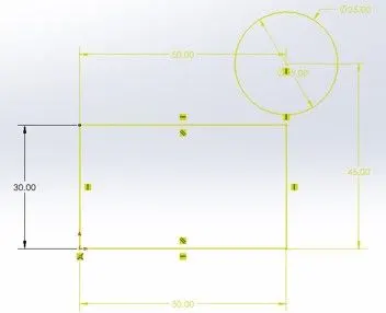
The sketch profile which is created by overly defining all the required dimensions and relations for a component while sketching is called an Over Defined Sketch. The Over Defined Sketch is represented in Yellow colour in SOLIDWORKS.
Axis
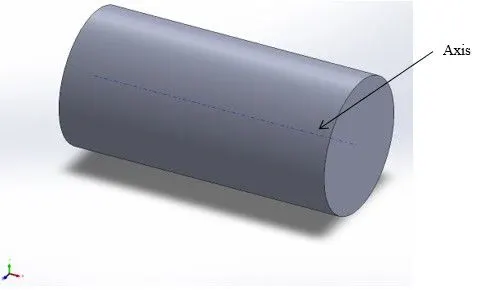
Straight-line is used to create model geometry, features, or patterns. You can create an axis in different ways, including intersecting two planes. The SOLIDWORKS application creates temporary axes implicitly for every conical or cylindrical face in a model.
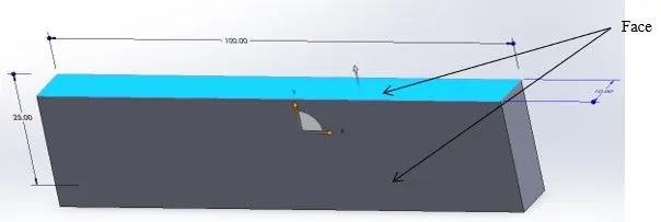
Face
Boundaries that help define the shape of a model or a surface. A face is a selectable area (planar or non-planar) of a model or surface. For example, a rectangular solid has six faces.
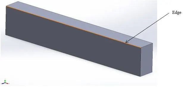
Edge
The location where two or more faces intersect and are joined together. You can select edges for sketching and dimensioning.
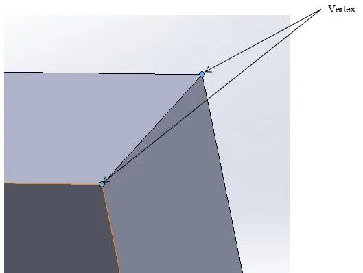
Vertex
The point at which two or more lines or edges intersect. You can select vertices for sketching and dimensioning.
Sketch Commands
These commands are frequently used in the SOLIDWORKS application while creating a 2-D sketch of AMERICAN CHOPPER from the Sketch Toolbar

Sketch Toolbar
Line 
Creates a line from one point to another.

Centreline 
Creates a construction line from one point to another.

Midpoint line 
Creates a line from a point of half the length of a side to another side of the point.

Circle 
Creates a point circle from one point to another point as the radius(r).
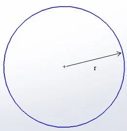
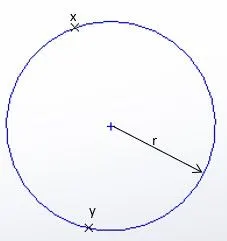
Perimeter Circle 
Creates a circle based on three parameters of x, y and radius.
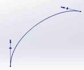
Spline 
Creates a curve geometry is used for creating organic shapes that cannot be created with normal lines and arcs. You can apply curvature constraints at each endpoint. At each through point, you can weigh the tangency vector and control the tangency direction.
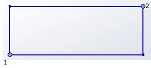
Corner Rectangle 
Creates a rectangle based on the two corner points placed in the Graphics Area.
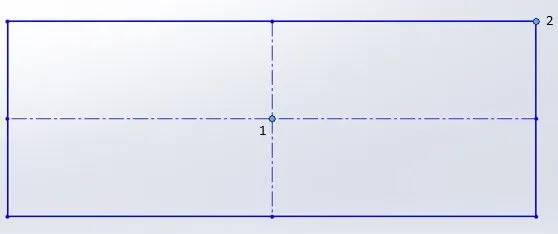
Centre Rectangle 
Creates a rectangle based on the centre point and two points of corners of the rectangle.
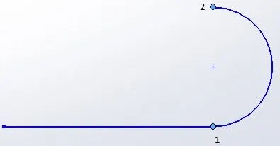
Tangent Arc 
Creates an arc that is tangent to a line by placing two points in the Graphics area.
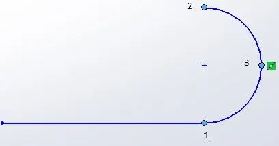
3 Point Arc 
Creates an arc by placing 3 points in the Graphics area.
Sketch Relations
The relations between two sketch entities are called Sketch Relations. The relations we are concerned about in this report are
Horizontal 
This option will assign horizontal relation to the entities as horizontal with respect to the plane.

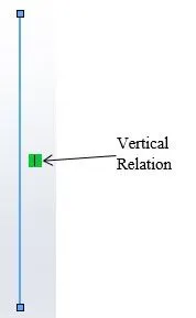
Vertical 
This option will assign vertical relation to the entities as vertical with respect to the plane
Collinear 
This option will assign collinear relation to the entities as collinear with respect to the plane.

Perpendicular 
This option will assign perpendicular relation to the entities as perpendicular with respect to the plane.

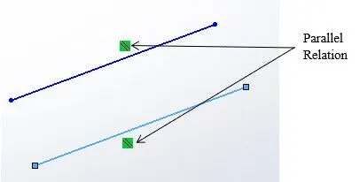
Parallel 
This option will assign parallel relation to the entities as parallel with respect to the plane.
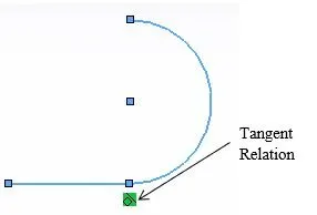
Tangent 
This option will assign tangent relation to the entities as tangent with respect to the plane.
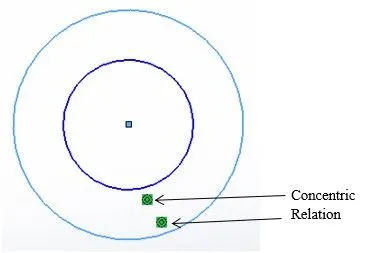
Concentric 
This option will assign concentric relation to the entities as concentric with respect to the plane i.e. The arcs share the same centre point.
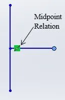
Midpoint 
This option will assign midpoint relation to the entities as midpoint with respect to the plane.
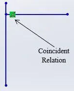
Coincident 
This option will assign coincident relation to the entities as coincident with respect to the plane.
Equal 
This option will assign equal relation to the entities as equal with respect to the plane.
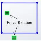
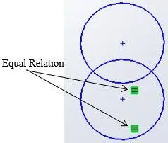
Lengths are equal Radii are equal
Merge 
This option will assign two sketch points or endpoints to merge as a single entity.
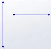
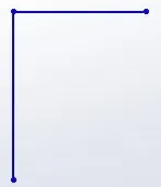
Before merge relation After merge relation
Pierce 
The pierce relation is used in sweeps with guide curves. The relation here is between the guide curve, the origin of the plane and the midpoint of the circles.
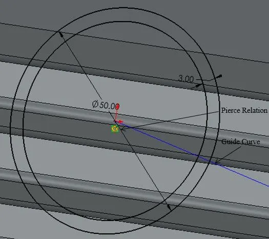
Sketch Features
Sketch Fillet 
The sketch fillet feature is used for rounding up or smoothening up the corners in the sketch before adding any features later on. 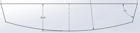
Before sketch fillet
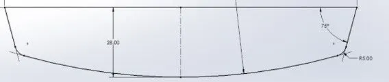
After sketch fillet
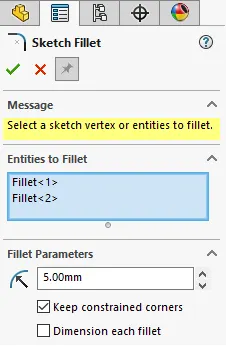
Sketch fillet property manager
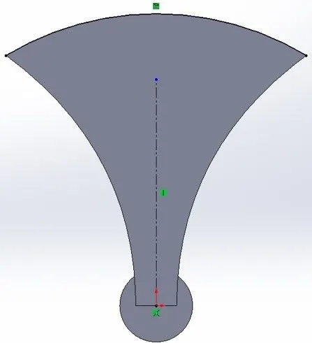
Convert Entities 
The convert entities feature is used for converting a 3-D edge, line, circle etc into a 2-D sketch entity while creating a component.
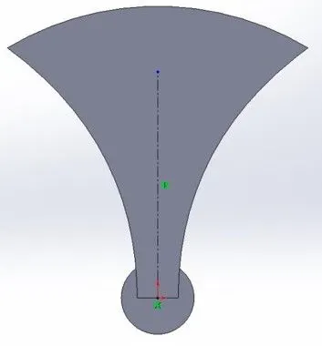
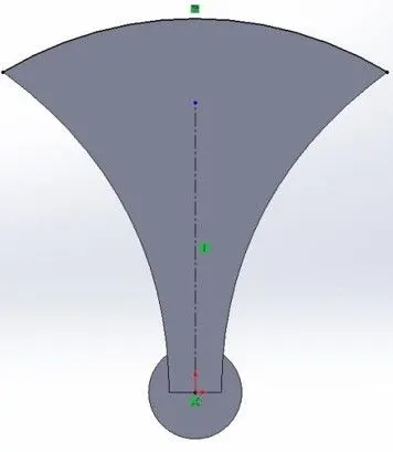
Before Convert Entities After Convert Entities
Offset Entities 
The offset entities feature is used for creating an offset of one or multiple entities in a 2-D sketch.
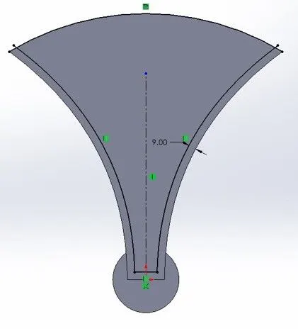
Before using Offset Entities After using Offset Entities
Power Trim 
The power trim feature is used for removing any unwanted sketch portions while creating a 2-D sketch in free motion.
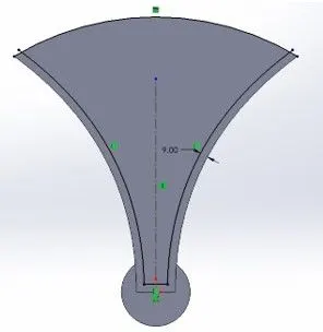
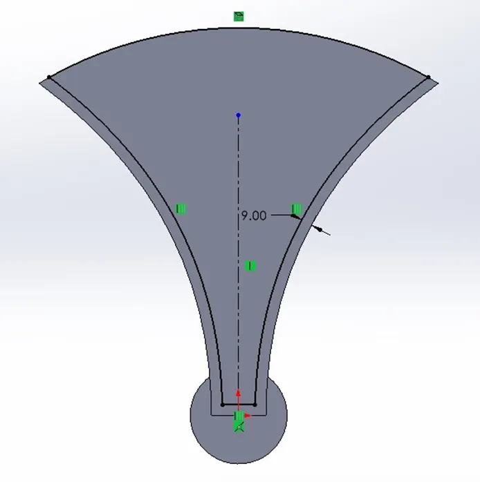
Before using Power Trim After using Power Trim
Mirror Entities
The mirror entities feature is used for creating a mirrored replica of selected sketch entities mirrored about a reference line while creating a 2-D sketch including their relations.
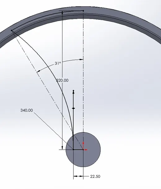
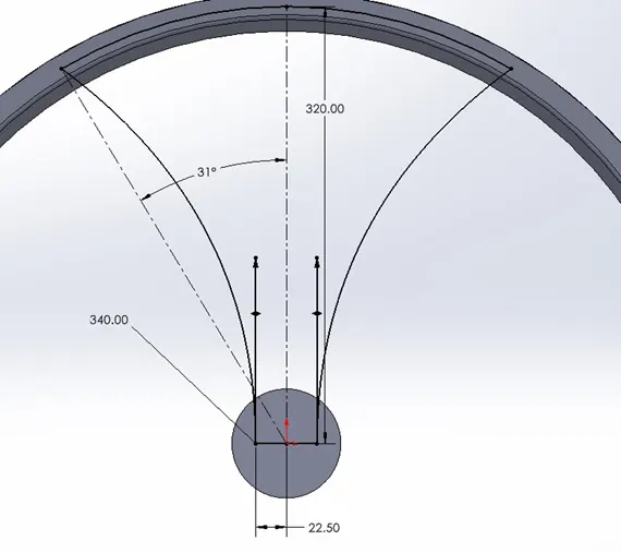
Before using Mirror Entities After using Mirror Entities
Linear Sketch Pattern 
The linear sketch pattern feature is used for creating a linear pattern of selected sketch entities with the desired parameters of x,y and angle θ in the property manager.
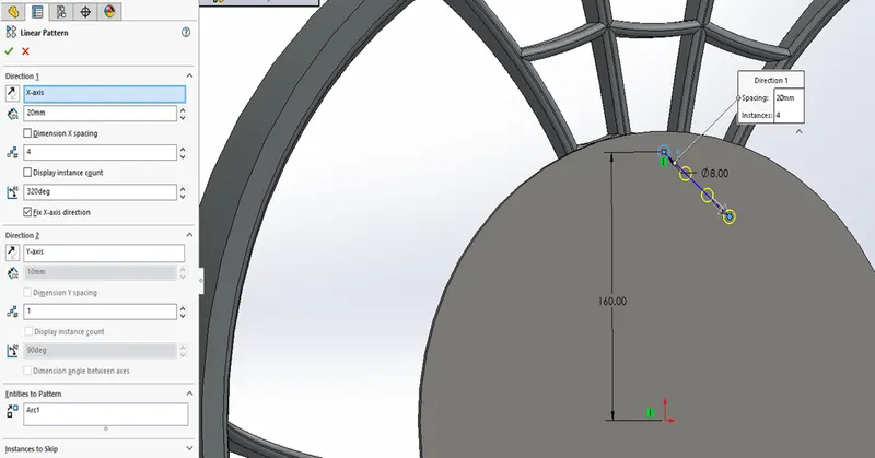
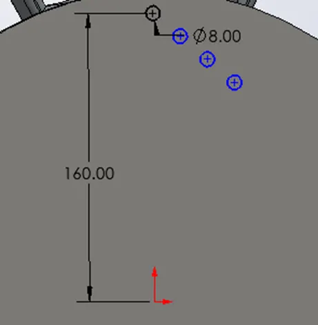
While creating a linear sketch pattern After executing the linear sketch pattern command
Circular Sketch Pattern 
The circular sketch pattern feature is used for creating a circular pattern of selected sketch entities with the desired parameters of no: of instances and angle θ in the property manager.
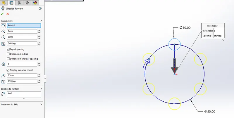
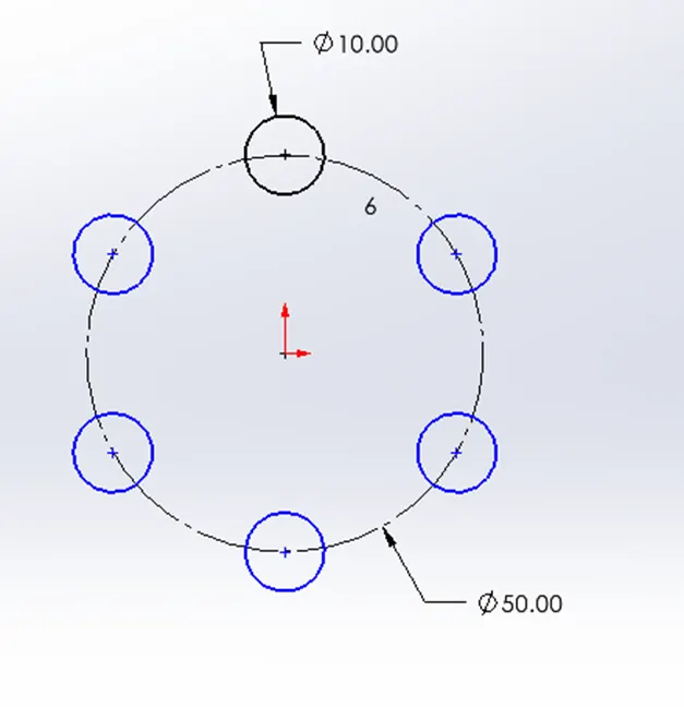
While creating the circular sketch pattern After executing the circular sketch pattern command
Features

Features Tool Bar
The features used in the report to design different parts of AMERICAN CHOPPER are
- Extrude boss
- Fillet
- Chamfer
- Dome
- Revolve boss feature
- Extrude cut
- Shell
- Linear Pattern
- Circular Pattern
- Mirror
- Reference geometry
- Curves
- Split
- Combine
Extrude Boss 
Extrude Boss creates a solid body after finishing a fully defined sketch in the Sketch plane with respect to defined parameters of a component.
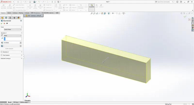
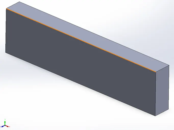
While creating a Boss Extrude feature After executing the Boss Extrude command
Fillet
Fillets are used to soften the corners and edges of the solid body after creating a 3-D component to avoid having any sharp edges on them.
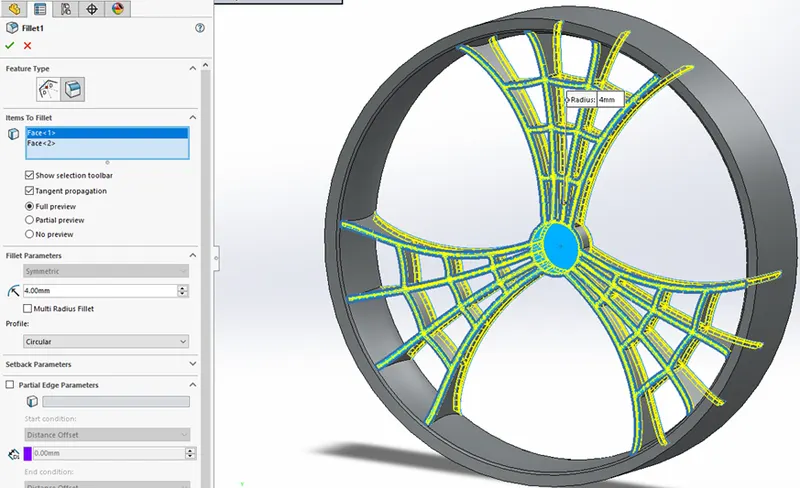
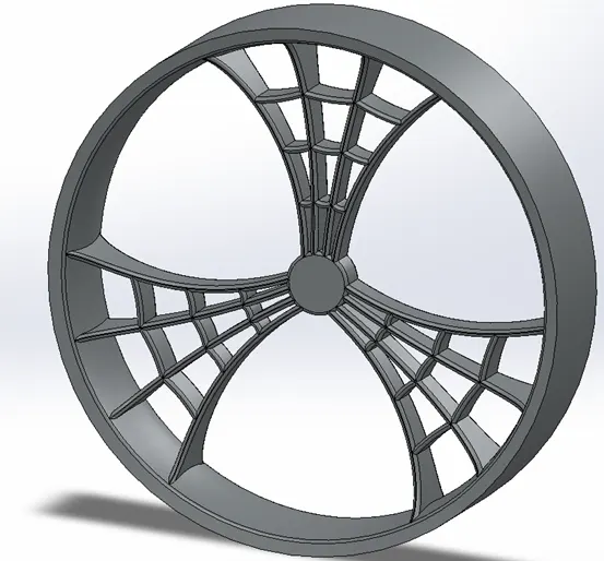
While creating the Fillet feature After executing the Fillet command
Chamfer 
The Chamfer is used to tapper the corners and edges of the solid body after creating a 3-D component to acquire the required shape as per the parameters of distance(D1)-distance(D2) or distance(D1)-angle(θ) type of Chamfer.
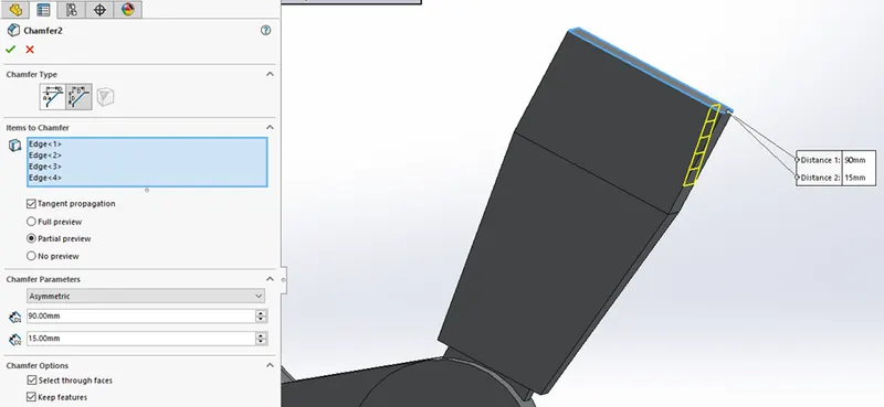
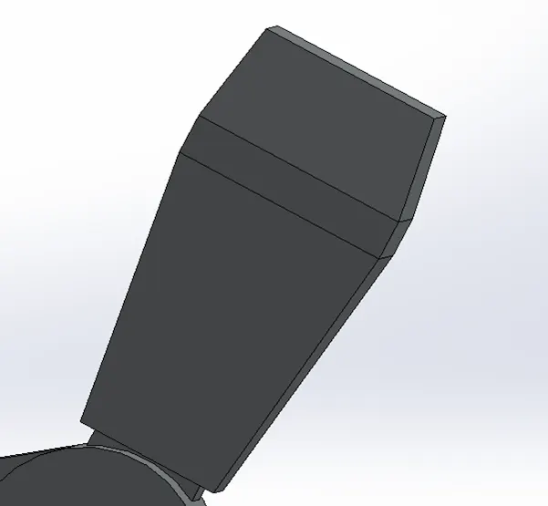
While creating the Chamfer feature After executing the Chamfer command
Dome 
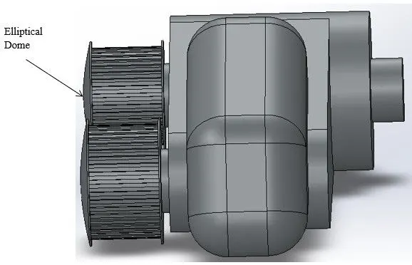
Dome is a hemispherical feature created from the face of a solid body by adding depth to the particular required area. The two types of Domes used in this design are
Elliptical dome
An elliptical dome's shape is a half ellipsoid, with a height equal to one of the ellipsoid radii.
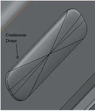
Continuous dome
A continuous dome's shape slopes upwards, evenly on all sides. The Continuous dome shape rises normally to the edges of the polygon.
Revolve Boss Feature 
Revolve Boss feature adds or removes material by revolving one or more profiles around a centre line. You can create revolved boss/bases, revolved cuts, or revolved surfaces. The revolving feature can be a solid, a thin feature, or a surface.
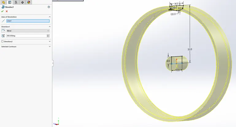
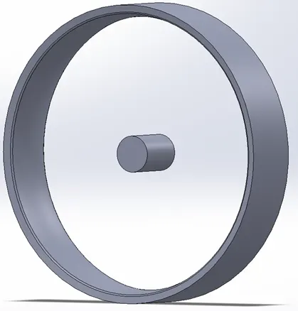
While creating a Revolve Boss Feature After executing Revolve Boss command
Extrude cut 
Extrude cut removes material from the solid body which is specified after generating a 3-D solid body to create a feature in the component.
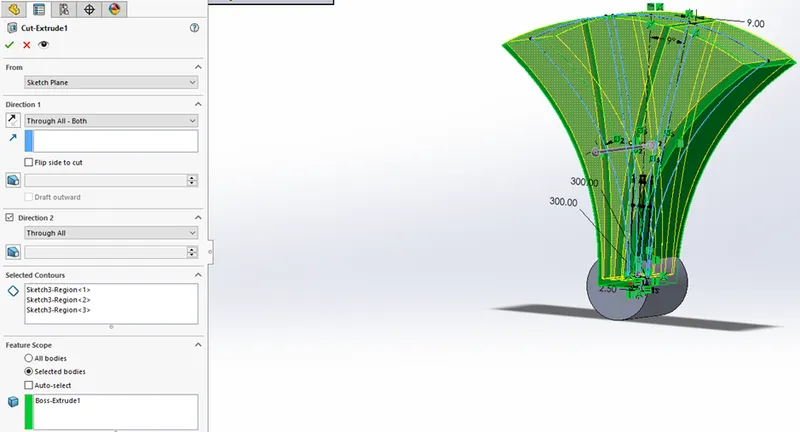
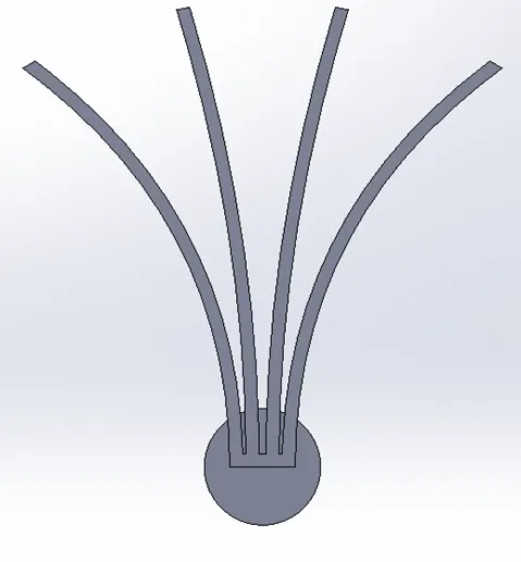
While creating an Extruded Cut After executing Extruded Cut command
Shell 
Shell feature creates a hollow feature in the solid body which is required for a particular component with respect to required parameters in the property manager.
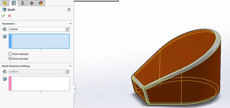
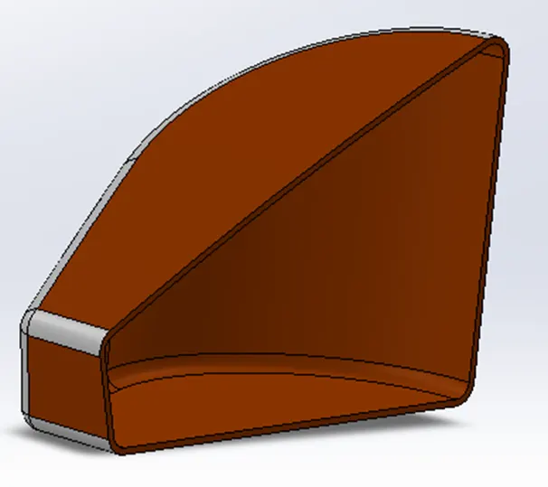
While creating Shell Feature After executing the Shell command
Linear Pattern 
Linear Pattern feature creates a linear pattern of a feature on a solid body by selecting an edge or face as a path and also mentioning the required no: of instances and length in the property manager.
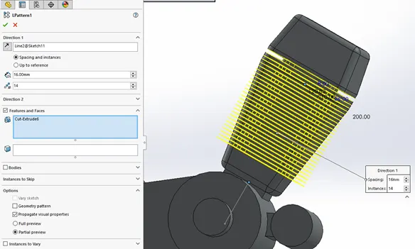
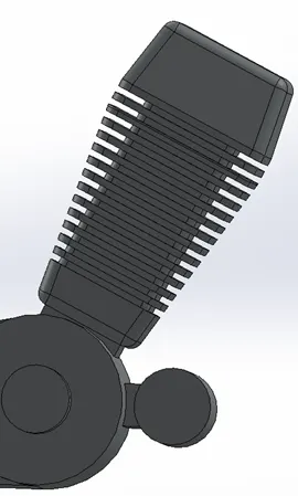
While creating Linear Pattern Feature After executing Linear Pattern
Circular Pattern 
The Circular Pattern feature creates a circular pattern of a feature on a solid body by selecting an edge or face of a circle as a reference and also mentioning the required no: of instances and angle in the property manager.
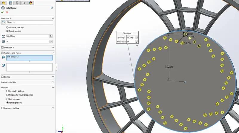
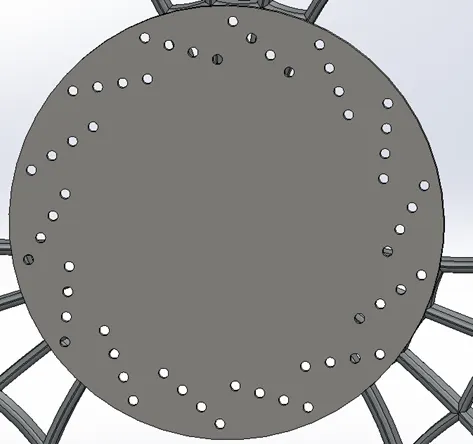
While creating a Circular Pattern feature After executing the Circular Pattern command
Mirror 
The Mirror feature creates an exact mirrored copy of a solid body with respect to the reference plane or axis.
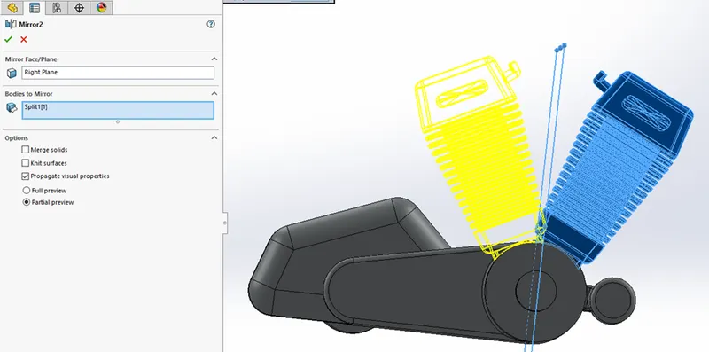
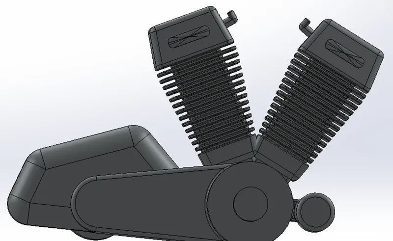
While creating a Mirror body After executing the Mirror command
Reference Geometry 
Reference geometry creates a reference entity for creating a sketch or a solid body. The two main reference geometry used in the report are
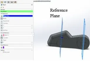
Plane 
Reference Plane creates a Plane at our desired location on the Graphics Area.
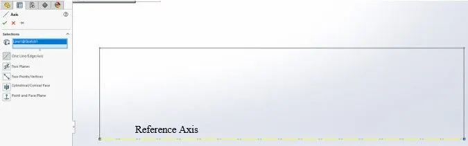
Axis 
Reference Axis creates an Axis at our desired location in the Graphics Area.
Curves 
The curve can be an intersection of two extruding surfaces. The curve which is created can be used as a path for the sketch of the part. The types of Curves features used in this design are
Project Curve 
Project Curve is used for creating an intersecting curve by utilizing two kinds of sketches as a path for further references in the designing processes.
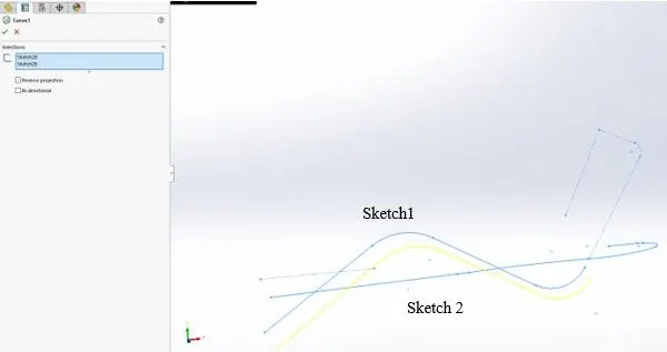
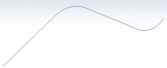
While creating a Project Curve After executing the Project Curve command
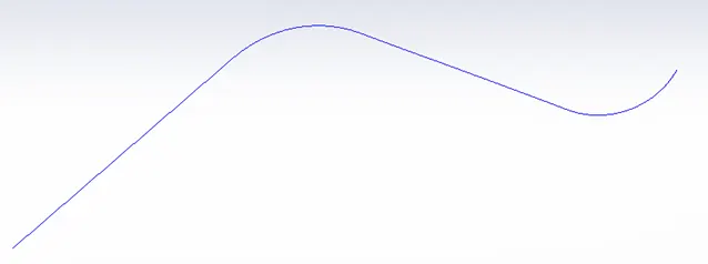
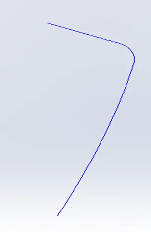
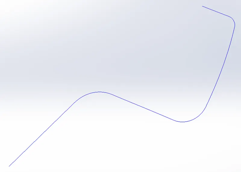
Composite Curve 
The Composite Curve by combining two curves into a curve which can be used as a guide or a path later in the design process.
curve1 curve2
After executing the Composite Curve command
Split 
The Split feature is used to split one or more entities of a solid body into different components even when they are merged together as a single solid body. This feature can also consume cut the component from the solid body according to the need for the design.
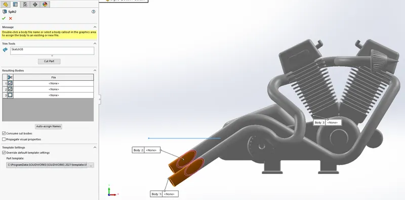
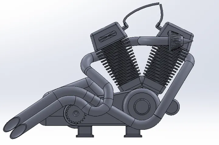
While creating the Split feature After executing the Split command
Combine 
The Combine feature creates a solid body by combining different components and features into a single merged solid body.
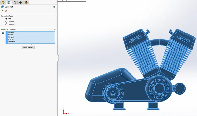
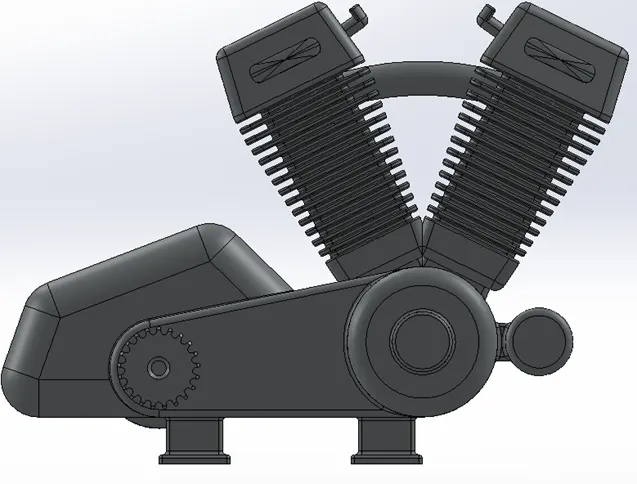
While using the Combine feature After executing the Combine command
Surface Features
Surface modelling is an alternative to solid-body modelling. Essentially, it’s just another tab at the top of the SOLIDWORKS User Interface. Surface modelling is an important tool to have in your box because it not only makes modelling easier, it sometimes makes modelling possible. In other words, there’s some geometry that is impossible to create without using surface features.

Extruded Surface 
Extrude Surface creates a solid body after finishing a fully defined sketch or the face of a surface body with respect to defined parameters of a component.
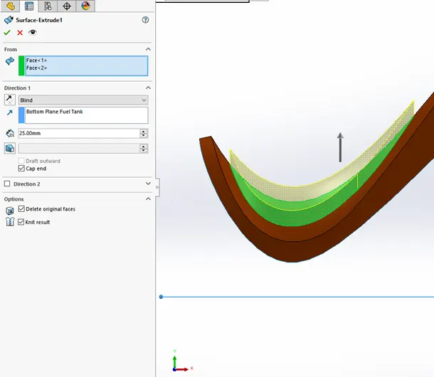
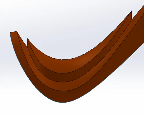
While creating a Surface Extrude After executing Extruded Surface command
Swept Surface 
Swept Surfaces are surfaces that are generated with the help of two guide curves which are used as path and profile of the required surface body.
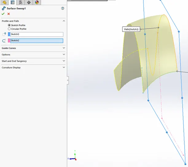
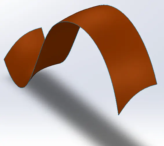
While creating a surface body using Swept Surface After executing Swept Surface command
Trim Surface 
The Trim Surface is used to cut or remove any unwanted surface body areas while designing by selecting the sketch profile and the trim face or edge of the component.
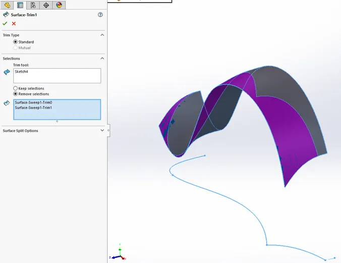
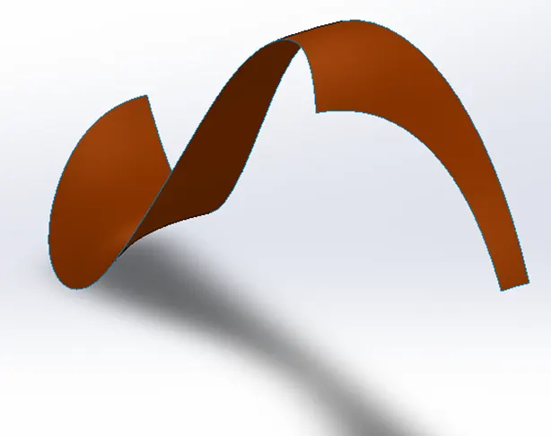
While creating the Trim Surface After executing the Trim Surface command
Lofted Surface 
The Lofted Surface feature creates a shape by making transitions between multiple profiles and guide curves. This tool is very valuable for modelling complex surfaces.
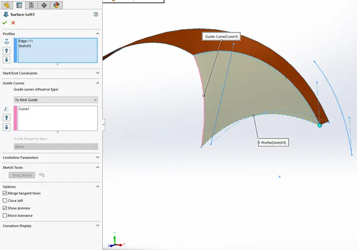
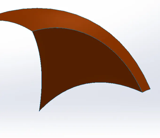
While creating the Lofted Surface After executing the Lofted Surface command
Boundary Surface 
The Boundary surface feature in SOLIDWORKS can be as simple or as complex as you want to make it. It is the basic surface type that most users go to when they need to make a complex shape.
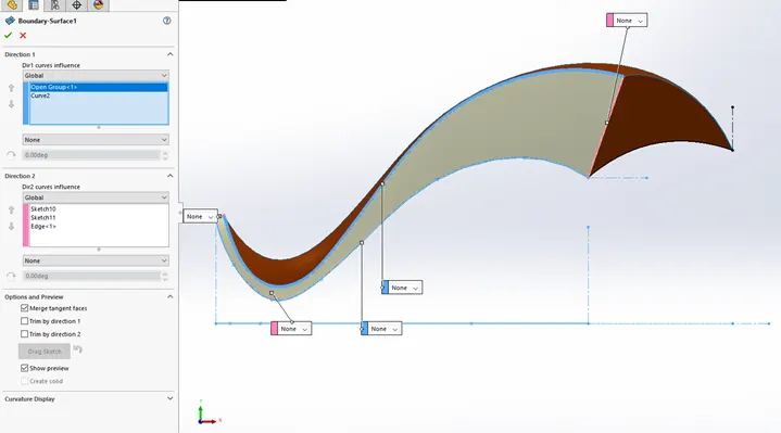
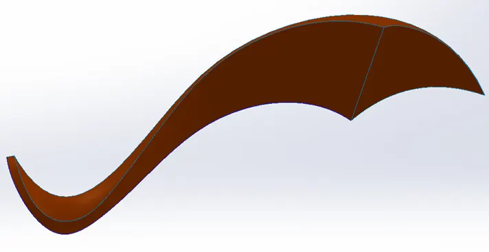
While creating the Boundary Surface After executing the Boundary Surface command
Knit Surface 
The Knit Surface tool allows us to take two or more surfaces and combine them together into one surface.
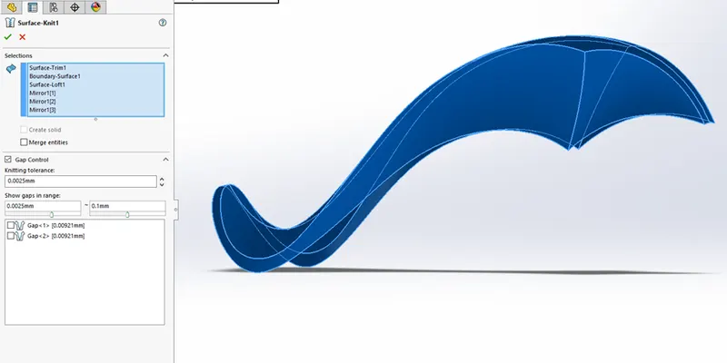
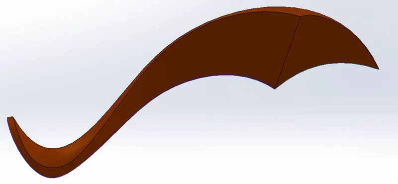
While creating Knit Surface After executing Knit Surface
Split Line 
A split line is used to divide the walls, that is, creates edges. The edge created must result in at least two walls.
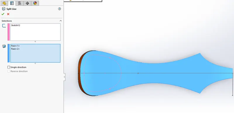
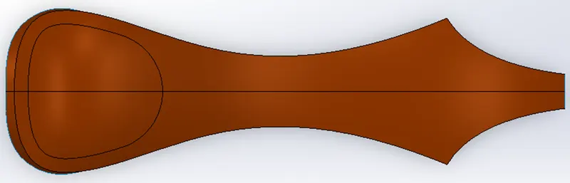
While creating Split Line After executing Split Line
Swept Cut 
Swept Cut command in Solidworks is a very special command that you can do your eccentric cutting operations through a 3D geometry in Solidworks.
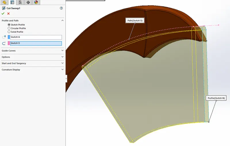
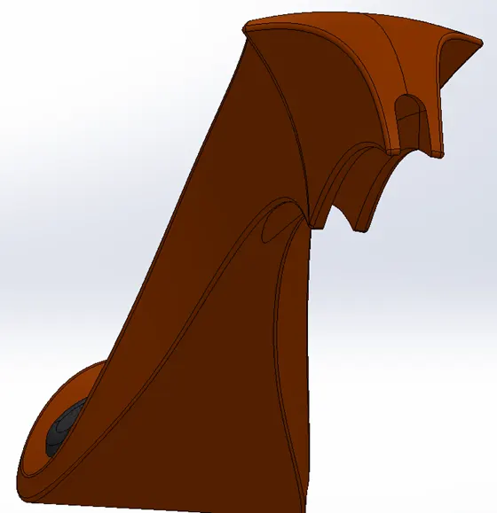
While creating Swept Cut After executing Swept Cut
DESIGNING OF AMERICAN CHOPPER
Engine
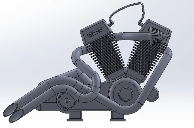
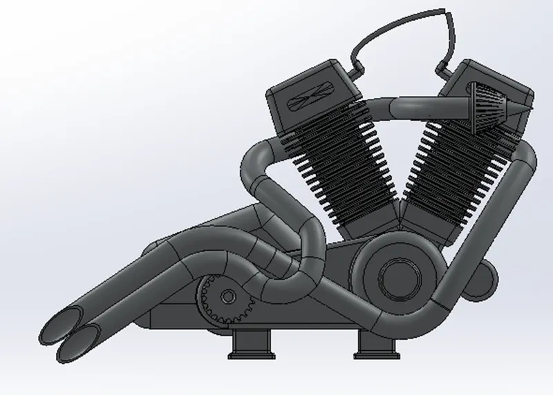
An Engine is a machine designed to convert one or more forms of energy into mechanical energy. It is also called the heart of the bike. The engine consists of parts like a crankshaft, transmission pulleys and motor. The upper part of the crankshaft has cooling fins. The air filters were drawn using spline and the exhaust system is also made with splines and projected curves and sweep feature. The edges of the engine were filleted to give a nice smooth finishing.
Features used to create the Engine are
- Sketch
- Blueprint sketch
- Lines
- Circles
- Boss extrude
- Fillet
- Revolve
- Dome
- Circular pattern
- Chamfer
- Linear pattern
- Mirror
- Cut extrude
- Combine
- Mirror
- Curve
- Composite curve
- Split
Chain
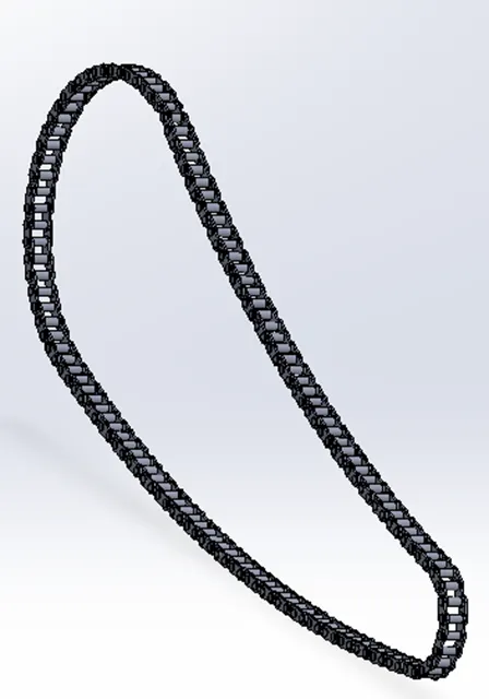
Roller chain or bush roller chain is the type of chain drive most commonly used for transmission of mechanical power on many kinds of domestic, industrial and agricultural machinery, including conveyors, wire- and tube drawing machines, printing presses, cars, motorcycles, and bicycles. It consists of a series of short cylindrical rollers held together by side links. It is driven by a toothed wheel called a sprocket. It is a simple, reliable, and efficient means of power transmission.
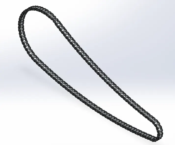
To create a chain first we need to draw the sketch using arcs and lines, the line must be tangent to the arc. Then we draw the sketch of blocks and pins and extrude it, then the pins and blocks were patterned along the path and by calculating the number of pins and blocks. When the whole front side chain pattern is created. Then the front side of blocks can be a mirror to the mid-plane and both sides of the blocks has been created.
Features used to create the Chain are
- Sketch
- Circles
- 3point arc
- Slot
- Block
- Fillet
- Curve pattern
- Mirror
Transmission belt
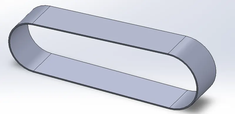
Belts are the cheapest utility for power transmission between shafts that may not be axially aligned. Power transmission is achieved by purposely designed belts and pulleys. The variety of power transmission needs that can be met by a belt-drive transmission system are numerous, and this has led to many variations on the theme. Belt drives run smoothly and with little noise, and provide shock absorption for motors, loads, and bearings when the force and power needed changes. A drawback to belt drives is that they transmit less power than gears or chain drives. However, improvements in belt engineering allow the use of belts in systems that formerly only allowed chain drives or gears.
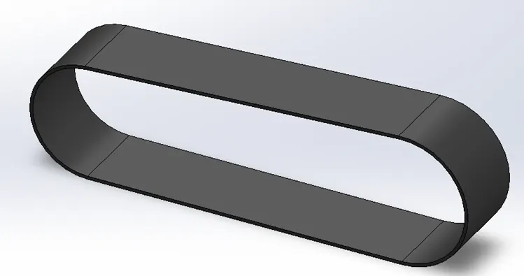
The Transmission belt is located at the round surface of the pulleys. To transmit the power with help of pulleys. The commonly used material for this is rubber. It is a solid body in which transmission belts are filleted.
Features used to create the transmission belt are
- Sketch
- Extrude
- Offset
- Fillet
- Appearance
Front Fork
A motorcycle fork connects a motorcycle's front wheel and axle to its frame, typically via a yoke, also known as a triple clamp, which consists of an upper yoke joined to a lower yoke via a steering stem, a shaft that runs through the steering head, creating the steering axis. Most forks incorporate the front suspension and front brake and allow the front wheel to rotate about the steering axis so that the bike may be steered. Most handlebars attach to the top clamp in various ways, while clip-on handlebars clamp to the fork tubes, either just above or just below the upper triple clamp.
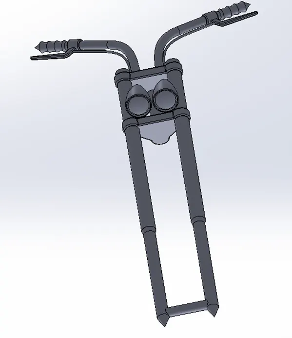
The Front Fork is attached to the whole chassis and the front wheel. It also includes parts such as the front wheel, front fork, handlebars, headlights, brake and clutch levers. First, the half portion of the front fork has been created and the whole body is mirrored about the plane. Projected curves were used to model the handles and the cables. The handles of the front fork were given grips.
Features used to create the Front fork are
- Sketch
- Lines
- Revolve
- Circle
- Fillets
- Linear pattern
- Spline
- Extrude cut
- Dome
- Curve
- Sweep
- Plane
- Mirror
- Combine
Front and Rear wheel
Motorcycle wheels are made to cope with radial and axial forces. They also provide a way of mounting other critical components such as the brakes, final drive and suspension. Wheels, and anything directly connected to them, are considered to be unsprung mass. Traditionally motorcycles used wired-spoke wheels with inner tubes and pneumatic tyres. Although cast wheels were first used on a motorcycle in 1927, it would not be until the 1970s that mainstream manufacturers would start to introduce cast wheels on their road-going motorcycles. Spoked wheels are usually made using steel spokes with steel or aluminium rims. Cast wheels are predominantly made from an aluminium-alloy, but can also be made from more exotic materials, such as magnesium content alloy or carbon fibre.
Front Wheel
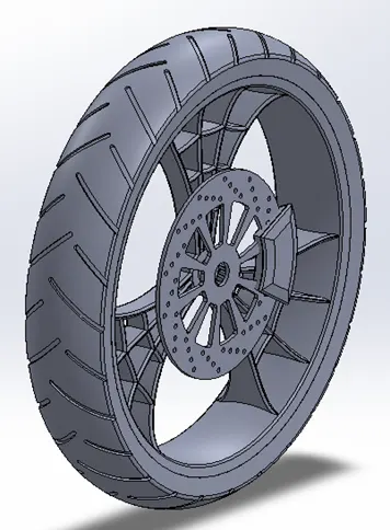
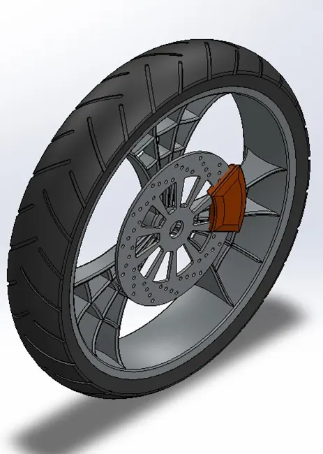
Front-wheel is having a larger diameter than the rear wheel. To manage impact better than the rear. Front-wheel experiences the greatest force during braking. First, the rim was created by revolve boss feature and the spider-webbed spokes were created by using splines and offsetting them. Then the spider-webbed spokes were patterned to the rim. On rim rotor and calliper were modelled. The tire was modelled using revolve and threads were applied.
Features used to create the Front-wheel are
- Sketch
- Lines
- 3-point arc
- Sketch fillet
- Revolve
- Spline
- Extend
- Trim
- Cut extrude
- Offset
- Revolve cut
- Circular pattern
- Chamfer
- Fillet
Rear Wheel
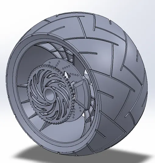
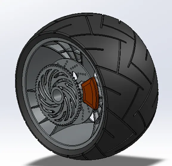
The rear tire is primarily used for accelerating the vehicle and moving the vehicle forward. It is wider than the front wheel to give stability to the vehicle and a sprocket is added to link the wheel and engine with the help of the chain.
Features used to create the Rear-wheel are
- Sketch
- Lines
- 3-point arc
- Sketch fillet
- Revolve
- Spline
- Extend
- Trim
- Extrude cut
- Offset
- Revolve cut
- Circular pattern
- Chamfer
- Fillet
Front and Rear Fender
Fender is the American English term for the part of an automobile, motorcycle or other vehicle body that frames a wheel well (the fender underside). Its primary purpose is to prevent sand, mud, rocks, liquids, and other roads spray from being thrown into the air by the rotating tire. Fenders are typically rigid and can be damaged by contact with the road surface. Fender is known as Mudguard in India.
Front Fender
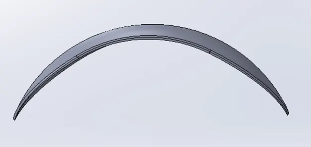
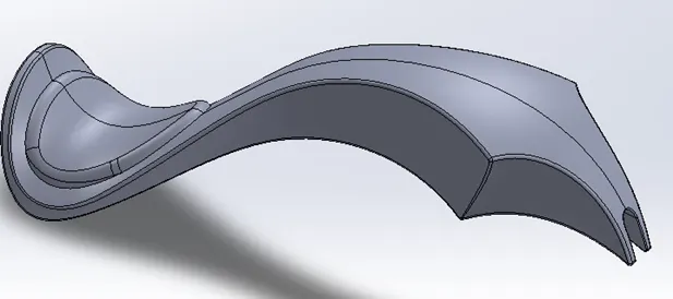
Here we revolved the sketch using an axis and created a half curved solid body. Some sharp edges are designed on both sides of the fender by using the split tool the material is removed. The edges of the fender are filleted.
Features used to create the Front fender are
- Sketch
- 3-point arc
- Offset
- Extend
- Trim
- Revolve
- Spline
- Fillet
Rear Fender
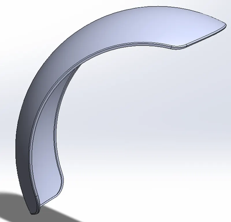
The same procedure is used to make the rear fender as it was used in the front fender. Only the difference between the two are sizes according to the size of the tire.
Features used to create the Rear fender are
- Sketch
- 3-point arc
- Extend
- Trim
- Revolve
- Spline
- Fillet
- Shell
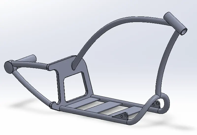
Chassis
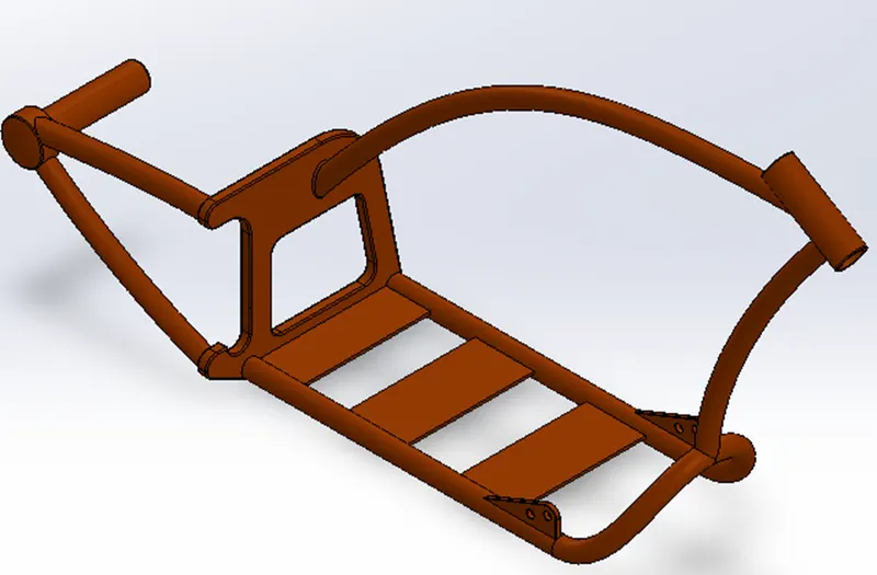
The motorcycle chassis is for a motorcycle the same as the skeleton for a human being. Often made of materials highly resistant to torsional and tensile forces such as steel or iron itself, the frame of a motorcycle is a series of plates, slats and bars that run the length of the motorcycle throughout, serving as a fulcrum of a large part of the elements that make up the vehicle, including the driver. It holds all the components such as the front fork, pedals, kickstand, oil tank, engine, gas tank and rear wheel. The modelling of the chassis starts with using a chopper image for reference. It uses features such as an extruded boss, splines, and revolving parts, making mirrors and sweeping. In the end whole part was created by using a fillet and it gives a nice appearance to the chassis and the sharp edges gets round.
Features used to create the Chassis:
- Blueprint sketch
- Splines
- Curves
- Mirror
- Boss extrude
- Extrude cut
- Chamfer
- Dome
- Split
- Revolve
- Combine
Oil tank
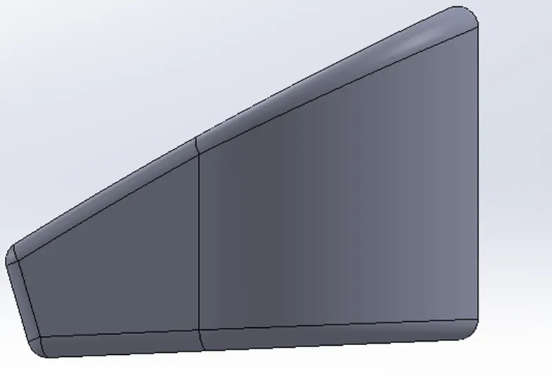
The purpose of an oil tank is not simply to store oil, an oil tank has two other main functions:
- An oil tank allows oil to settle and this reduces the likelihood of the oil foaming.
- The oil tank is designed in such a way as to allow the oil to be cooled efficiently when the engine is in operation.
The base of the oil tank is sketched on the top plane and extruded above to attain the structure of the oil tank and another sketch is added on the mid-plane it is then extruded and then combined together and at the end, a shell function is used to make part hollow from inside. Fillet is applied on the outer edges to make it round.
Features used to create the Oil tank are
- Lines
- 3-point arc
- Boss extrude
- Combine
- Fillet
- Shell
Kickstand
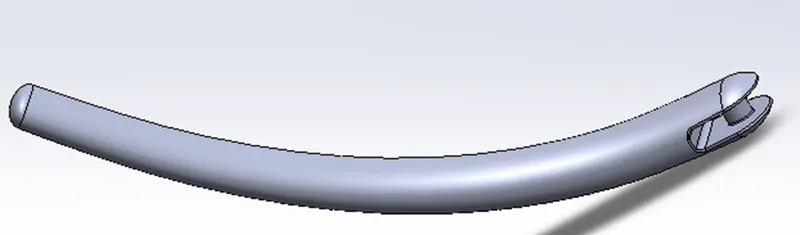
A kickstand is a device on a bicycle or motorcycle that allows the bike to be kept upright without leaning against another object or the aid of a person. A kickstand is usually a piece of metal that flips down from the frame and makes contact with the ground. It is generally located in the middle of the bike or towards the rear. While designing the kickstand first we have created a sketch based on an additional plane, the part created by using the loft feature and dome has been applied on both sides of a kickstand. Then at the bottom part to rest the kickstand, the flat surface has created by using a sketch. We have used extruded cut for assembly purposes. After the part has been created, we applied fillets to the edges and at the joints of the part.
Features used to create the kickstand are
- Sketch
- Ellipse
- Splines
- Pierce
- Loft
- Cut extrude
- Boss extrude
- Split
Pedal
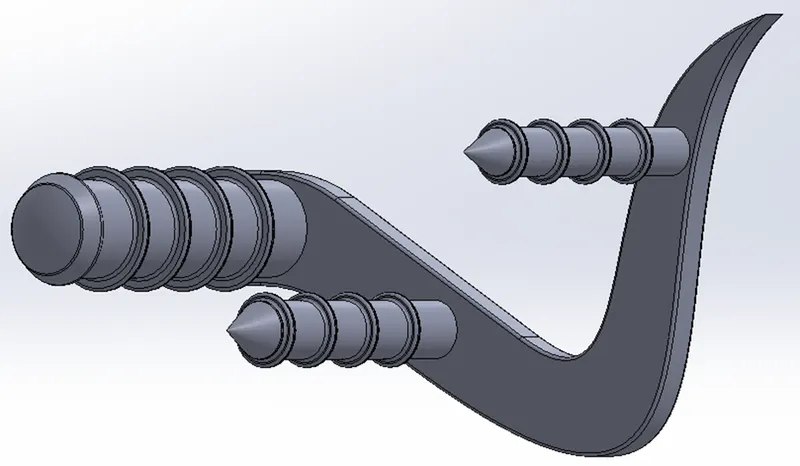
A pedal is a strong rigid body used to rest the foot while riding a bike. The various features are used to create the pedal are splines, fillets, dome, chamfer and linear pattern.
Features used to create the Pedal are
- Sketch
- Lines
- Circles
- Fillet
- Revolve
- Dome
- Chamfer
- Linear pattern
Fuel Tank with seat
A vehicle’s fuel tank is crucial to its functioning. Fuel-driven vehicles need either petrol or diesel, and the tank is the source for it. Whether it is a car or a bike, a vehicle’s engine is dependent on the fuel tank for continuous fuel supply. A motorcycle seat (sometimes saddle) is where the rider sits, and may also accommodate a passenger. The most common type of motorcycle seat is a dual saddle or bench seat, which runs along the top of the chassis and is long enough for a passenger to straddle the motorcycle behind the rider.
This part is mainly made with splines and sweep features. The half part of the gas tank is first created and then it is then mirrored about the plane. The two separated parts were made single part by using the knit feature. The gas tank covers the oil tank and engine, and also it acts a shield to prevent the heat from the engine. The seat was modelled on the top of the gas tank. The fillets were added to the edges of the gas tank. At the end shell feature were added to make it hollow from the inside.
Features used to create the Gas tank are
- Blueprint
- Sketch
- Spline
- Surface sweep
- Surface trim
- Surface boundary
- Surface loft
- Curve
- Mirror
- Surface knit
- Surface extrudes
- Fillet
- Extrude cut
- Shell
PAINTS and DECALS
Paints
Engine
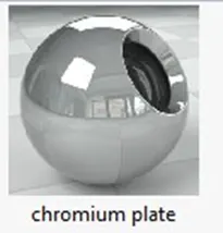
The appearance is given to the Engine as Chromium Plate.
Chain
The appearance given to the Engine is Chromium Plate.
Transmission belt
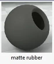
The appearance given to the Transmission Belt is matte rubber.
Chassis
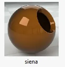
The appearance given to the Chassis is Siena.
Front and Rear wheel
The appearance given to the Wheels is Chromium plate for Rim and Rotor, Siena for Brake pad and Matte Rubber for Tyres.
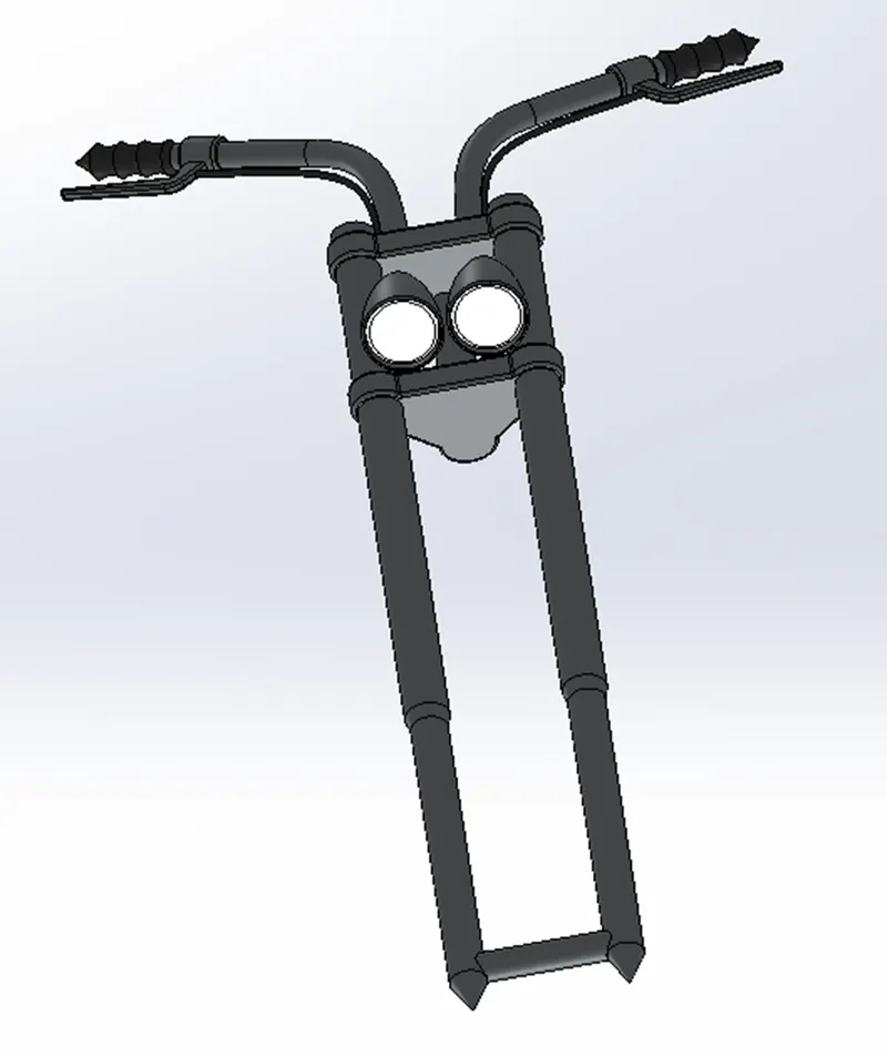
Front Fork
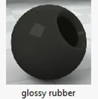
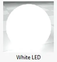
The appearance given to the Front Fork is Chromium Plate, Handle grip and brake wires is Glossy Rubber and Headlight is White Led.
Front and Rear fender
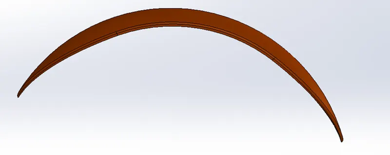
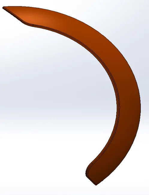
The appearance given to the Fender is Siena.
Oil tank
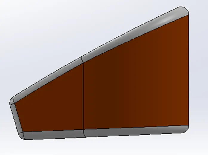
The appearance given to the Oil Tank is Siena.
Kickstand
The appearance given to the Kickstand is Chromium Plate.
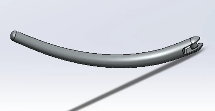
Pedal
The appearance given to the Pedal is Chromium Plate.
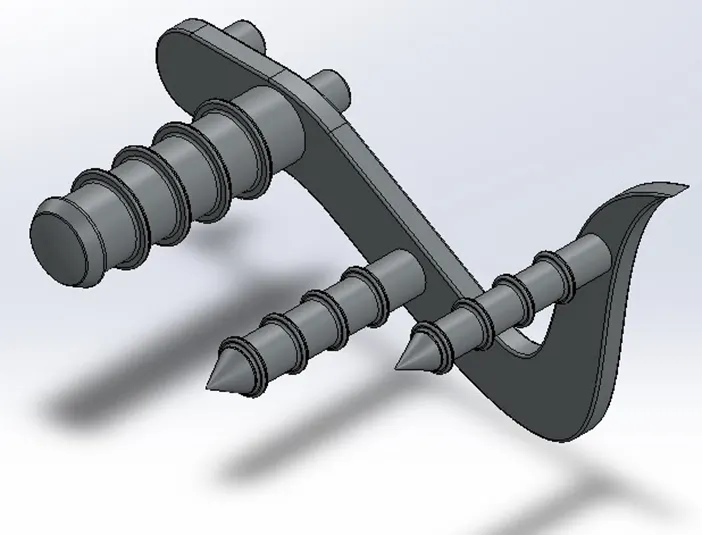
Fuel Tank with seat
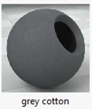
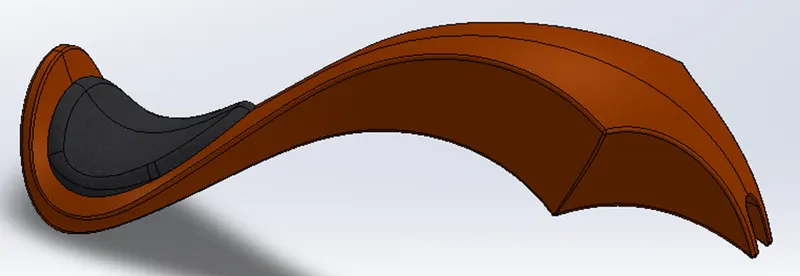
The appearance given to the Fuel Tank is Siena and to the Seat is Grey Cotton.
ASSEMBLY OF AMERICAN CHOPPER
All the parts that were modelled are imported to assemble them. In assembly, the mate feature is most commonly used to locate and relate the parts with one another. Chassis is the main component that is inserted first and then fixed. The other components were inserted one by one and by using planes for reference and giving the mate feature once the part gets fixed it floats with the mainframe. Some parts were modified during assembly to make it perfect according to requirements.
Mates
 Mates create geometric relationships between assembly components. As you add mates, you define the allowable directions of linear or rotational motion of the components. You can move a component within its degrees of freedom, visualizing the assembly's behaviour.
The mates used in the assembly are
- Coincident Mate
- Distance Mate
- Concentric Mate
- Angle Mate
- Limit Angle Mate
- Width Mate
- Tangent Mate
Coincident Mate 
A Coincident mate, like the name sounds, is a mate between two features that you want to coincide with each other.
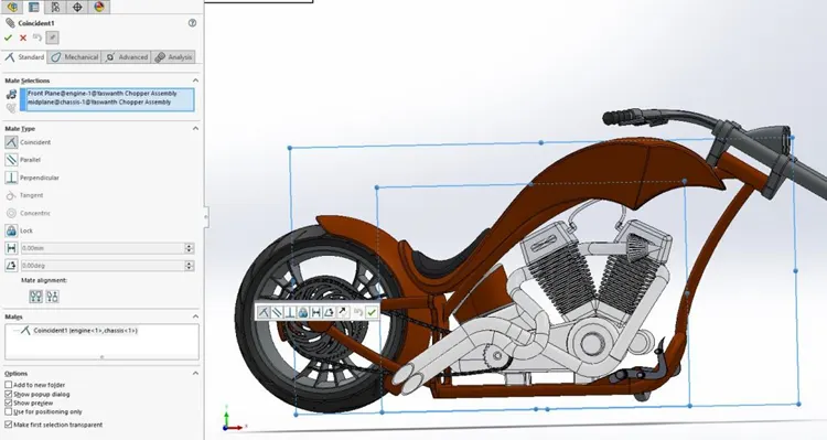
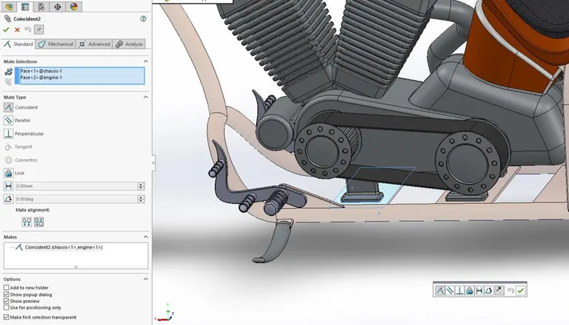
Coincident Mate between Planes Coincident Mate between Faces of Chassis and Engine
Distance Mate 
A Distance mate, like the name sounds, is a mate between two features that you want to coincide at a distance with each other.
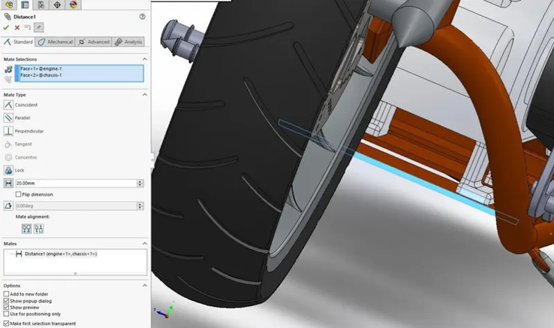
Distant Mate between Faces of Chassis and Engine
Concentric Mate 
A Concentric mate, like the name sounds, is a mate between two features that you want to coincide by joining the two centre points of two different spherical or conical faces.
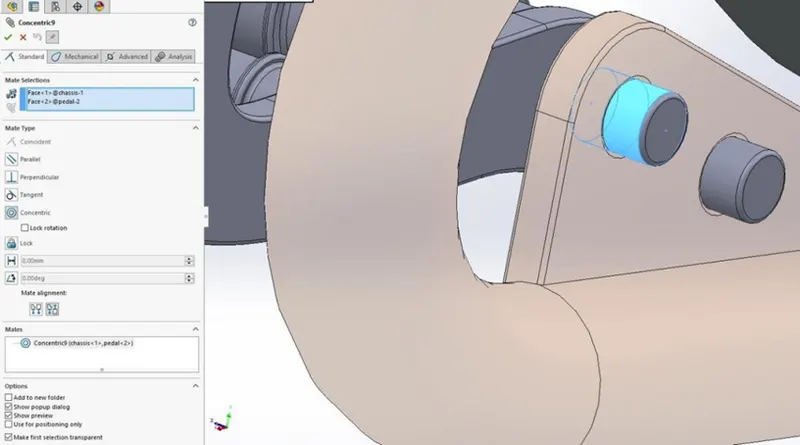
Concentric Mate between Faces of Pedal and Chassis
Angle Mate 
An Angle mate, like the name sounds, is a mate between two features that you want to coincide by a fixed angle between the faces.
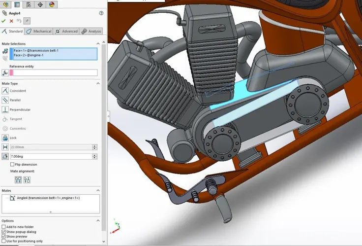
Angle Mate between Faces of Transmission Belt and Engine
Limit Angle Mate 
A Limit Angle mate, like the name sounds, is a mate between two features that you want to allow the movement of the component within the set angle between the faces.
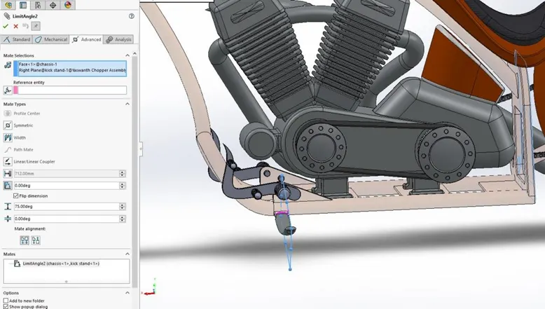
Limit Angle Mate between Kickstand and Chassis
Width Mate 
A Width mate, like the name sounds, is a mate between two features that you want to centre between the tabs of the faces of a component.
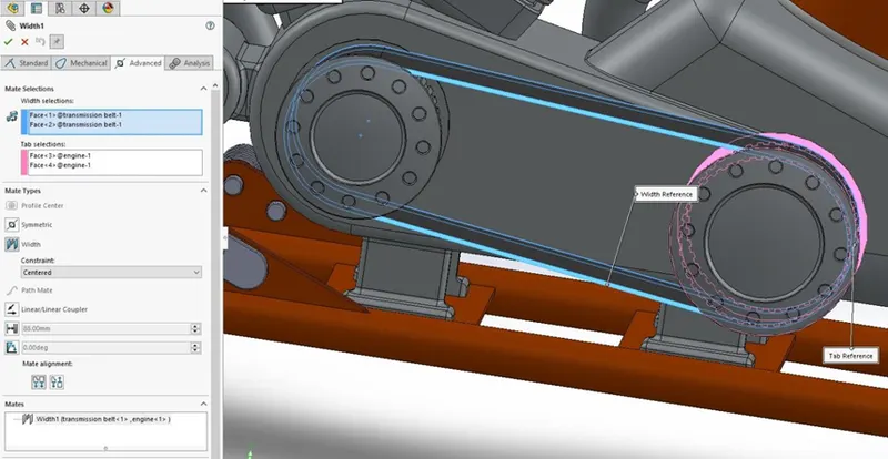
Width Mate of Faces between Transmission Belt and Engine
Tangent Mate 
A Tangent mate, like the name sounds, is a mate between two features that you want to coincide the faces between two components.
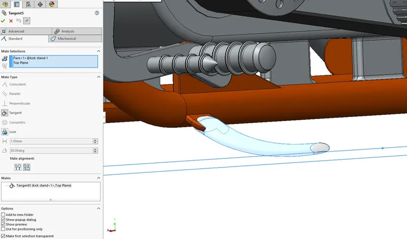
Tangent Mate between Kickstand and Top Plane
The result obtained after applying required mates is
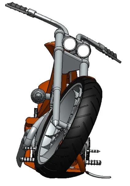
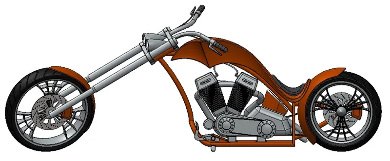
Front view Side view
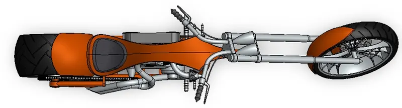
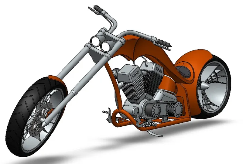
Top view Isometric view
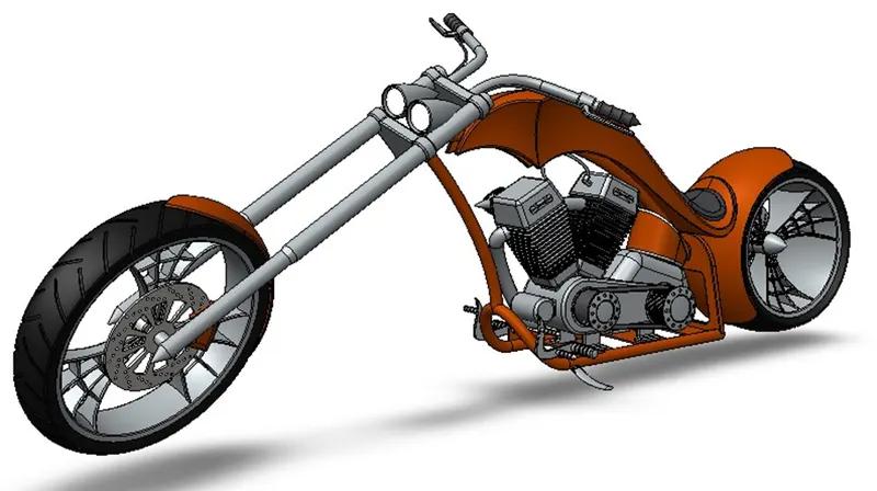
Camera scene view
Decals
A decal is something called a “transfer”, and it consists of a picture, image, pattern, or design that’s printed on a metal body. We have added decals on the Fuel tank, Rear fender and Oil tank of the chopper. It gives a nice appearance to the chopper.
Fuel Tank
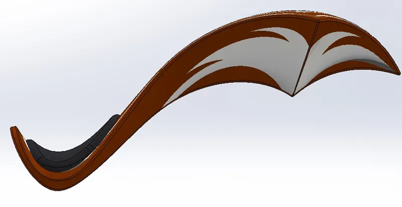
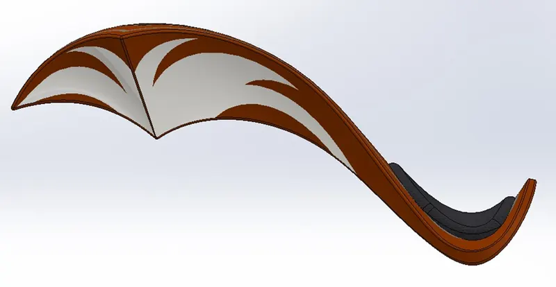
Fuel Tank Right Side view Fuel Tank Left Side view
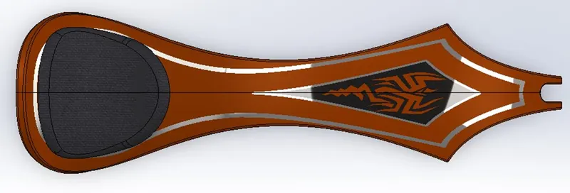
Fuel Tank Top Side view
Rear Fender
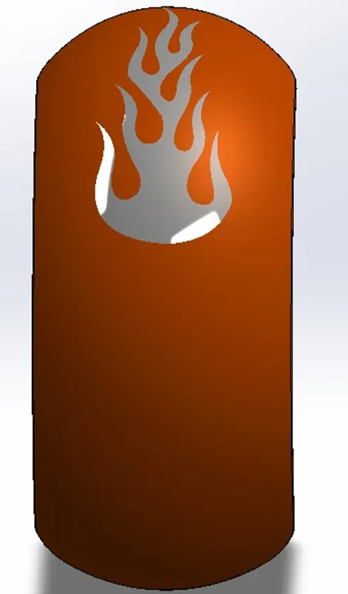
Rear Fender Front view
Oil Tank
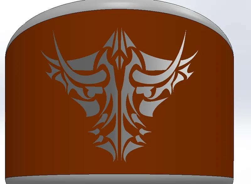
Oil Tank Front view
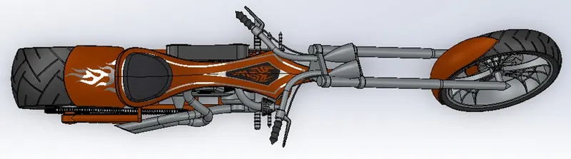
The final result after applying the desired decals on the AMERICAN CHOPPER is displayed below.
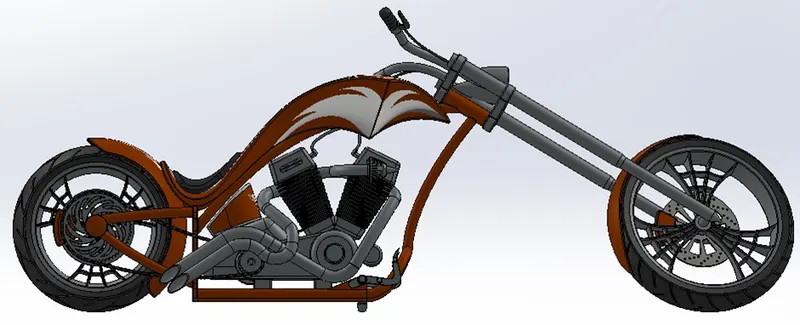
Chopper Right side view
Chopper Top view
RENDERING
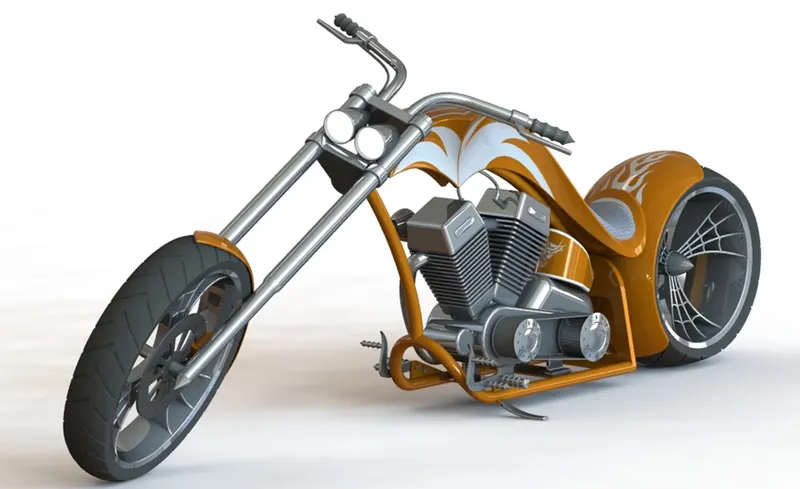
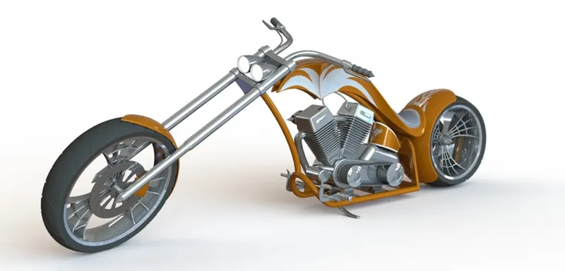
The term rendering comes from the graphic world where a rendering is an artistic drawing of what a new structure would look like. In Computer-Aided Design (CAD), a rendering is a particular view of a realistic image. By doing a rendering of a chopper, we get the idea that how it will look into the environment. This rendering is done in the SOLIDWORKS Visualize software. By using PHOTOVIEW 360 we can add various camera views to the model, we can set various angles, directions, and can set appropriate distances to get the perfect camera view. In rendering, we change the colour of chopper parts, background images, brightness, rotation and various setting of the chopper. Including the resolution and a set number of passes, we get more detailed visuals of the chopper.
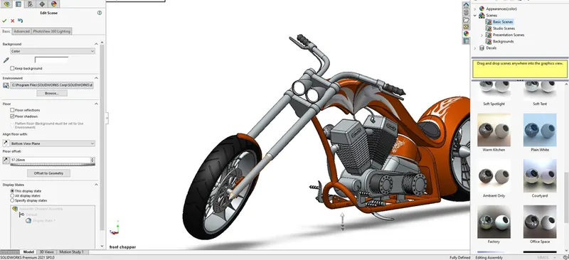
Render Scene Setup
For rendering the chopper, we need to create an environment virtually where the chopper is placed with the desired location, lights and scenes. So we are going to use one of the basic scenes called Plane White in this report.
Rendering scene creation
Camera Setup
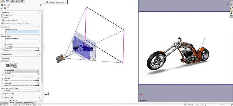
The Camera setup is an option used for setting up the view of the object with our required lighting, angles, length, height, image aspect ratio and depth field to avoid any distortions during the final rendering of the chopper.
While creating the camera setup
Final Render 
The Final Render option creates the chopper using all the processing power of the computer (both CPU and GPU) for creating a realistic image in the SOLIDWORKS utilizing Photoview360.
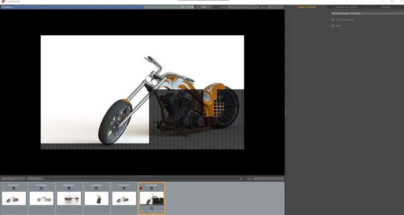
During Final Rendering Process
CONCLUSION
To conclude in this report, the AMERICAN CHOPPER bike can be sketched, modelled, designed and assembled at a component level and rendered photo-realistically using SOLIDWORKS and Photoview360.
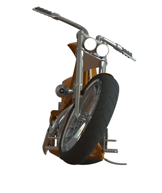
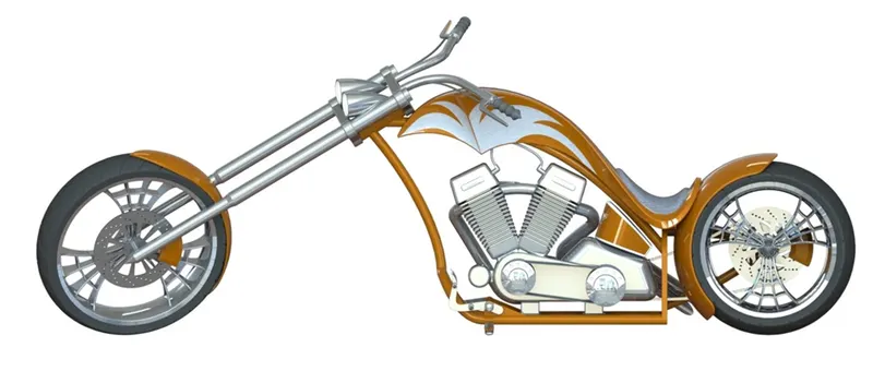
Front view Side view
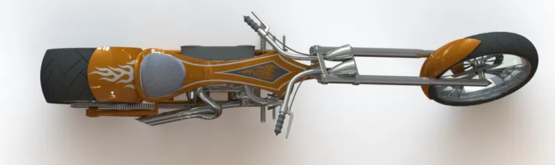
Top view Isometric view
Camera scene view