Week 9 - Project - A pillar Design with Master Section
A PILLAR DESIGN WITH MASTER SECTION
- MASTER SECTION
Given for the reference of Class A, Class B and Class C surface.
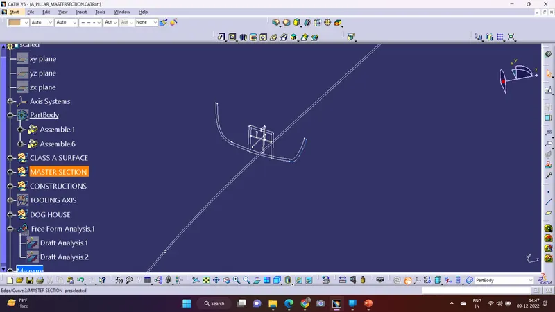
Class A Surface
Before we start working on our class B surface we should always check our Class A surface that it's a single component or not, we should make sure that there is no missing pieces or any non - connectivity in the Class A surface.
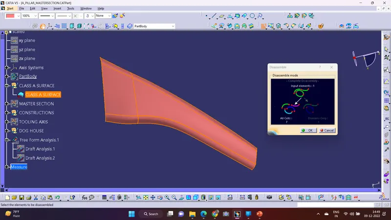
As we can see that our Class A surface is proper.
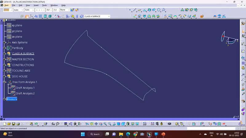
We can also check for the missing patches with the boundary also, as you can in the bellow image,
TOOLING AXIS
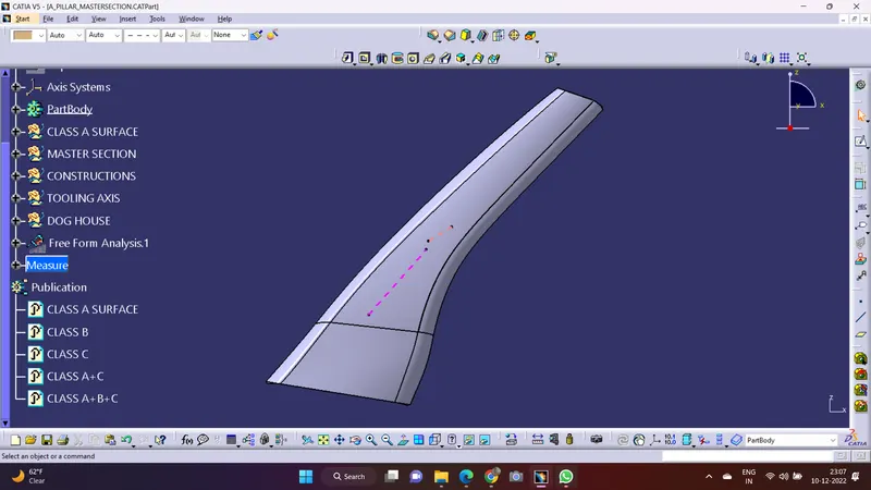
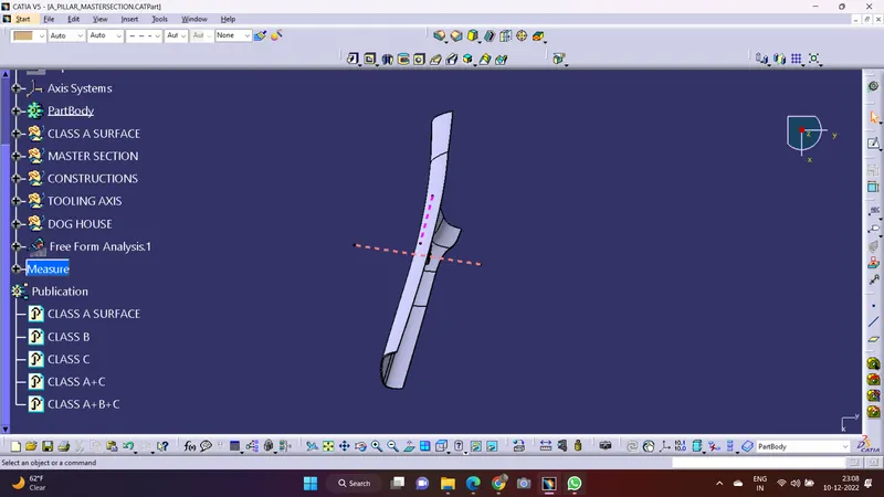
In this challenge for creating the tooling axis we'll use a different method for it like we'll take the reference from master section for creating the tooling axis,
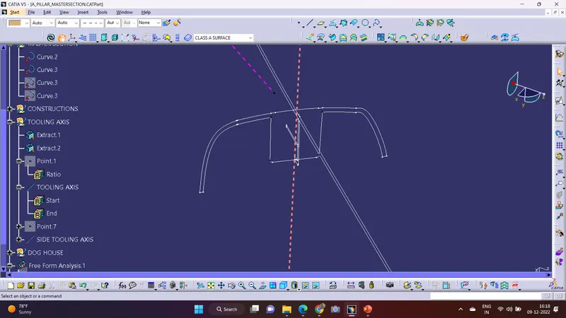
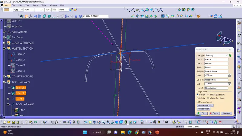
After that we'll create a mid point by using those extract for the reference of creating a bisecting line, after that we can easily create a bisecting line with all of this references, as you can see in the below image.
DRAFT ANALYSIS FOR CLASS A
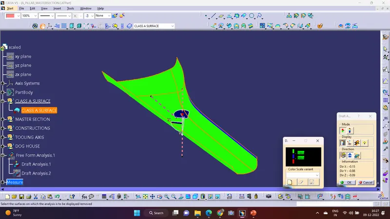
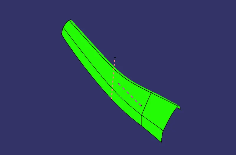
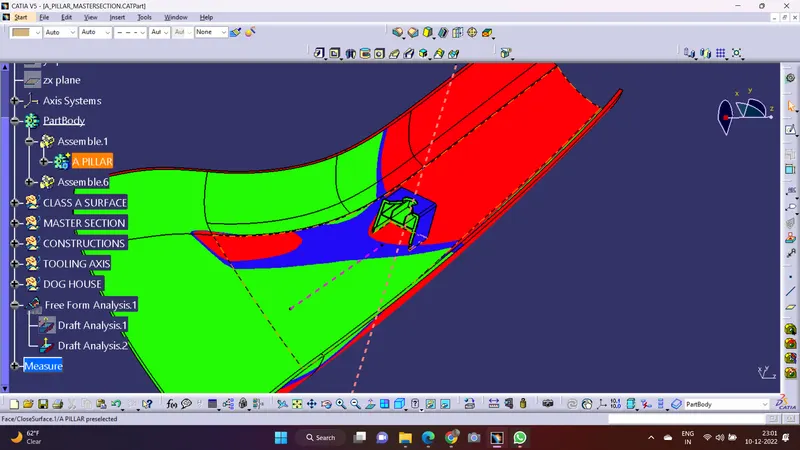
After creating the main tooling axis we can easily, chack the draft analysis for the class A surface and after that we can easily determine that our tooling axis is properly created or not and if not than we have to recreate our tooling axis according to it,
CLASS B SURFACE
For creating the class B for A pillar we'll use the offset option, so we'll offset the surface from Class A surface for creating class B the offset will be 2.5mm,
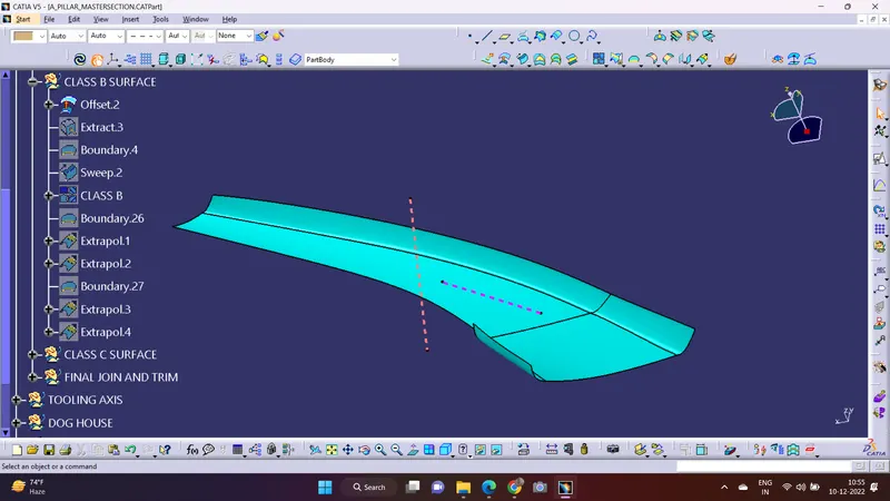
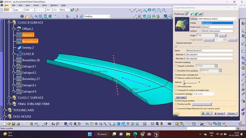
As we can see in the above image, there is a patch missing in it and the patch that is missing is a curved patch and we don't have that many options to create this patch cause we only have 2 support that we can take so for this one we can't use multi section surface, the only thing in creating this surface we can use is sweep command for it, so in the sweep command we'll use with reference surface, cause in that we'll need a profile and one guide curve for creating the profile
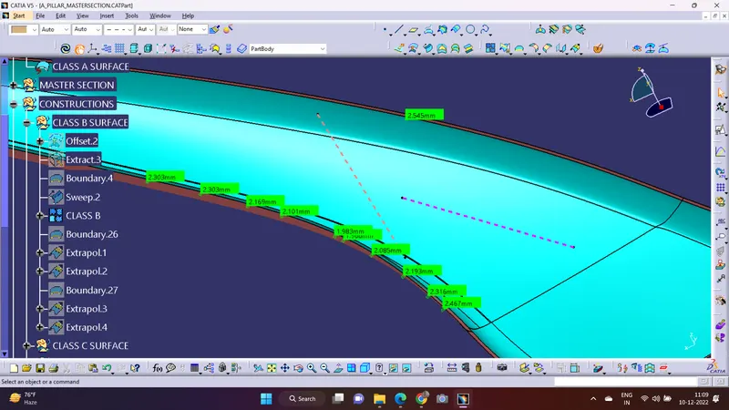
After creating the sweep we seen that there is a diffrence between our thickness in the Class A and Class B surface, actually there's a varition in the thickness of the component the thickness varition is between 0.6mm ( and I have talked about this with our skill lync support engineer they told me that it is because of the Class A surface), and as we know we can't actually do any changes in the class A surface, so for that we'llhave to report to the Class A engineer for this so he can make the changes in the Class A surface, so for now for the challenge we'll have to work with that variation in it ,
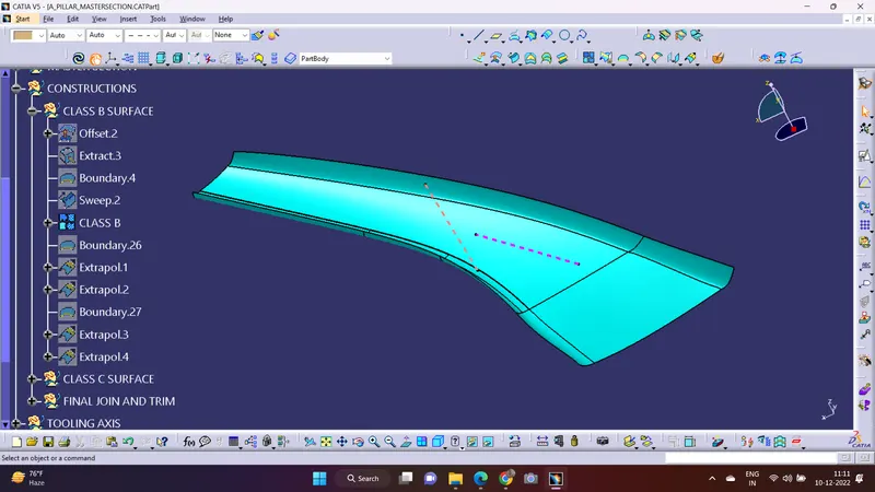
After creating the B surface we can start working on Class C surface,
CREATION OF CLASS C SURFACE
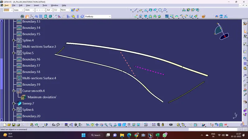
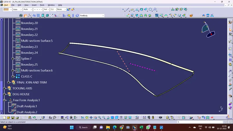
For Creating Class c surface we need to use sweep command for screating Class C surface, In creating Class C surface we have to create the sweep command separately and in the patches were we can't use sweep to create Class C, for that we are gonna use a different approach for that, we're gonna use multi section surface command for creating that patch were sweep is not gonna work, after doing all that we are gonna join all the sweep and multi section surface as the output we'll get out Class C surface,
FINAL JOIN AND TRIMS
After creating Class C surface we'll join our Class A and Class C surface together to get a single component after that we'll trim Class A & C surface with Class B surface to get our required component
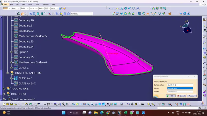
then we'll trim the Class A & B with C suface to get a single component,
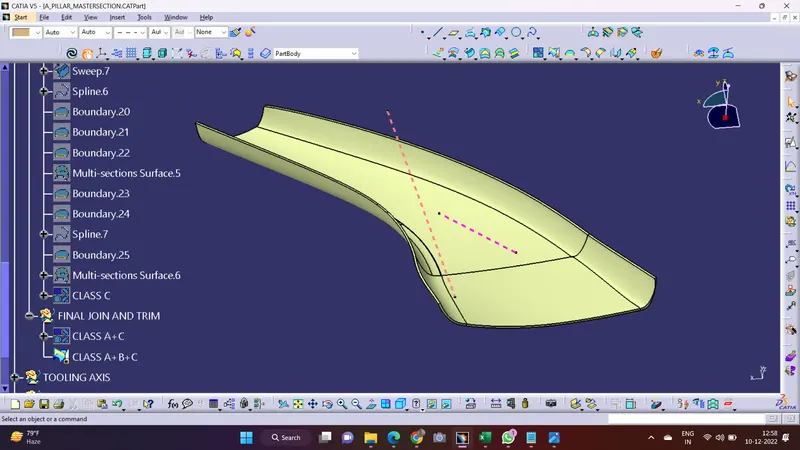
After creating all this we can create our solid body from this by using close surface command to create solid body from it,
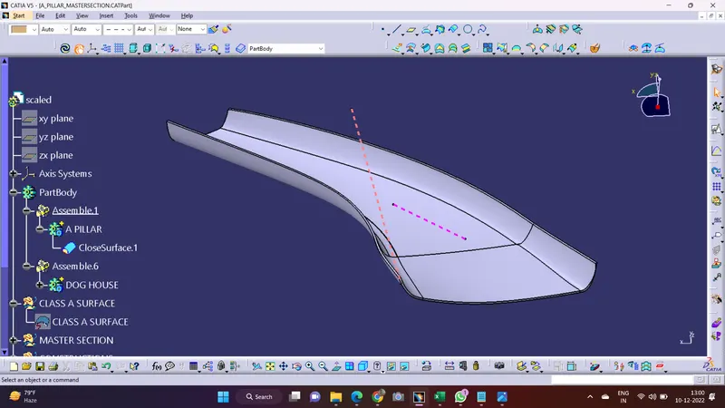
CREATION OF DOG HOUSE
Now we'll create the dog house from the master section that has been provided to us with the help of the master section we'll create our sketch of dog house, by doing that we don't have to give the draft to the outer part of the dog house or use sweep command for it, we'll simply just use extrude command for it,
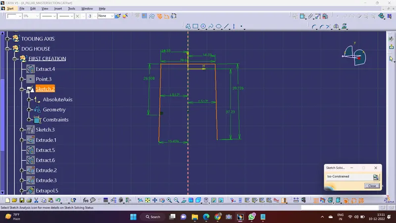
After working with the above image we'll simply just extrude our component and work with it
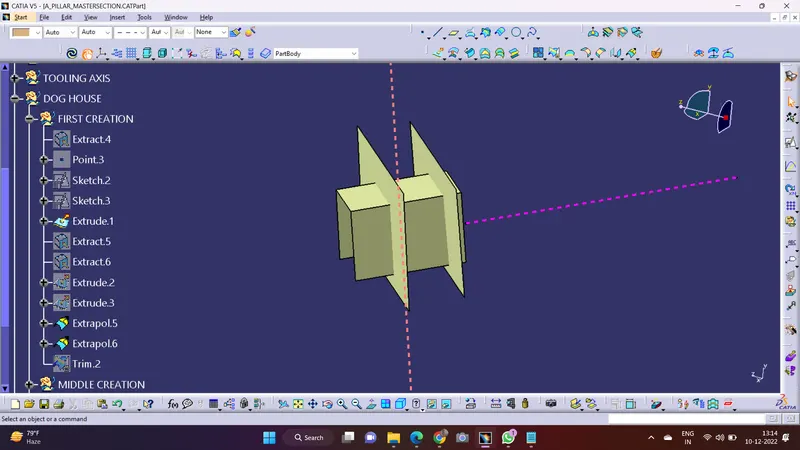
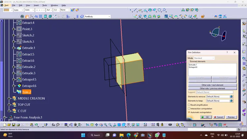
After performing trim we can use the thick surface command to thicken the body and use the split command to cut off the extra part that has been extruded with the help of split,
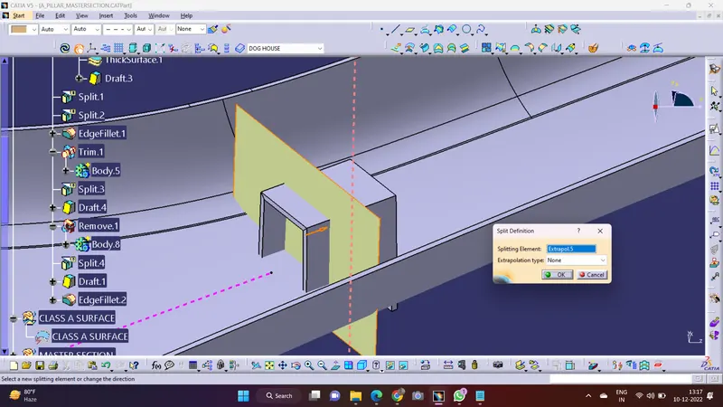
And then we'll fillet the outer surface according to the master surface and then we will again use the split command to cut the extra part according to the requirements but in this case we'll use the Class A surface for performing split command,
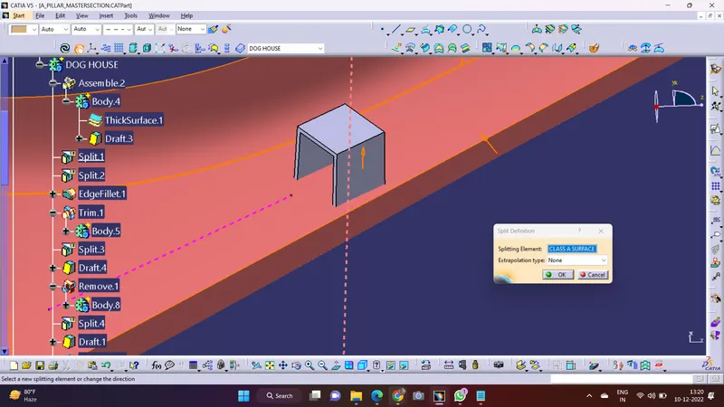
After that we will create the middle part as to the requirement of the master section that has been given for the refrence as sown is the below image, and as According to the master section the thickness of the RIB in the middle of the thickness is 1mm and we'll take the placement of them according to the master section,
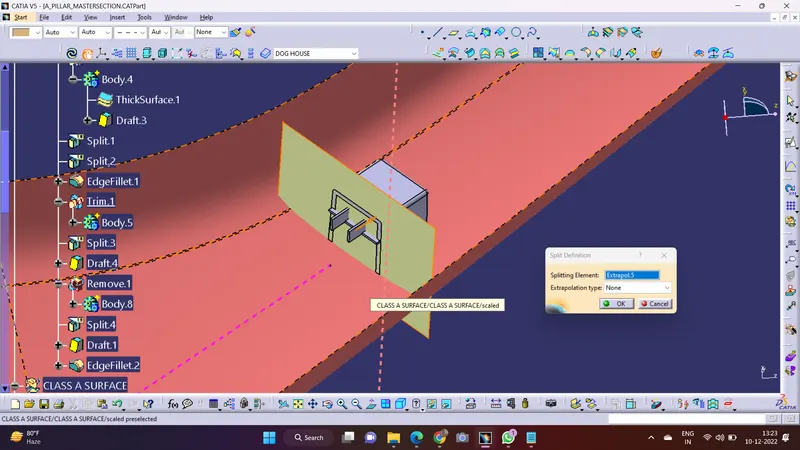
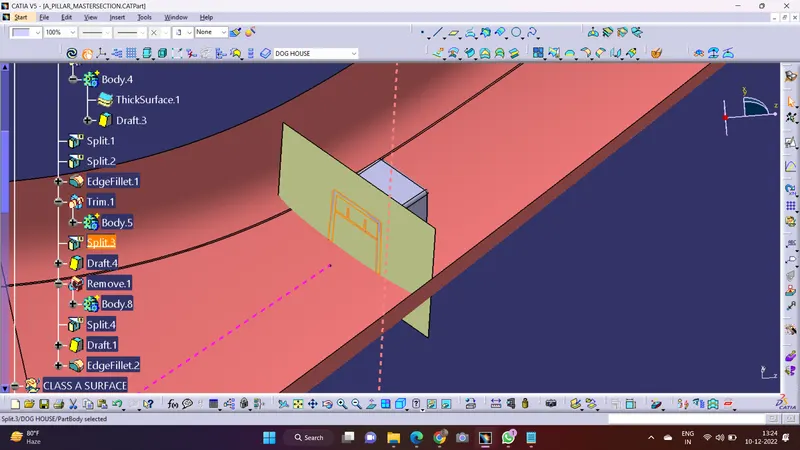
After that we'll create the cutout in the top of the dog house by using boolean features,
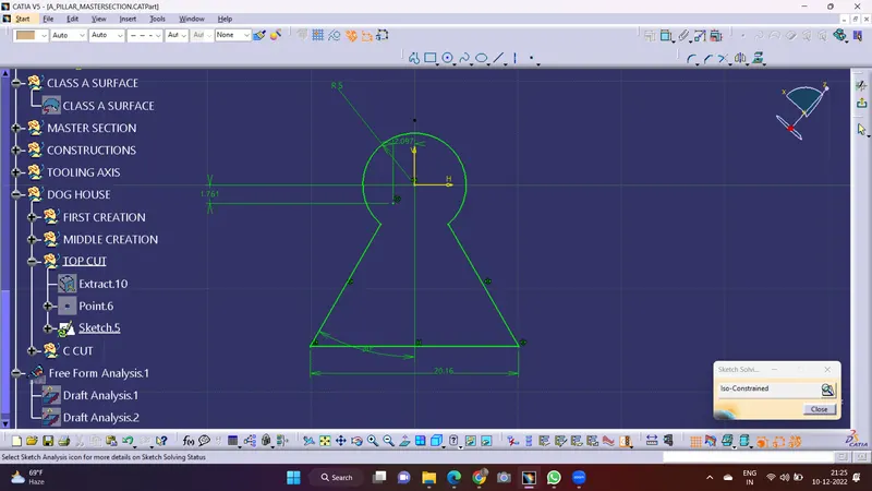
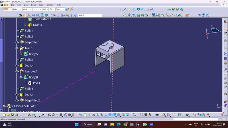
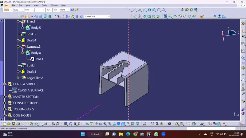
After that we'll make the cutout at the end of the dog house to avoid the sink mark, and for the we'll follow the design rules that are, the thickness of the cut should be 40% of the thickness of the dog house and the of that should be between 3-6mm, so we'll create our extraction according to that only,
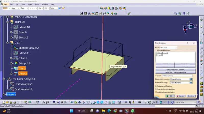
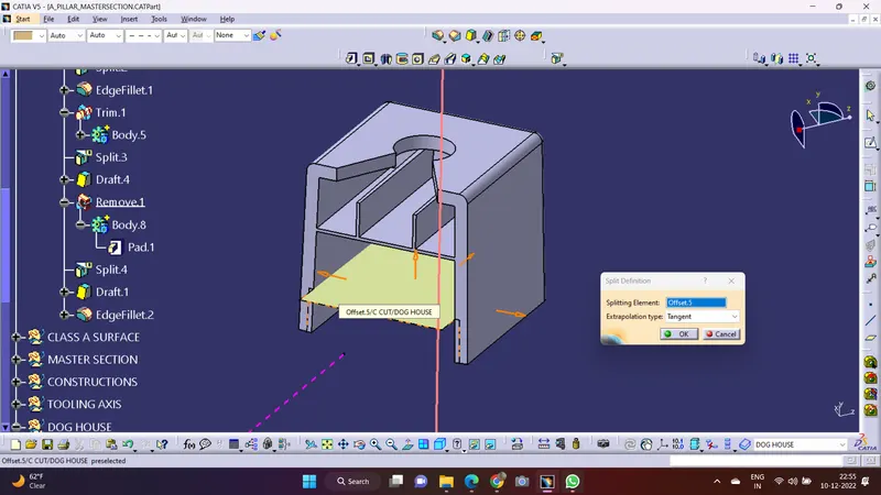
After that just provide the fillets to the ribs to all the body according to the master section,
DRAFT ANALYSIS FOR SOLID BODY
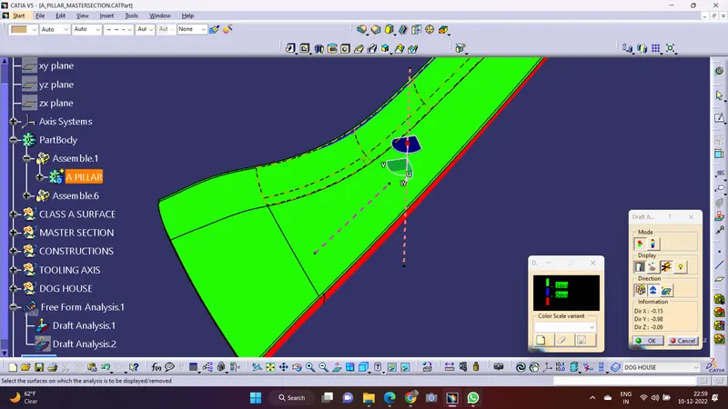
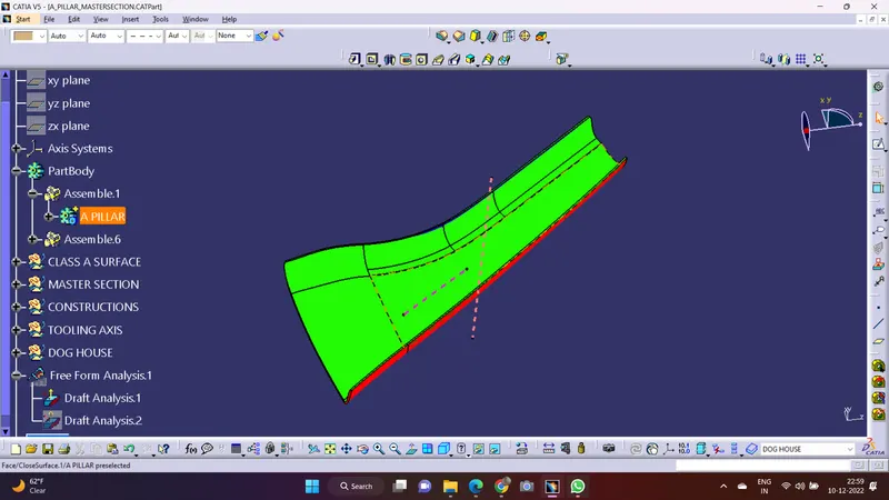
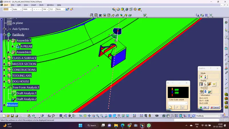
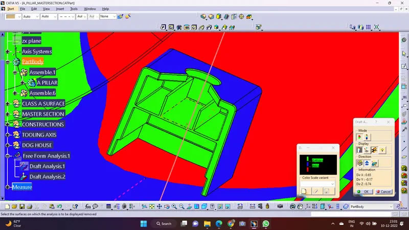
For dog house change the draft angle to 1.45 degree,
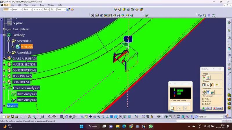
And for the inside draft analysis we have to change the tooling axis from main tooling axis to side core tooling axis and the angle to 0.45 degree, we can given the draft as 0.5 degree but when we do the draft analysis we have to give Clarence also that's why give the drafting angle as 0.45 degree,
VIEWS
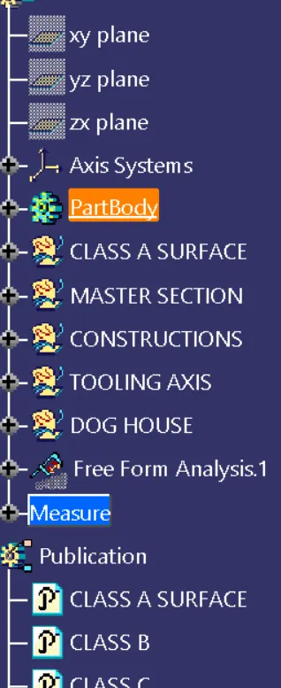
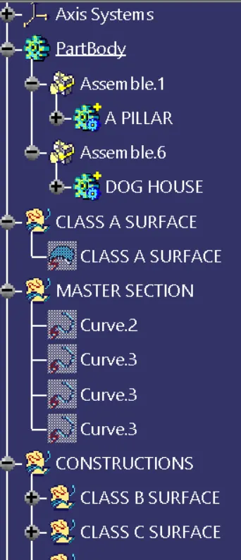
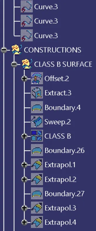
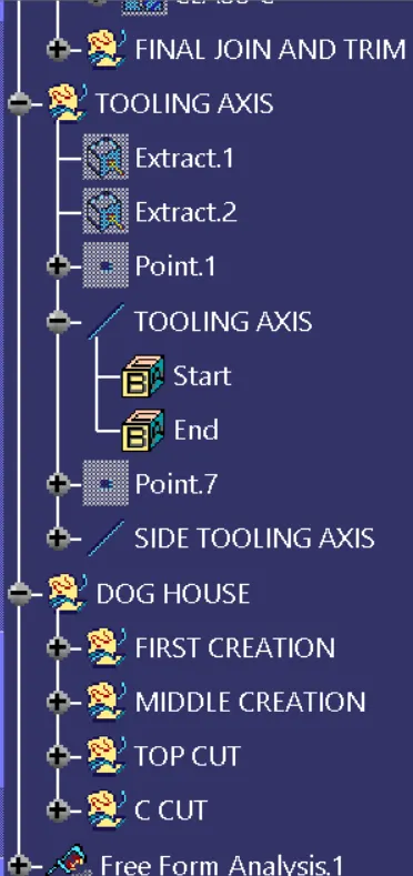
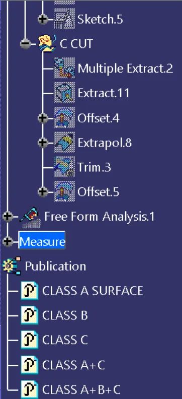
TREE STRUCTURE