Week 9 - Project - A pillar Design with Master Section
A-PILLAR DESIGN WITH MASTER SECTION:
AIM: To design "A-PILLAR" solid model using the given Class A surface and Master section, and then create the Dog House with ribs following the design rules.
GIVEN INPUTS:
The Class A surface of A-Pillar and its Master Section are given as inputs for design of Class B and C surfaces.
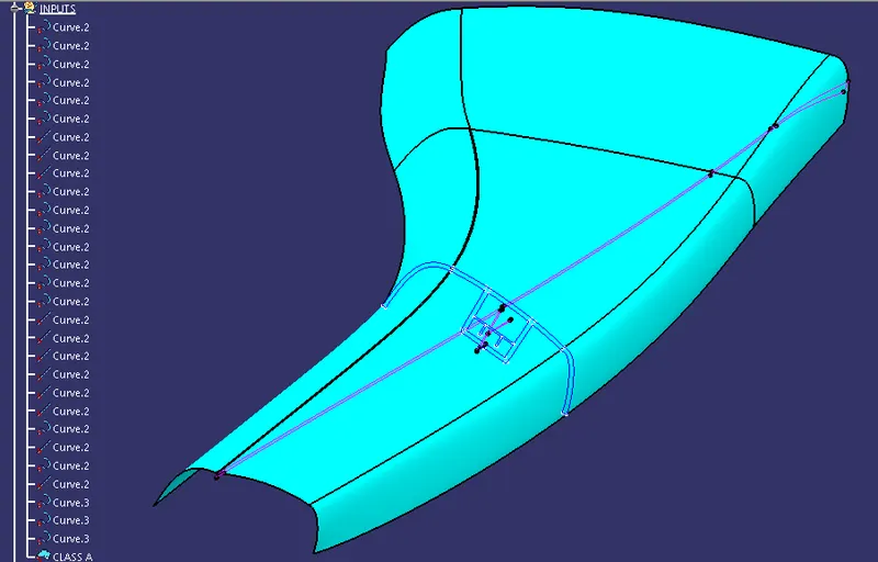
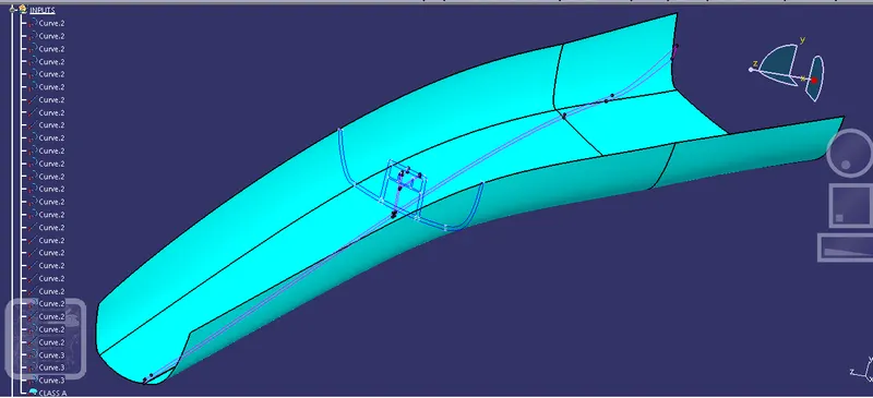
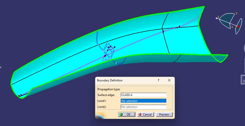
The quality of the surface is checked using the Boundary command to find any open edges.
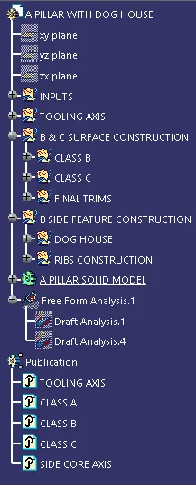
EXPANDED TREE STRUCTURE:
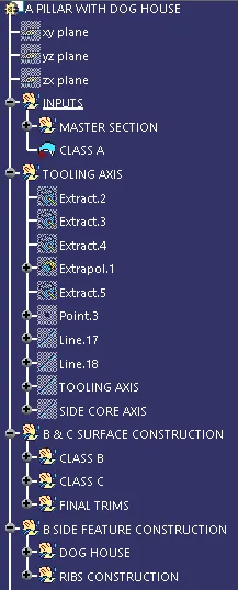
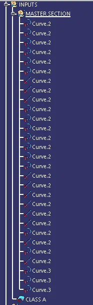
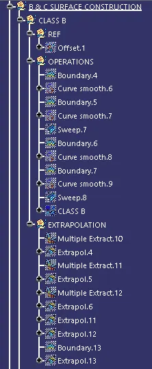
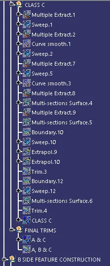
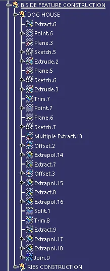
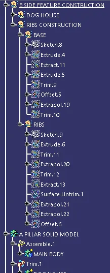
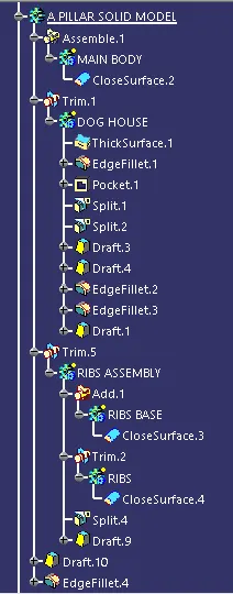
TOOLING AXIS CREATION:
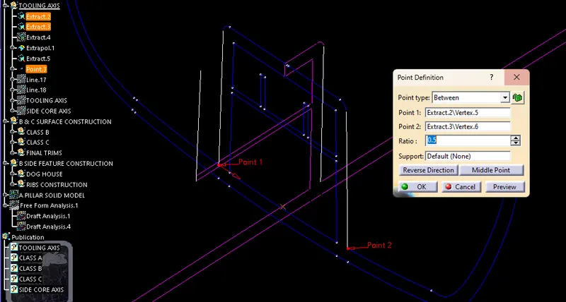
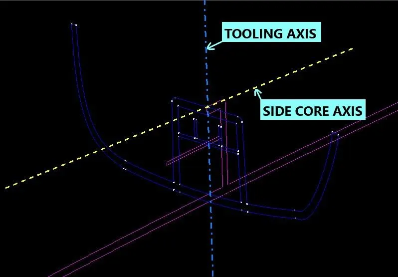
Tooling axis is created using the Bisecting Method. For the given master section, the axis can be created at the geometrical centre of the Dog House. The outer edges of the Dog House from the master section are extracted and extrapolated as shown in the below image.
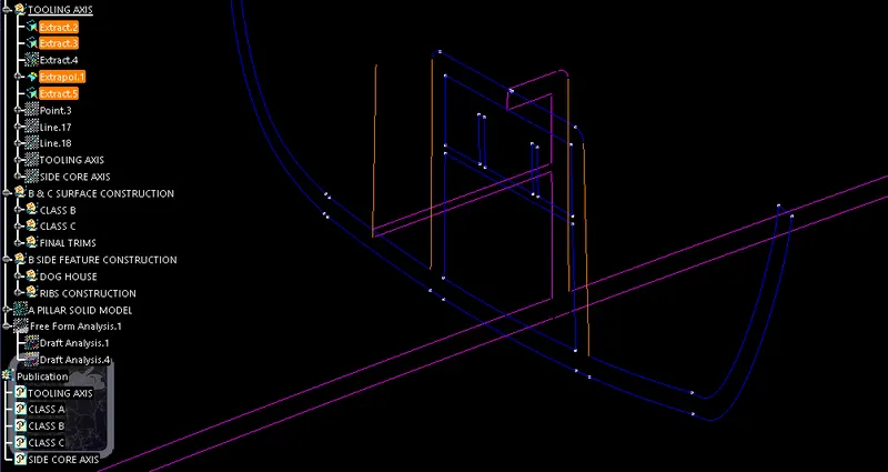
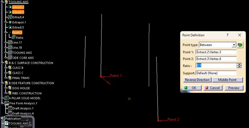
A point in the middle is created between two opposite extracted edges as shown below.
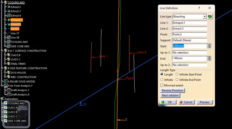
Now, a line bisecting the other two opposite edges is created with the point as input as shown in the image below.
Similarly another bisecting line for the first two opposite edges is created giving the same point as input.
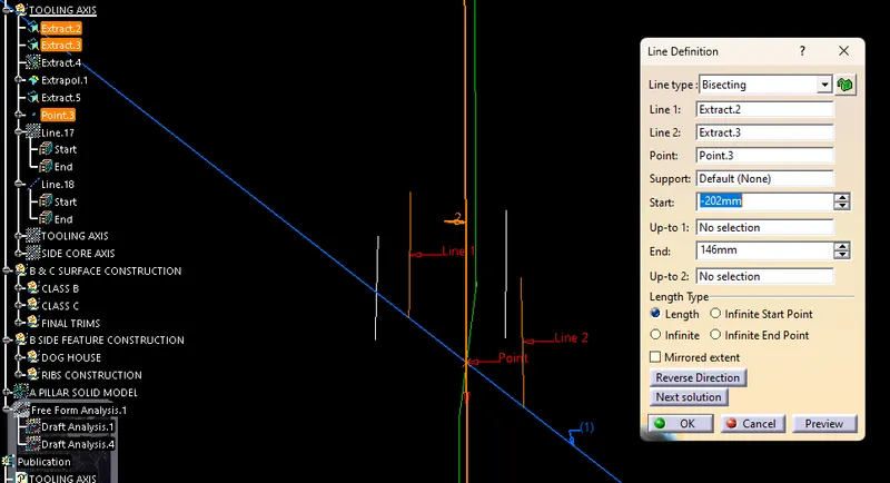
Now the main tooling axis is created by bisecting the two lines and giving the point as input.
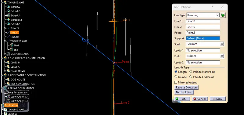
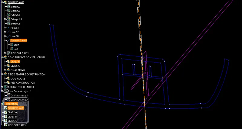
The line is renamed as the Tooling axis and published for easy access.
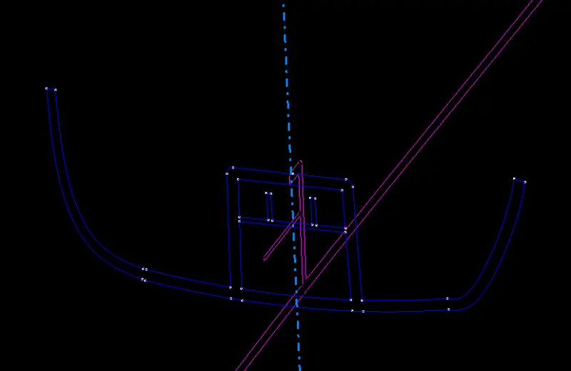
SIDE CORE AXIS:
For the Dog House, a Side Core or Lifter axis is also created for providing draft to the inner walls of the Dog House. It is created by taking a plane parallel to the master section and constructing a line normal to the plane passing through the mid vertex of the upper edge in master section as shown below.
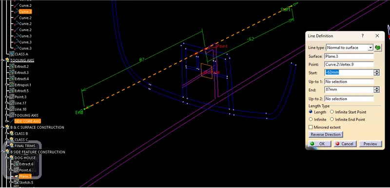
It is renamed as Side Core axis and published for for easy access.
CLASS A DRAFT ANALYSIS:
Draft Analysis is performed on the Class A surface after creating the Tooling Axis. It is performed to check if the surface clears the tooling. The compass is used to define the current draft direction. It is aligned with the Tooling Axis to define the draft direction and the surface is selected to perform the analysis.
The results of the draft analysis are show in the below pictures:
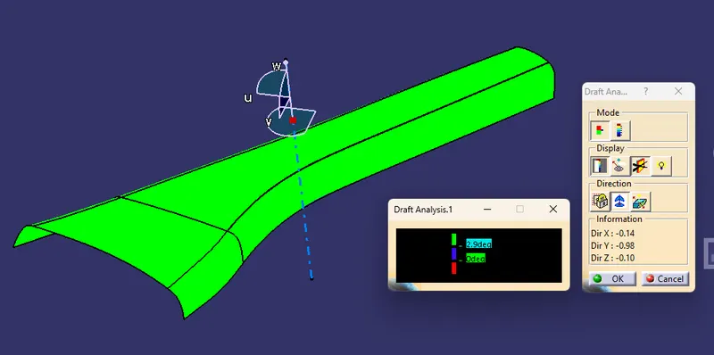
For a draft angle of 3 degrees, the surface clears tooling for the maximum area except for a small patch where the minimum draft is 2.7 degrees which is feasible.
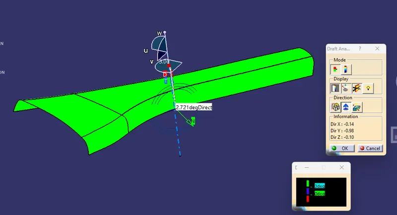
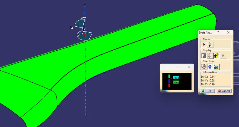
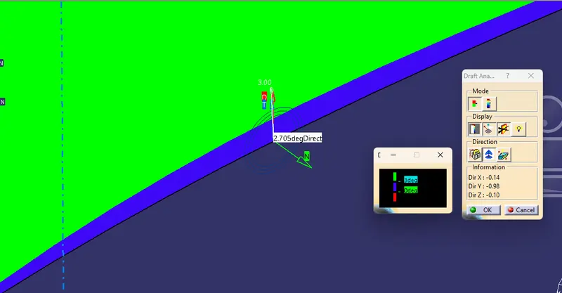
From the results obtained, we can see that the Class A surface is drafted properly with very little deviation. Hence the tooling axis created is feasible and the surface is good to go.
CLASS B & C CONSTRUCTION:
CLASS B:
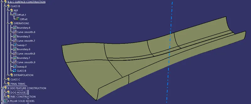
From the given master section, we can observe that the part thickness is 2.5mm. So the Class A surface is offseted for 2.5mm and Class B surface is created. The missing patches in the offset are constructed using the tools availabe in the surface workbench. The operations used for the construction are Boundary, Curve Smooth and Sweep. Then the patches created are joined with the offset using the Join command to form the required Class B surface.
CLASS C:
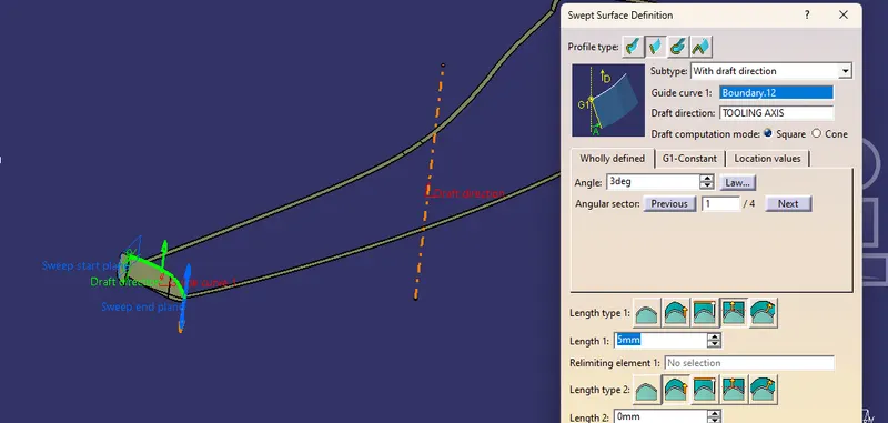
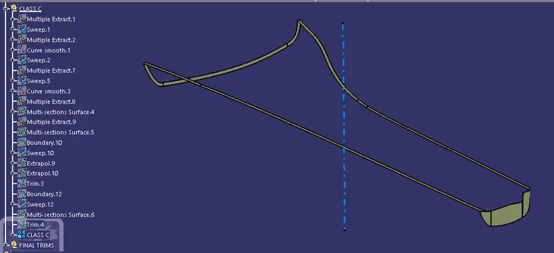
Class C surface is also created using tools like sweep, multi-section surface, extrapolate, trim, etc. While using the sweep tool, an angle of 3 degrees draft with respect to tooling direction is given as shown below:
After creating the individual sweeps, all the surfaces are joined to form the required Class C surface as shown below:
Then, the Class A, B & C surfaces are extrapolated and trimmed together to form a closed surface with no open boundaries.
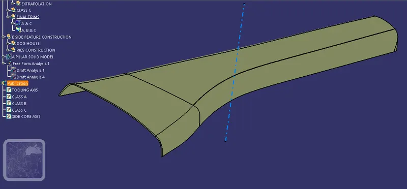
SOLID BODY:
The Closed Surface is made into a solid model using the close surface tool in Part Design workbench.
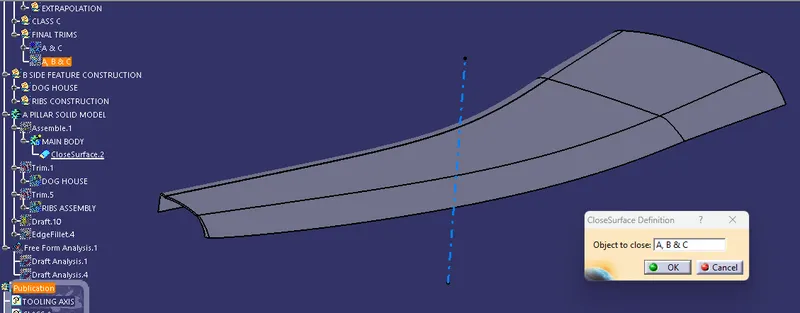
ATTACHMENT FEATURE CONSTRUCTION:
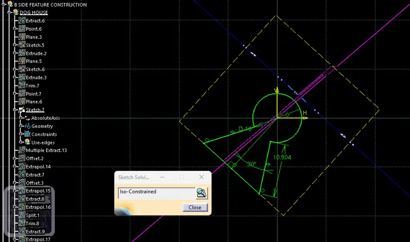
After creating the solid model, the attachment features are constructed on the Class B surface using the master section and following the design rules for construction of engineering features. The 2D sketches used for the creation of Dog House with their sketch solving status are given below:
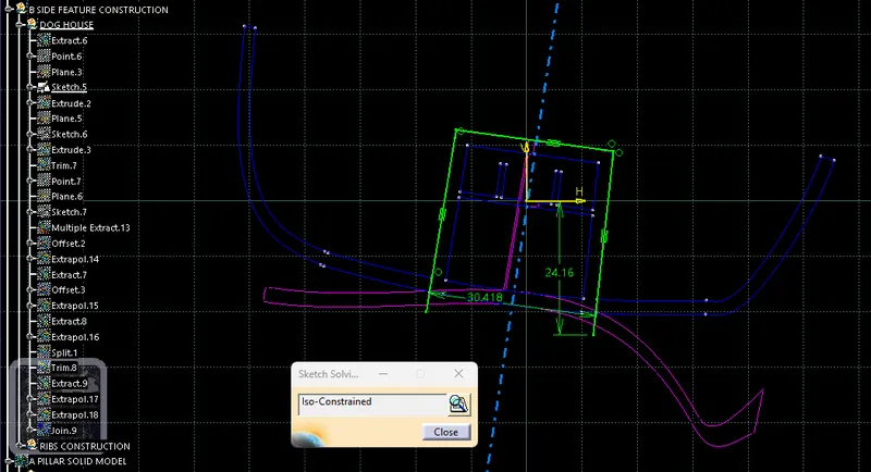
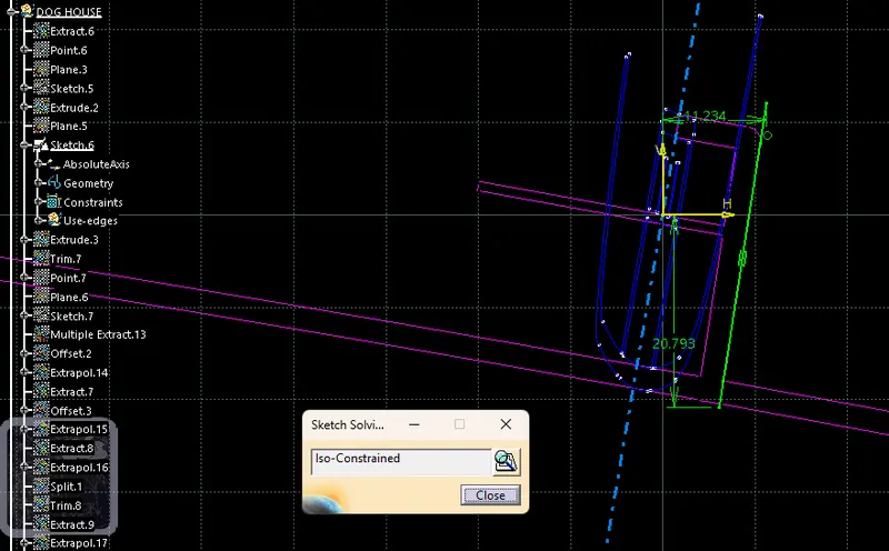
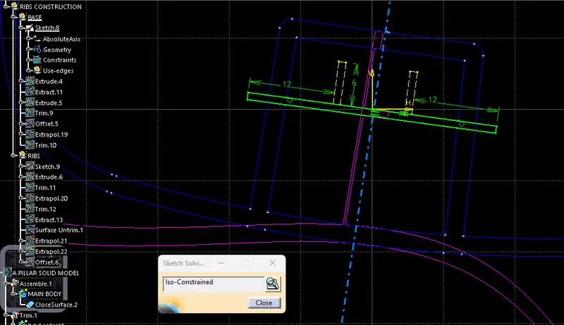
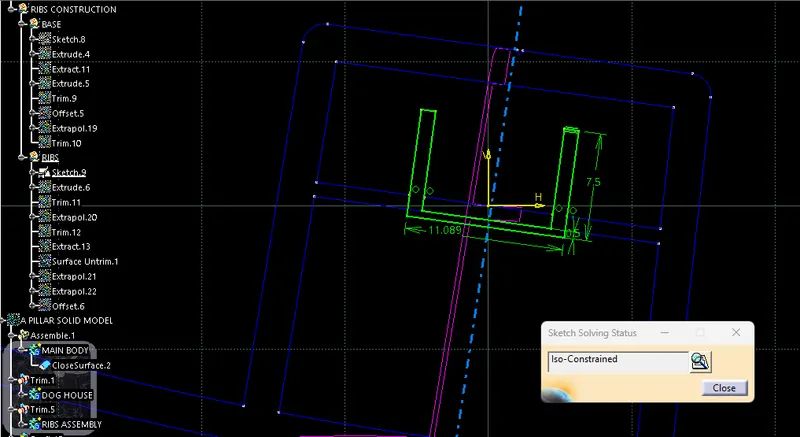
The 2D sketches used for the creation of Ribs inside the Dog House with their sketch solving status are given below:
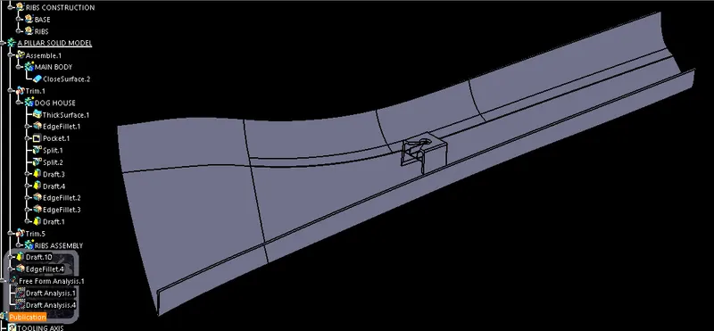
The Dog House along with the ribs thus created using the sketches and other operations are union trimmed to the main body to form the final required solid body.
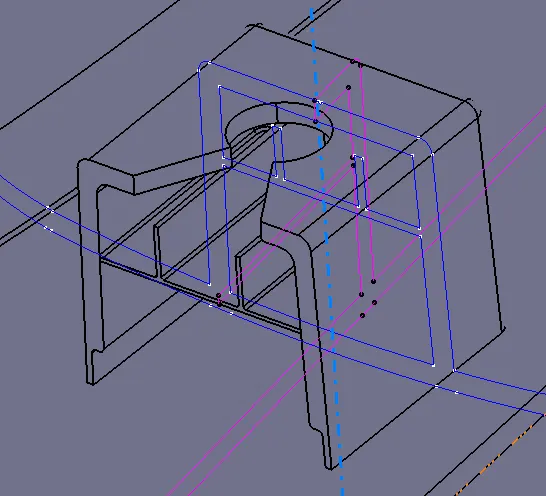
The outside walls of the Dog House are drafted with an angle of 0.5 degrees with respect to the main tooling axis. The result for the analysis is shown below:
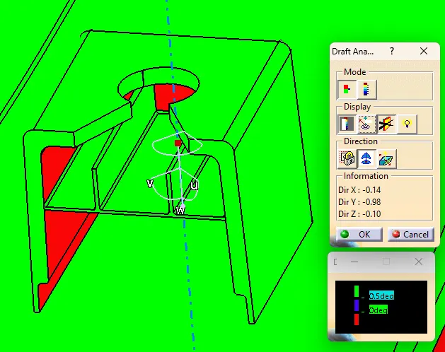
It can be seen that, the outside walls of the Dog House clears the minimum Draft of 0.5 degrees with the tooling axis as the color grade is green for the outer surface.
The inside walls of the Dog House are drafted with an anle of 0.5 degrees using the side core axis. The results of the draft analysis for Dog House with respect to side core axis are shown below:
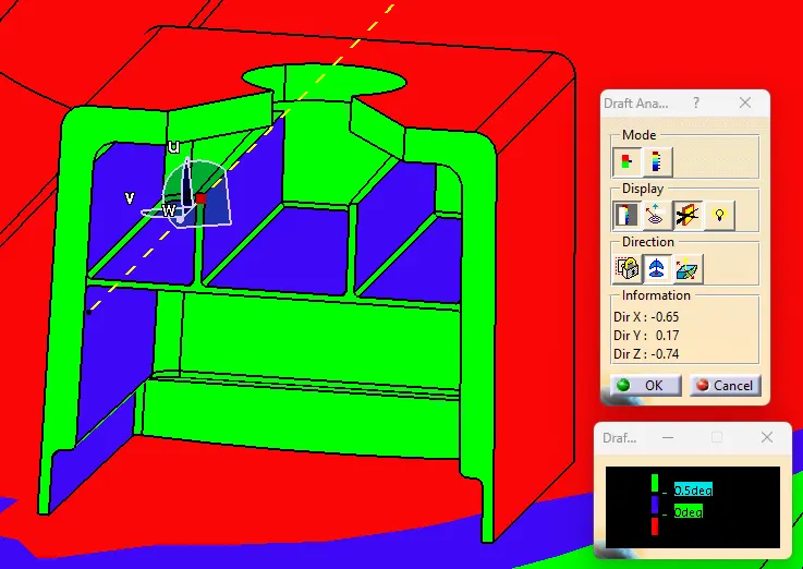
From the analysis, we can see that for 0.5 degrees, the color grades seen inside the Dog House are blue and green which indicates that it is drafted properly. For an angle of 0.49 degrees, the Dog House clears the draft completely with respect to the side core axis which is feasible considering slight deviation.
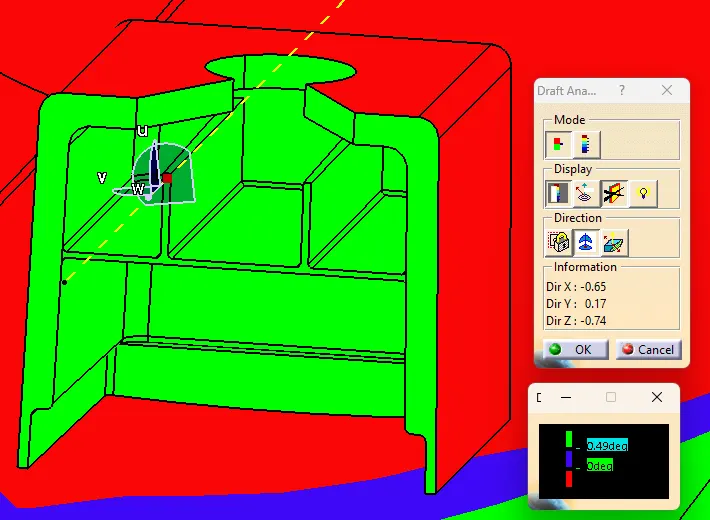
Hen from the results, it can be seen that the Dog House is drafted properly.
DRAFT ANALYSIS ON SOLID BODY:
Draft analysis is performed on the solid model and the results obtained are as shown below:
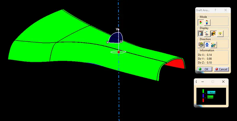
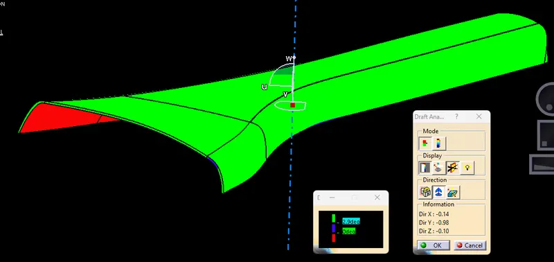
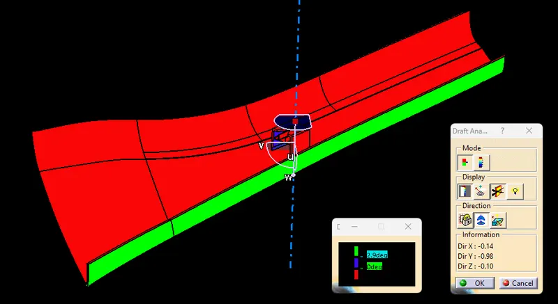
From the analysis, it is clear that minimum draft of 2.9deg is maintained for the Solid Model except for some areas.
VARIOUS ORIENTATIONS OF SOLID BODY:
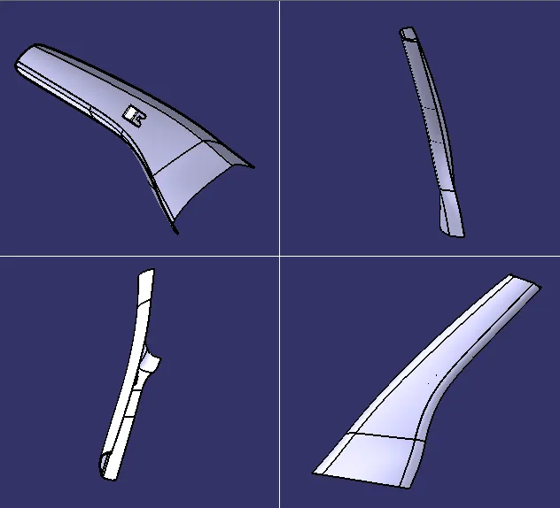
NOTE: A ppt on Draft Analysis of the entire solid body is attached along with the CAT part in the attachment below.