Week 8 - Challenge 1 - Base Bracket Design
BASE BRACKET DESIGN
AIM: To create the Base Bracket Plastic component through the given Class-A surface by creating a tooling axis meeting the requirements of the draft angle and to perform the Draft Analysis on the solid model at the end.
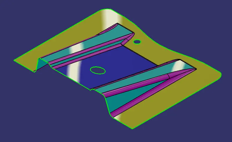
GIVEN CLASS A SURFACE:
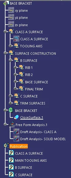
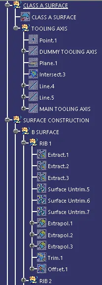
SCREENSHOTS OF EXPANDED TREE STRUCTURE:
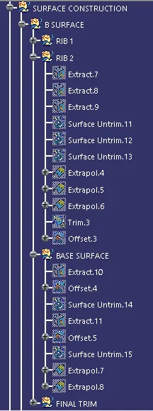
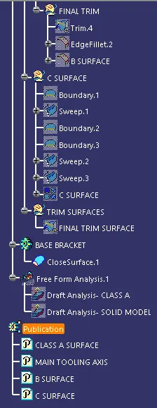
REPORT ON DRAFT ANALYSIS AND TOOLING AXIS CREATION:
DRAFT:
Draft angle is a taper applied to the vertical walls of the injection-molded component to assist with releasing the part from the mold. A functional part for injection molding has to have draft angles that face both the cavity and core sides. This will reduce the risk of damage to the parts and ensure that they can be ejected easily from the machine. A 3 degree angle is the most common draft provided in many components to minimize the warping of the geometry.
The Draft Analysis tool in CATIA allows the user to easily analyze a part for proper draft angle. This command enables us to detect if the part drafted will be easily removed. This type of analysis is performed based on color ranges identifying zones on the analyzed element where the deviation from the draft direction at any point, corresponds to specified values.
Creating a Tooling axis is the prerequisite for draft analysis.
TOOLING AXIS:
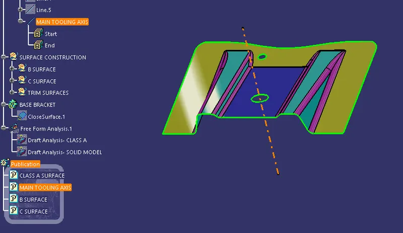
Tooling axis or Molding axis is the direction in which the core and cavity opens. It is basically the direction that the mold pulls apart. Creating a tooling axis is necessary to provide draft angle and analyze them. The tooling axis is created using Bisecting method.
BISECTING METHOD:
To decide the Tooling axis, it is made sure that the component is clearing the tooling axis in the given specific direction. The first step is to visually check the component for the best tooling direction in all three x, y and z directions. In the given Class A surface it is found that the best tooling direction is Z axis as the holes present on the surface cannot be cleared in either X or Y directions with minimum tooling. So Z direction is chosen for Tooling axis.
After the selection of direction, a dummy tooling axis is created in that direction for reference.
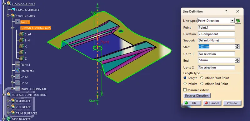
Then we select the surfaces near the axis that can probably create a problem to clear the tooling (surfaces that are most likely parallel to the axis) and take their intersections using a plane. These intersections are then exteneded using lines connecting their vertices.
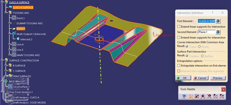
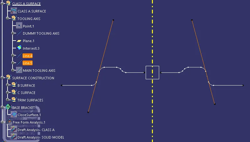
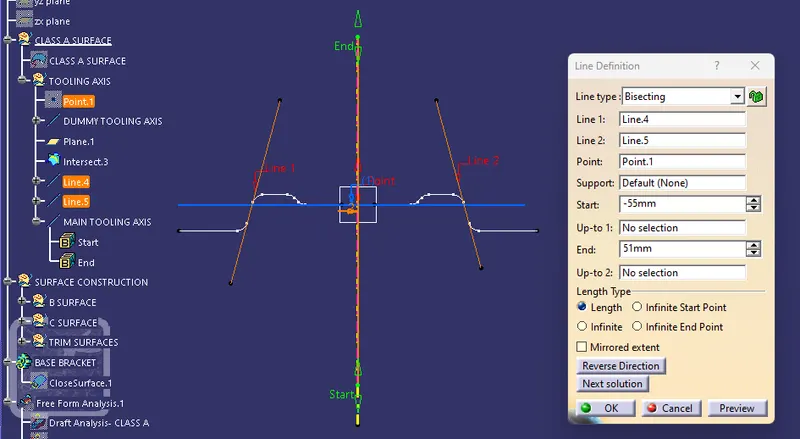
Then an another line of the type Bisecting is created by selecting the two exteded lines and point as inputs. This Bisecting line is given in the same direction as that of the Dummy tooling axis. The output line obtained is the Main tooling axis of the component. It is then renamed as Main tooling axis and published.
DRAFT ANALYSIS ON CLASS-A SURFACE:
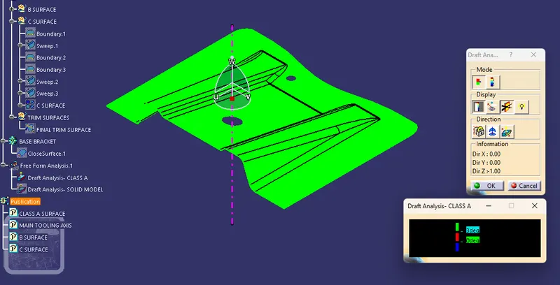
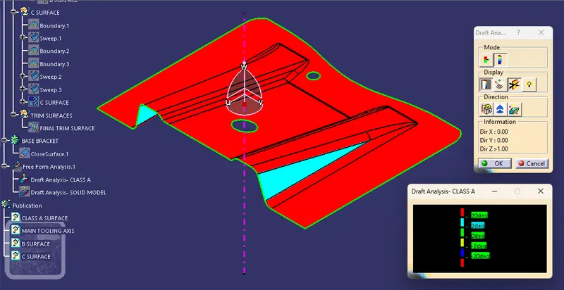
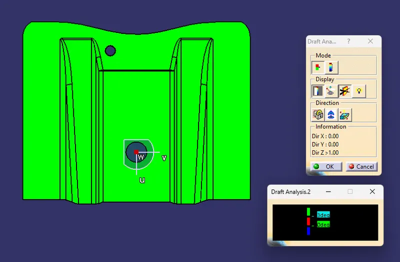
From the Draft Analysis of the Class A Surface, it is clear that a minimum draft of 3 degree is maintained for the surface as the colour code 'green' indicates that the surface passed the check which can be seen from the colour scale table. The second picture shows the detailed draft analysis for the surface ranging from -20 degree to 20 degree draft angles.
FINAL SOLID MODEL:
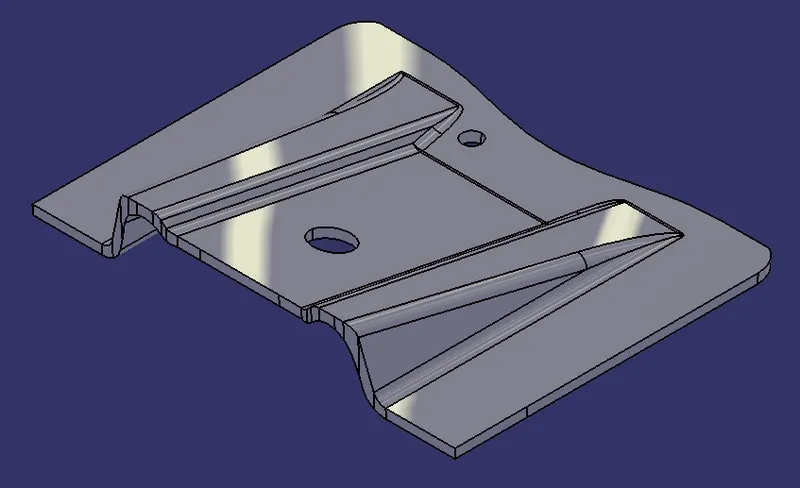
DRAFT ANALYSIS ON SOLID MODEL:
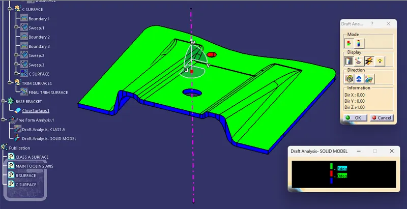
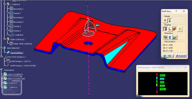
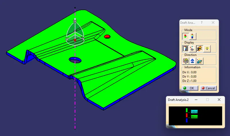
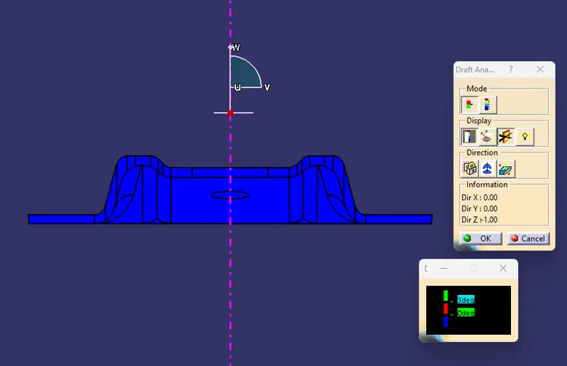
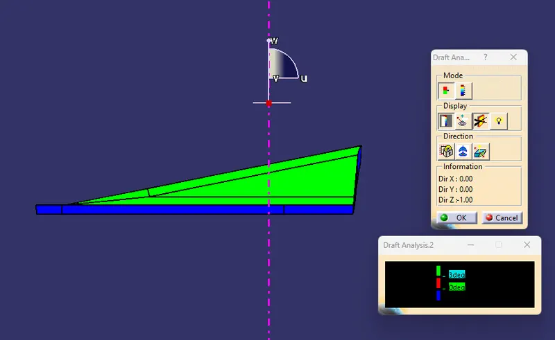
From the Draft Analysis of the Solid Part, we can conclude that the part body has a minimum of 3 degree draft for the top surface but not for the remaining surfaces as can be seen from the color scale table. A detailed draft analysis of the solid part is also provided with the color scale table.
DRAFT ANALYSIS ON SOLID MODEL IN VARIOUS ORIENTATIONS:
ISOMETRIC VIEW:
FRONT VIEW:
SIDE VIEW:
TOP VIEW: