Week 9 - Project - A pillar Design with Master Section
A pillar Design with Master Section
Aim: create a closed body component through a given class A surface and follow the master section to create attachment features.
Objective:
- Create closed body
- Create a tooling axis and follow design rules.
- Follow the Master section to create a Dog house
- Follow the master section for thickness and to create the Closed volume.
- Follow the master section to create Attachment features
- Draft analysis of the overall model of the A-pillar i.e including B side features.
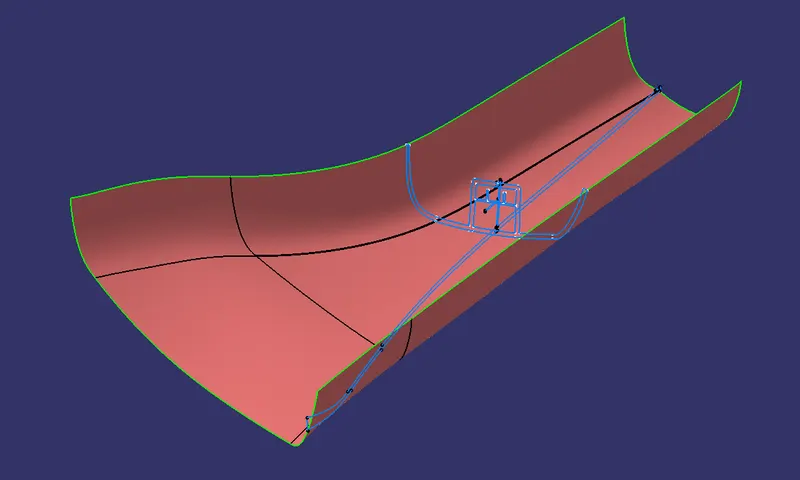
Input class A surface with master section
Introduction
MASTER SECTION:
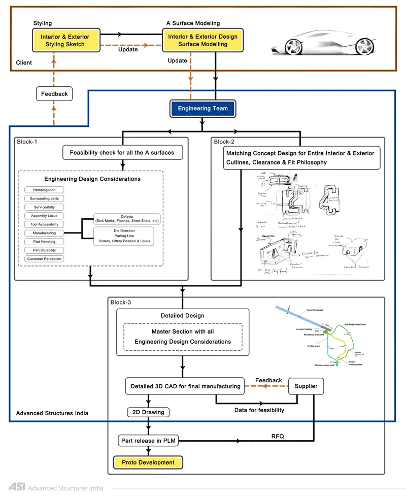
Master section development takes place during the feasibility check and concept validation stages of the product life cycle.
These are typically the guides for design requirements and which decide the component packaging after the development of the concept design, i.e class A surfaces.
The master section helps us to decide the feasibility of the concept design, the clearances, the packaging, and the fixation strategy of a component before converting the concept design into a solid 3D engineering design.
During the period of vehicle concept design, the evaluation of the master section performance depends mainly on the reference vehicle data and the experience of the structural design engineer.
DESIGNING METHODOLOGY:
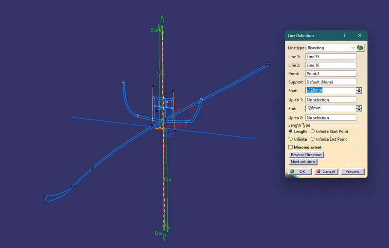
Tooling axis creation: Class-A surface is first analyzed to create the tooling axis. where the molds pull apart in injection molding. Tooling direction is essential for plastic product design as it decides the direction for mold separation.
To create the tooling axis first we have to check the best suitable direction for tooling here we have the master section of engineering features it is suitable to use that geometry to create the lines and we used the bisecting method to create the main tooling axis
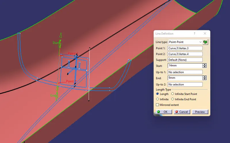
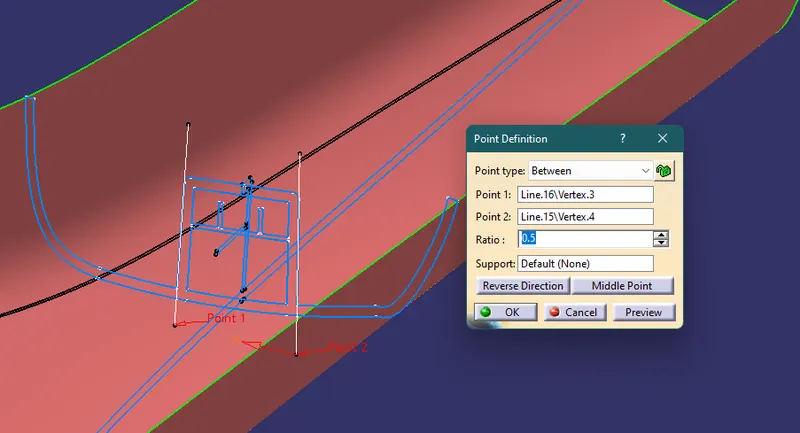
BISECTING LINES AND CREATED MAIN TOOLING AXIS
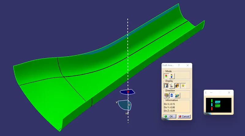
DRAFT ANALYSIS ON THE CLASS A SURFACE
After creating a tooling axis we do the draft analysis. Before drafting we have to make sure that in the view mode it is selected for the materials.
After selecting the feature draft analysis tool we drag the compass from its position to the tool axis. Then lock the compass. After that select anywhere on the component and it will give you the result.
We change the minimum draft for the component to 3°.
We can use the running point option to check the angle of the component.
As we can see in the draft analysis some surfaces are 0 to 3deg draft. as we are not class A designers we can't change the draft angle of the surfaces and this is to inform the class A designer.
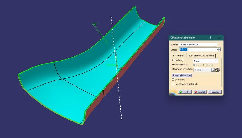
CREATION OF CLASS B SURFACE:
Creation of the class B surface first, we have to offset the entire model by 2.5mm
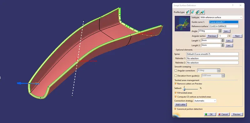
CREATION OF CLASS C SURFACE
create a boundary on the class A surface and using the sweep command with reference to the surface we created our class c surface
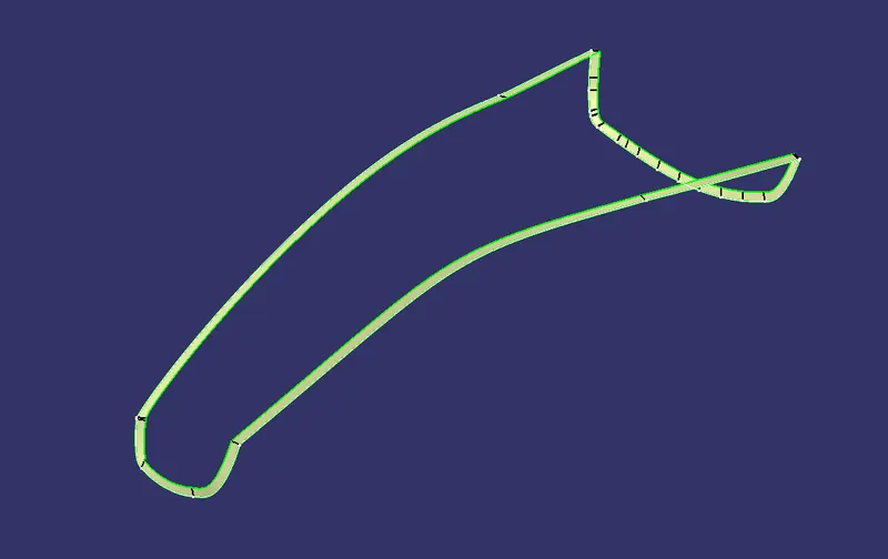
Join the class c to the class A surface
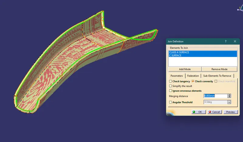
Now, the class B surface is trimmed with the join (A+C)
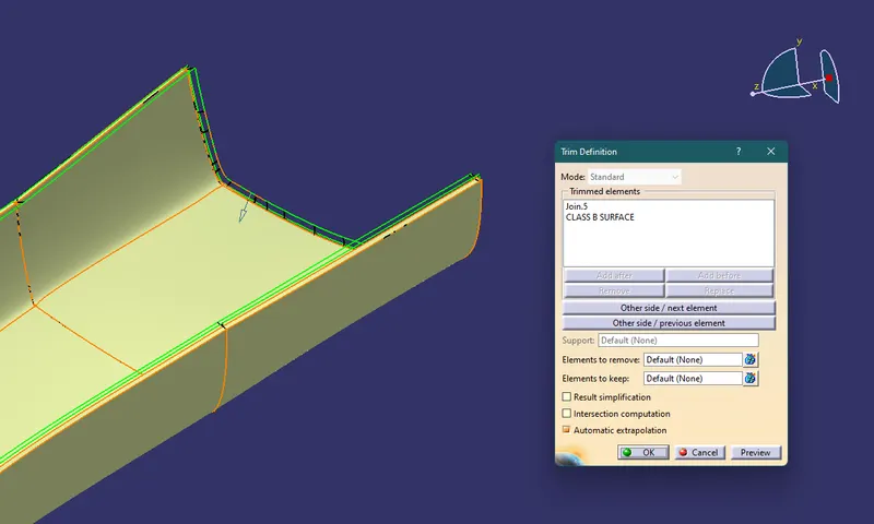
Close surface
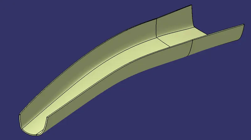
Then We go to the part design workbench and use to closed surface tool to create a solid body.
hence, we created our solid body component.
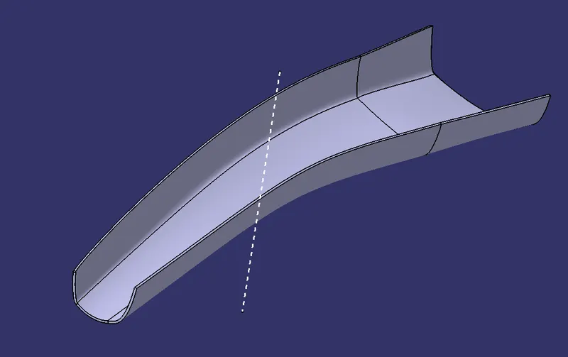
Creation of Dog house following the mastersection
Master sections are the guides for design requirements that decide the component packaging after technical (Styling, Concept, or Class-A) surfaces.
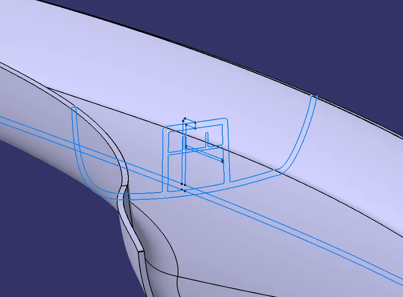
Extract the master section lines and extrude and extrapolate to the required surface length and perform the trim operation to match the master section
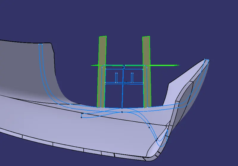
we thicken the surface by 2.5mm and split the length to the required dimension
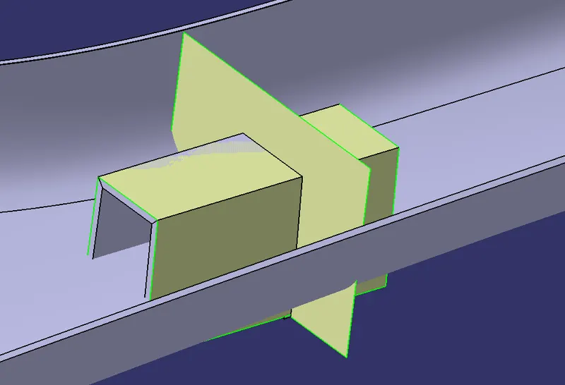
Creating a separate body. To create the inside portion we extract the lines of the master section extrude the surface and thicken the surfaces to the required dimensions.
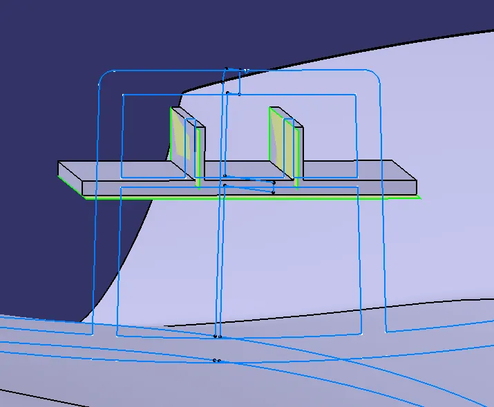
Now, the boolean operation is performed The inside portion is unitrim with the outside body
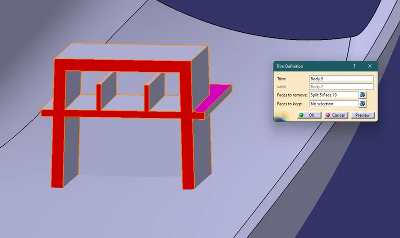
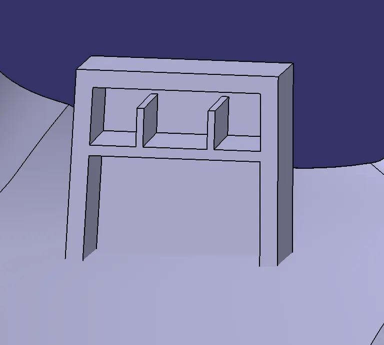
Side core axis creation
To create a side core axis we extract the surface of the dog house and to create a line we use the same point used in the creation of the main tooling axis and create a normal to the surface line and make it a side core axis.
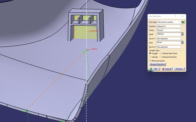
Giving 0.5deg the draft angle to the inside walls and pull direction as the side core axis
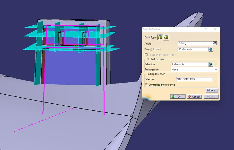
here, The Doghouse wall thickness at the intersection of the part wall should be 40% or less than the main wall
we offset the 1mm from the side wall by considering the design rule of the dog house
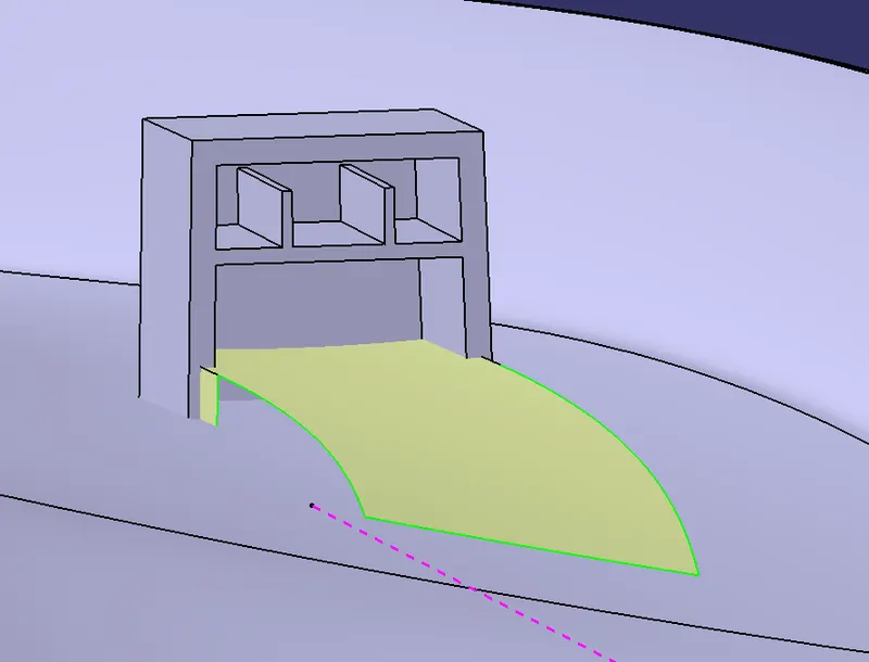
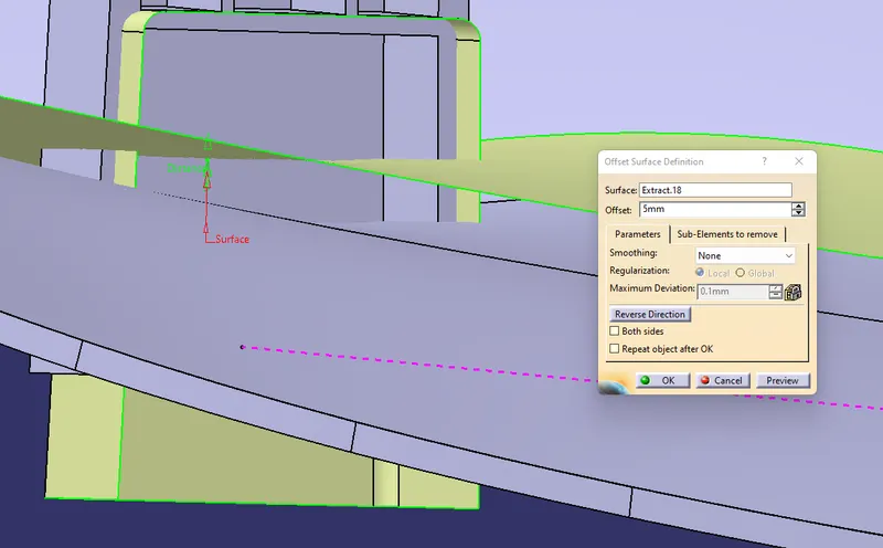
To avoid sink marks as per the design rule The height should be between 3.0 – 6.0 mm
here we offset the class b surface to 5mm
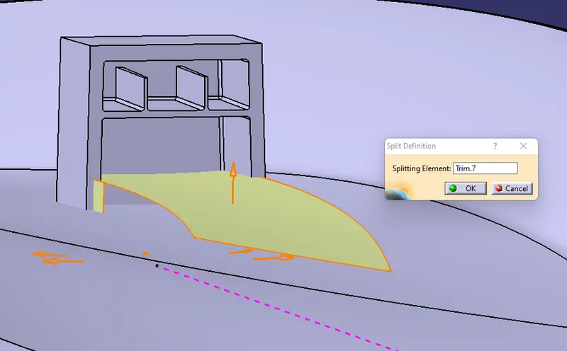
Now we trimmed the surfaces and split the surface with the part body
applying the fillets to the required edges
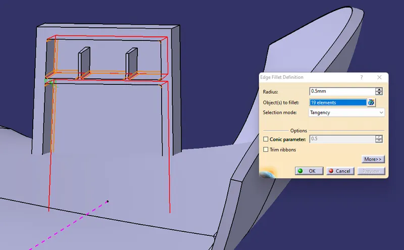
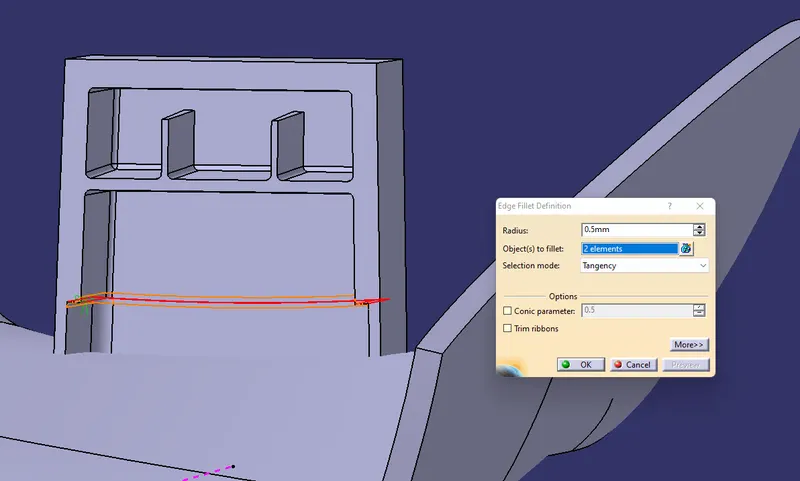
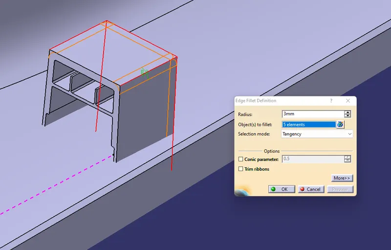
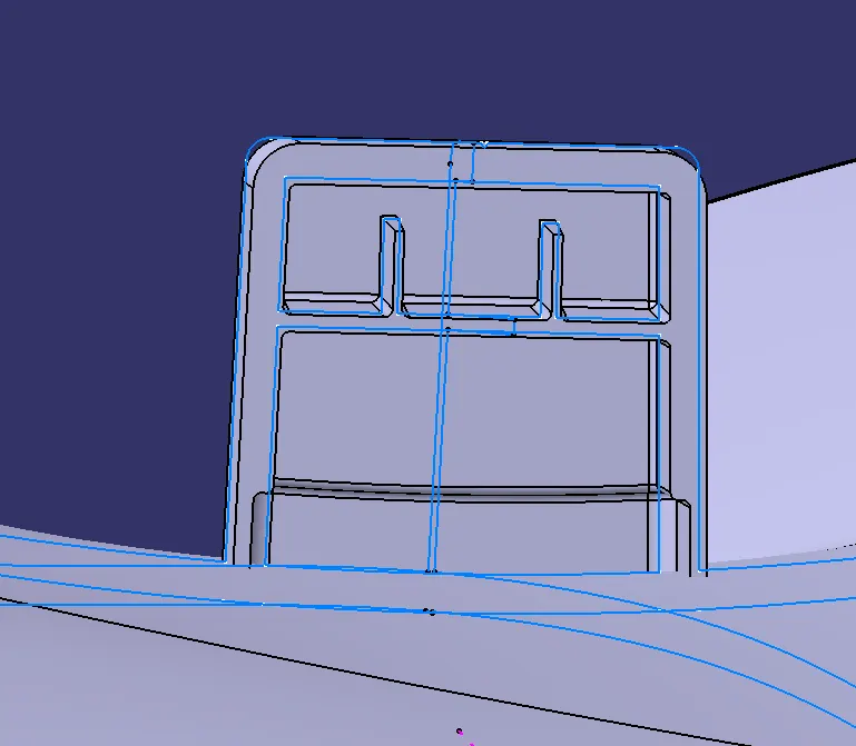
create a sketch on the top of the dog house pad it in a separate body and remove it with the main body by performing the boolean operation
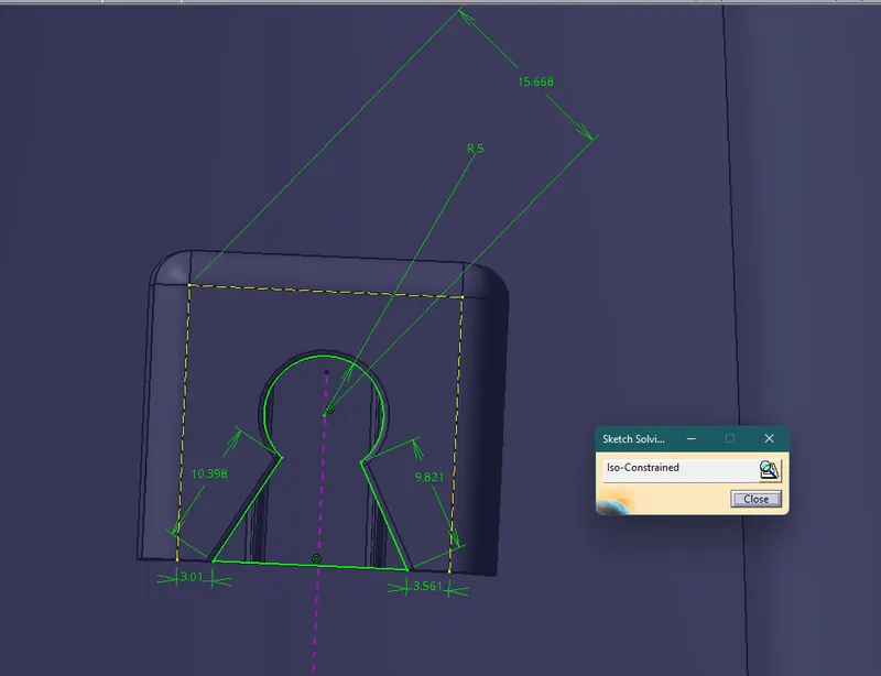
now unitrim the dog house to the main body by performing the boolean operation
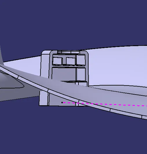
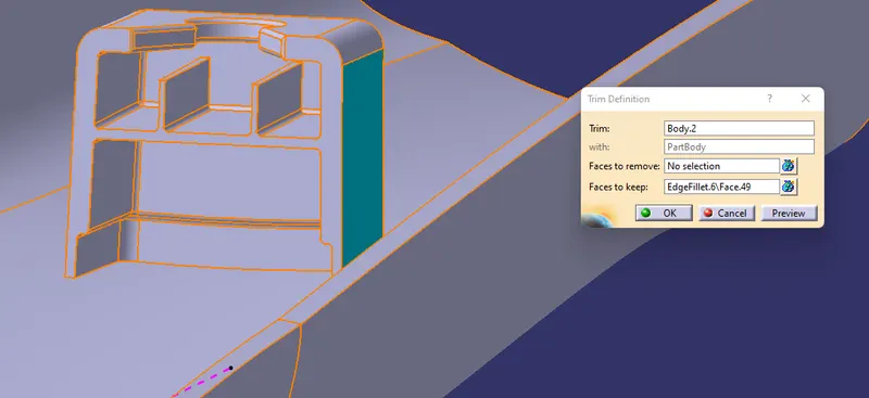
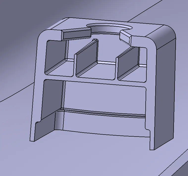
Draft analysis on the dog house with side core axis.
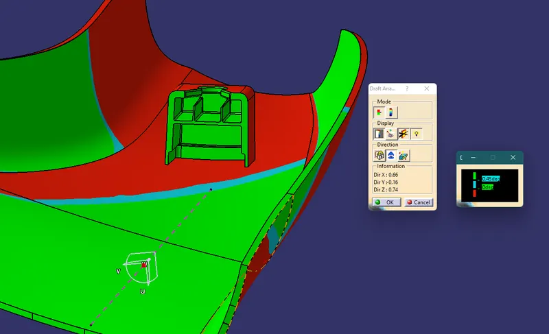
Draft analysis on dog house with Main tooling axis
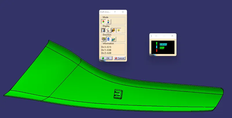
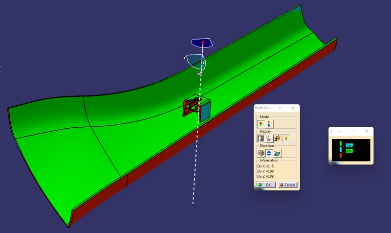
ISOMETRIC VIEW
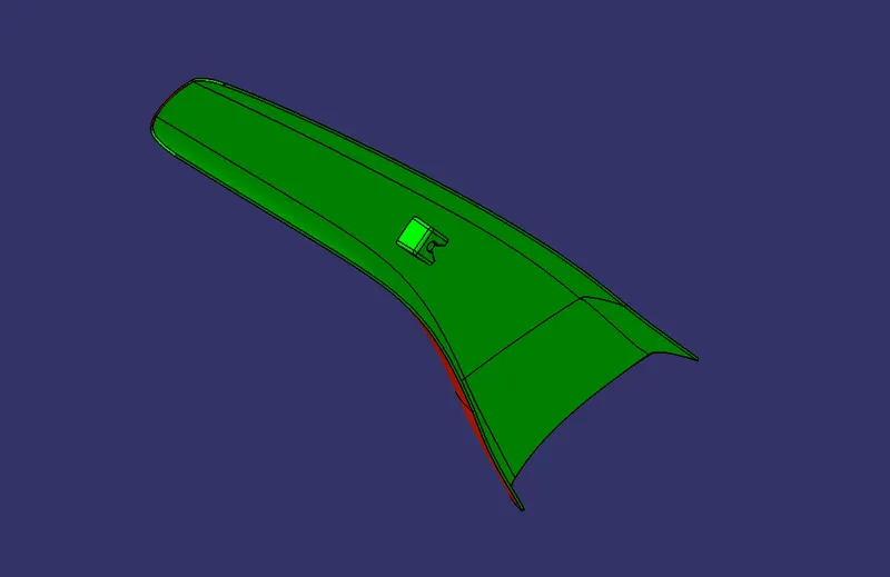
FRONT VIEW
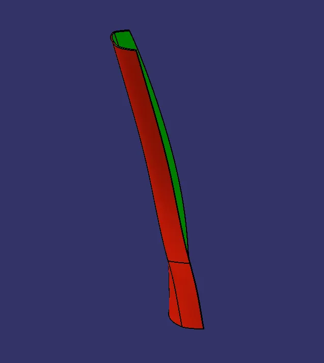
SIDE VIEW
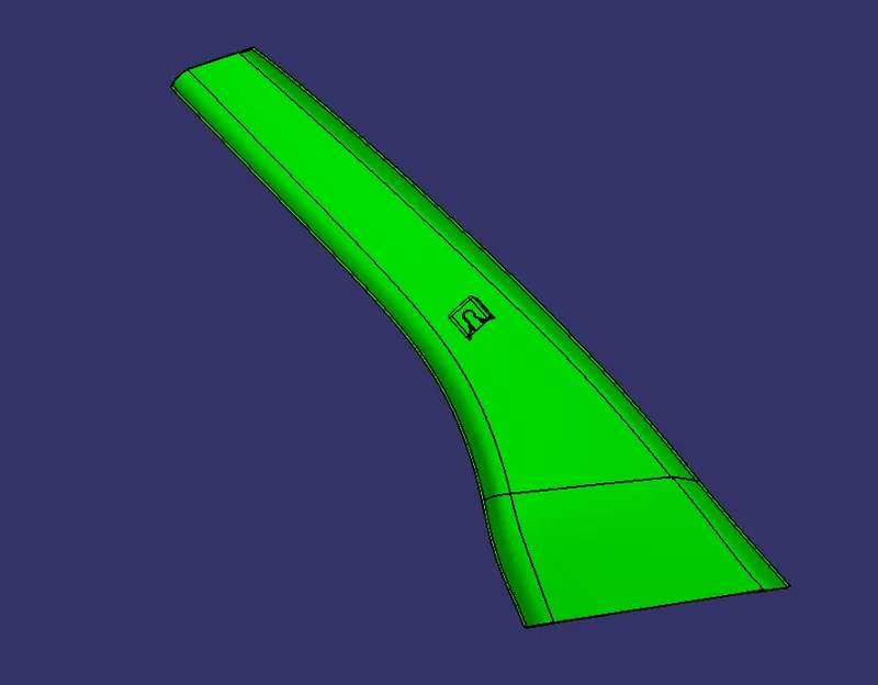
TOP VIEW
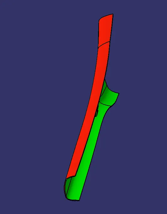 .
.
Conclusion :
Hence, The A-pillar design with master section created by considering the design rules, and the Draft analysis performed on the final component is successfully done.