Week 9 - Project - A pillar Design with Master Section
Week 9 - Project - A pillar Design with Master Section
Objective:
The main objective of this challenge is to understand the given master section to create a solid body and B-side features for a given class A surface, by considering all the design parameters.
MASTER SECTION INFO
master section is given for reference to guide the surface
Create the pillar design with master section Plastic component through the given Class-A surface. To begin with, the tooling axis for the given Class-A Surface should be created meeting the requirements of the draft angle and at the end perform the Draft analysis on the model.
Create the dog house and top cut considering the design rules mentioned in the video for the door applique.
- To Create the pillar design with the master section with Engineering Features Component from the given Class-A surface.
- To Create the tooling axis for the given Class-A Surface meeting the requirements of the draft angle.
- Creating class B surface by using offset command.
- Fixing class B offset surface making into a single part.
- to create a class C surface with a class A surface as a reference.
- To perform the Draft analysis on the model.
- creating tooling axis and checking for draft analysis if the feature is clearing or not.
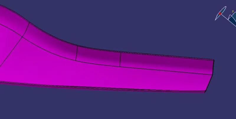
CLASS A SURFACE
Class A surface is shown below for better visual clarity.
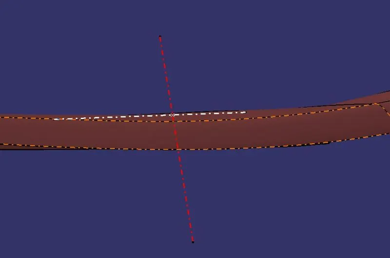
TOOLING AXIS CREATED WITH THE REFERENCE OF CLASS A SURFACE
The Tooling Direction is basically the direction that the mold pulls apart. The mold is built in two separate pieces, basically. You have a Cavity side and you have the Core side. The Core pulls apart from the Cavity, the Dye line or the Tooling Direction.
Creation of Class B:
- Now for Class B creation, we have extracted surfaces from Class A and untrimmed them to obtain the original parent surface.
- These surfaces are then offset to the required thickness.
- After offsetting, all the surfaces are trimmed into the required shape.
- Required fillets are given to the surfaces.
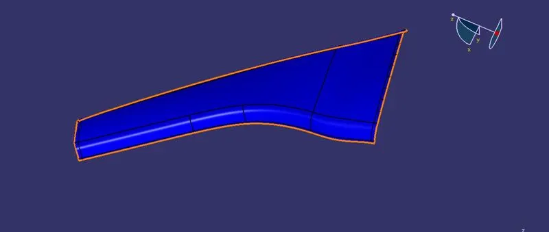
to differentate the class A and class B so we given in two different colours
C class surface :
Class C Surface has swept along the boundary CLASS A surface with respect to the tooling axis direction with a draft angle of a maximum 3 degrees minimum of 0.5 degrees.
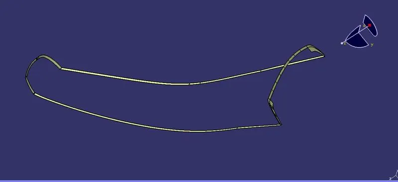
number of sweep command is used to create this class c surface
class c was created with the help of a sweep
and show bellow
also, ensure that class c should be pass 3 degrees of draft angle
complete A, B, AND C are shown in the join
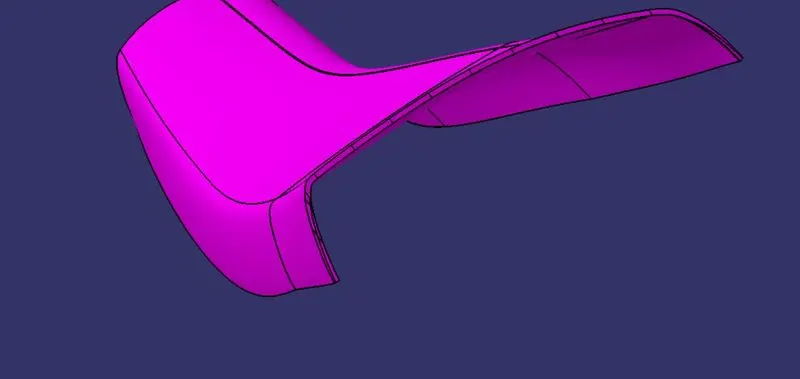
Draft analysis :
The Draft Analysis allows the user to easily analyze a part for a proper draft angle. A Draft Angle describes the amount of taper for molded or cast parts perpendicular to the parting line. Find the Draft Analysis in the Tools tab. Draft Analysis is applicable for 3D part models.
The draft analysis button within CATIA V5 will help you quickly gather the draft angle on multiple surfaces without the need for tedious manual measurements. Here is a quick rundown of how the icon works when you have a given die direction.
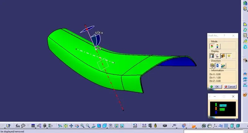
SIDE CORE TOOLING AXIS
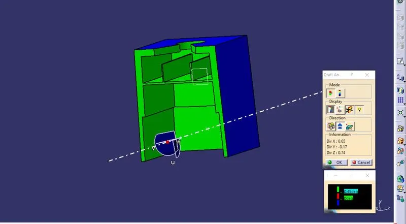
- Before going to drat analysis go to customized view parameter >under mesh >check material and then click ok.
- Now for draft analyses go to insert » analysis » feature draft analysis.
- Use the compass to define the draft direction.
- In the color, the scale changes the draft angle to 3 degrees.
- The component changes to green as an indication of the passing draft angle.
- Use a running point to check the angle on the component.
THE CLOSED BODY IS SHOWN BELLOW

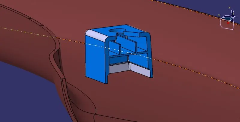
CREATING DOG HOUSE AS SHOWN IN INTERSECTION
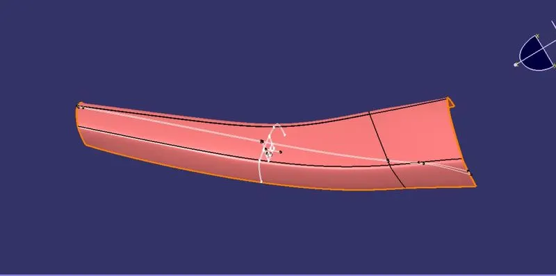
- To create the dog house on the B-side, I extracted the lines on the master section and I create a plane to extract the lines concerning the master section.
- I extracted the faces which are required to create the shell for the dog house, and I trim the surfaces with each other as per the master section dimensions.
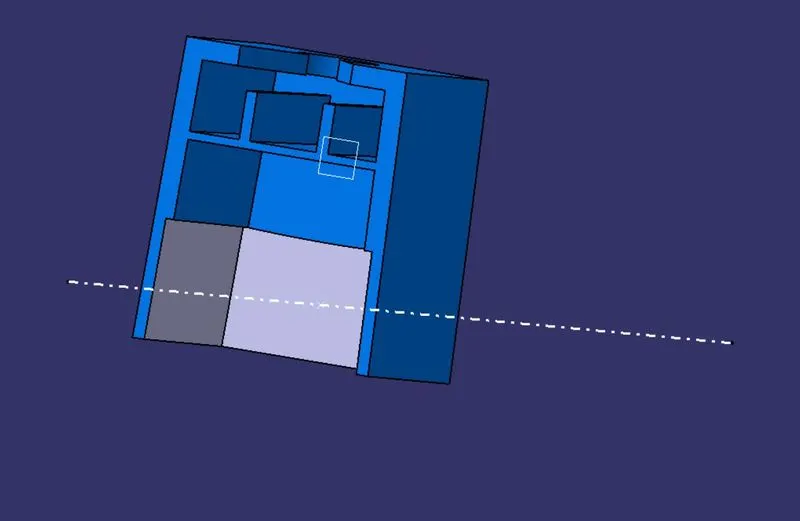
Dog house outer shell:
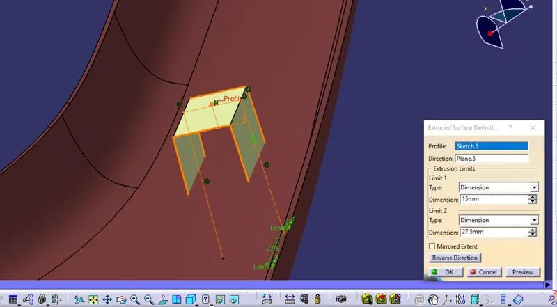
creating the plain with reference to points the sketch has been performed on the plain
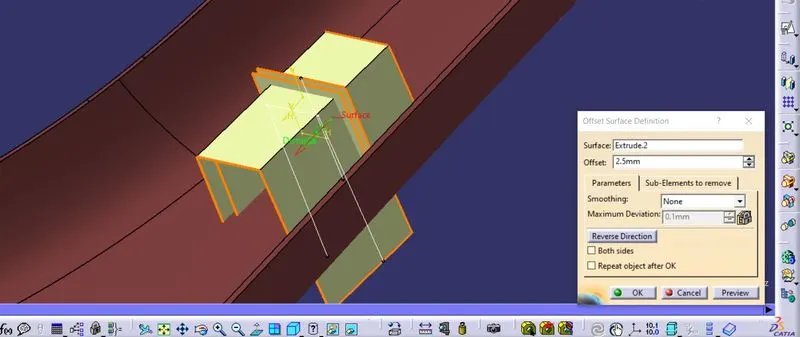
extruded the surface and offset to create an inner surface offset surface distance to 2.5 mm and spliting surface is created for both inner and outer surface
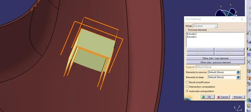
trim operation is performed to make and simple closed surface
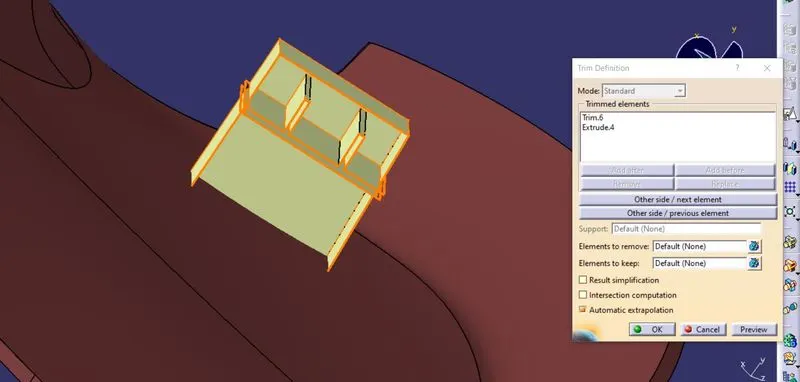
inner surface has some rids and sloted has shown in the fig abave
inner feature is created in the surface work bench
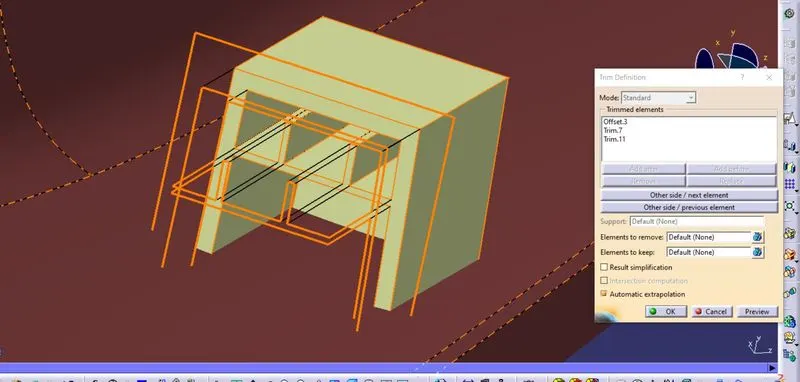
final trim is performed for this dog house inner and outer surfrace as shown in the image above
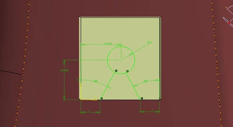
sketch is prformed at top of the dog house to make this cut out
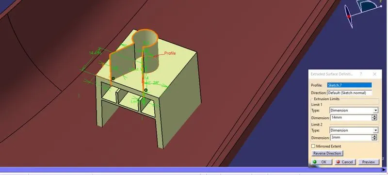
extured is performed for this sketch and extended on both side to make complete cut out
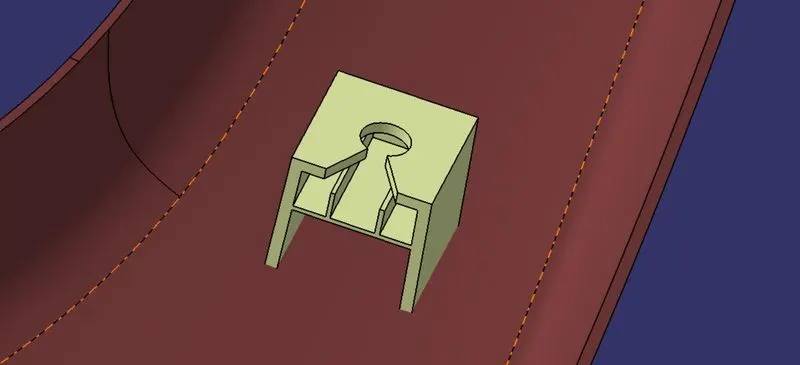
final dog house feature is shown feature is created on the top of the class B surface
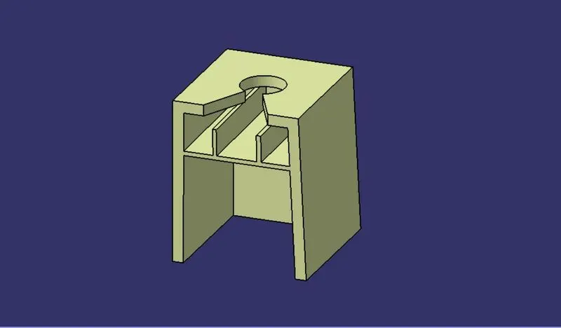
surface is supprated from the body and shown supprate surface
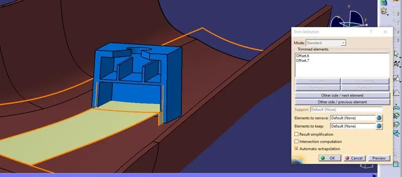
bottom cut is reated to restict the flow of the molten plastic in the dog house
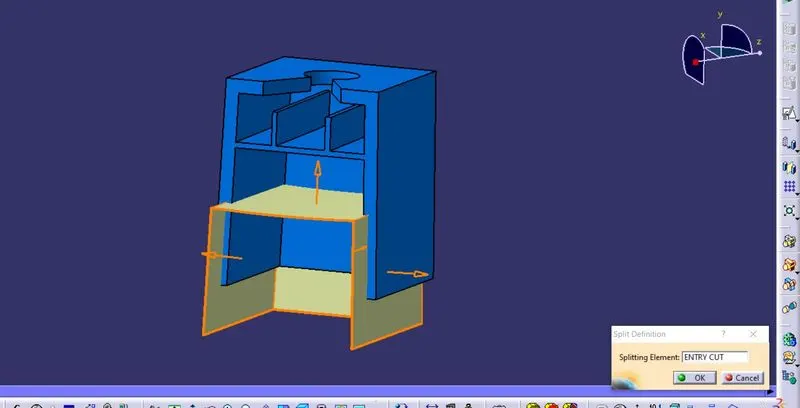
cut out is created as per the design reqirments and shown above image
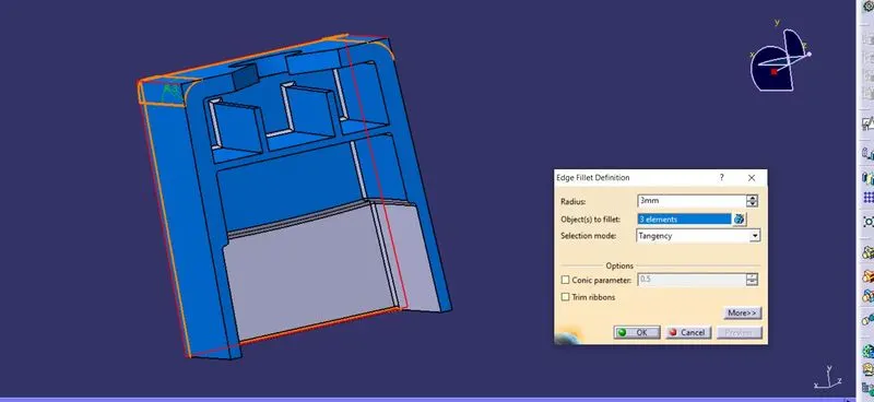
closed body is created for the dog house and edge fillet is used on each and every edge to get rid of a sharp corner
fillet value is given 3 mm on out
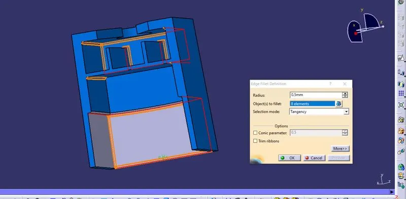
the inner surface has also given the edge fillet to avoid restriction in the flow of molten materials
the inner surface so we were given around 0.5 mm as fillet value
DRAFT FOR INNER SURFACE
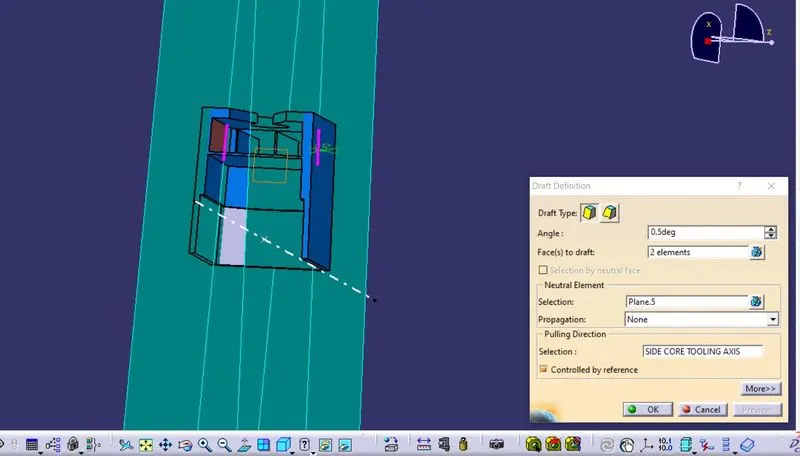
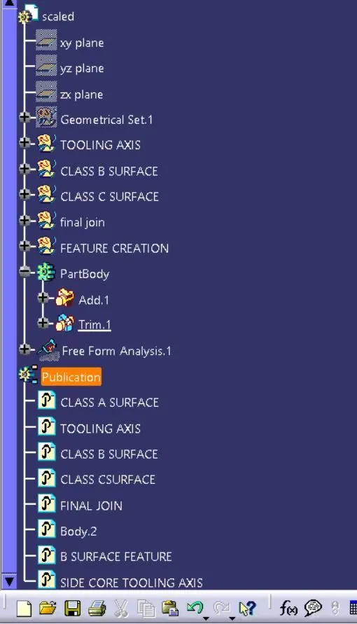
TREE
COMPLETE JOINT
the final output is shown in the image dog has and bases are attached together