Surface preparation and Boundary Flagging for NO HYDRO Simulation of Port Fuel Injection engine.
Objective
To make NO HYDRO case set up of an IC engine. Make boundary flagging and complete the setup to determine if the Geometry moves correctly during the run.
Introduction –
Surface preparation and boundary flagging are important steps before simulation setup. Surface preparation is a process to detect the error in CAD models and solve them, if neglected, it will definitely end the simulation with wrong results. Boundary flagging is a procedure in which assignment of suitable ID to the boundaries.
Port fuel injection refers to the system where the fuel is injected into the inlet manifold of the engine. The fuel mixes with the air thoroughly because there is a lot of time to mix fuel with air, during intake and compression stroke, fuel is mixed with air.
Surface preparation and boundary flagging are major steps to begin any simulation, one has to be very careful about these steps, otherwise, it will ruin the simulation. In this section, we will see the major types of error and their diagnosis, specific to converge software only. Converge automatically highlights the errors by magenta color, after the error check, but have to look at the reason behind the errors then only we can remove them.
Intersections – As the name suggests the intersection of the plane of one triangle to another plane of triangles. Areas and angles less than specified values will be also considered intersection errors. Intersection errors can be removed by translating or rotating the surfaces or increasing the angle or areas if any.
Nonmanifold Problems – Nonmanifold problems arise when an edge is shared by more than two triangles or A vertex that connects two otherwise disconnected pieces of geometry. This error will be removed automatically after assigning the boundaries or regions.
Open Edges – this problem arises when there is an open edge, since converging works on the volume so it does not allow open edges. Make patches or stitch triangles to remove this error.
Overlapping triangles -Triangles that meet other triangles at an angle less than the specified value, in degrees. Delete the overlapping triangle and make a patch if necessary.
Normal orientation – this problem arises in a triangle with a normal orientation than its adjacent one. This error can be removed easily by translating the normal.
Procedure:
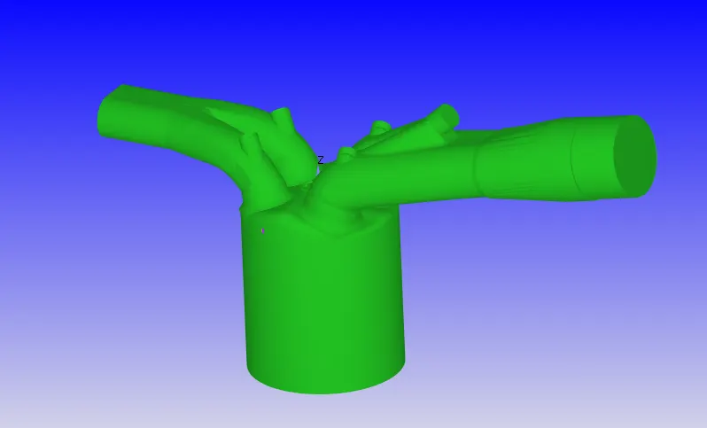
The PFI geometry .stl file is imported into the Converge Studio. The base geometry had surface errors that need to be cleared before we move up with the simulation.
Geometry
Boundary Flagging:
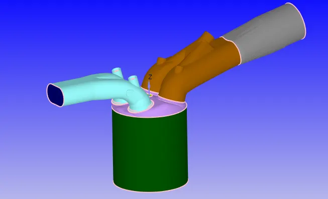
To flag the boundaries, we need to create fences across the edges of separating boundaries so it eases the selection of boundaries.
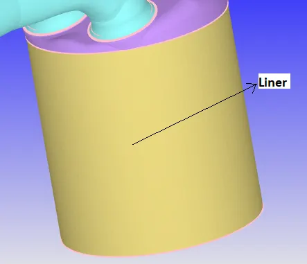
Liner:
Two edges were selected to mark the fence across the Liner edges and the boundary is flagged using the boundary fence method as shown below.
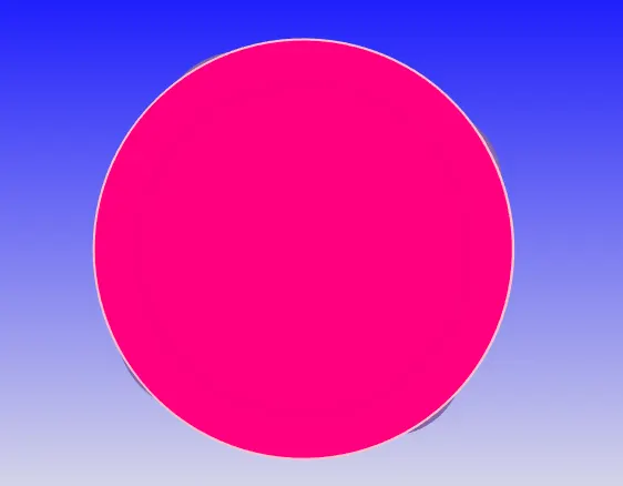
Piston:
The piston is flagged by the boundary fence method as shown below.
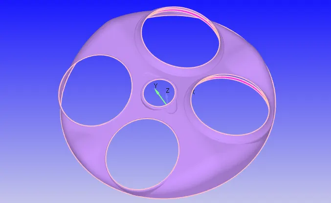
Cylinder Head:
Boundary fences are created along the 4 edges which separate the region of the ports & spark plug from the cylinder head region and the cylinder head is extracted as shown below.
Intake Port:
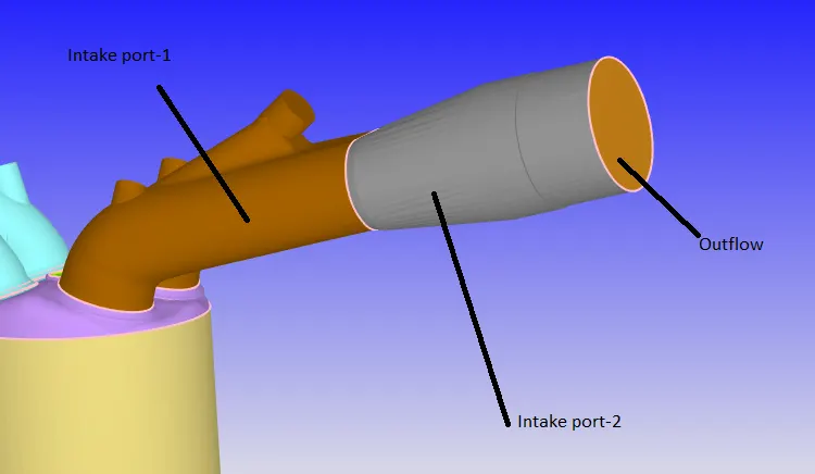
The intake port is split into two boundaries & later into two regions to separate the boundaries for different initial and boundary conditions. The intake port is where fuel spray and the air was injected. This Splitting is done to give different spray conditions at different places of the port. A fence is created using a fence between vertices and appropriate boundaries are flagged from the boundary fence method.
Exhaust Port:
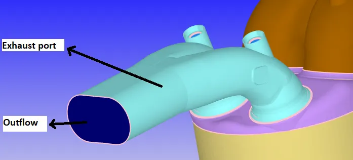
The outflow is flagged using the boundary fence method and the rest of the region as outflow as shown below.
Valves:
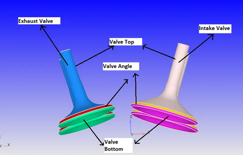
Intake & Exhaust ports, Liner, and cylinder head are hidden and then valves are visible. The valve geometry is flagged into 3 boundaries. This is done to create the events and ease the creation of disconnect triangles and assign realistic boundary conditions. Also, a translatory motion is provided to these valves by loading the motion files.
Spark Plug & Terminal:
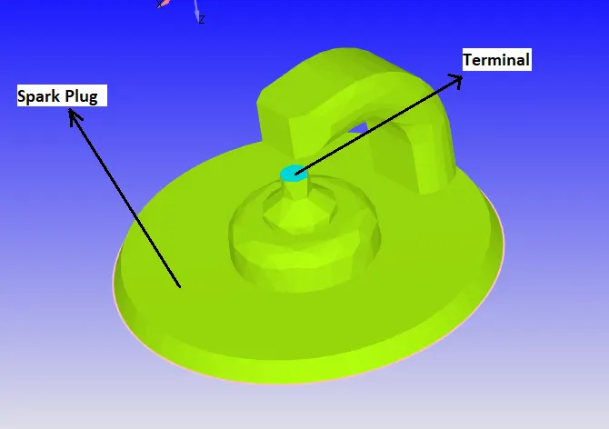
The region where the spark is generated is at a higher temperature than the rest of the spark plug. Hence, two boundaries are necessary to assign appropriate conditions.
Top of Valve top assigned to port boundaries:
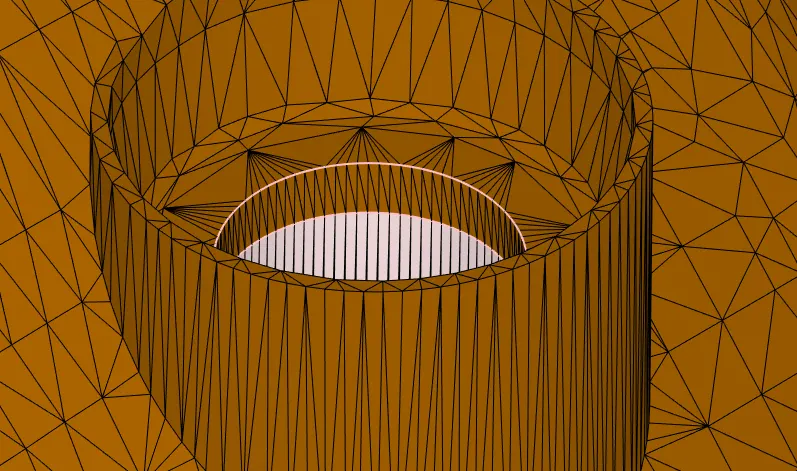
Due to the translatory motion of the valves and as it is connected to ports, during movement the surface of the ports gets distorted. To avoid this distortion, the top of the top valves is assigned to the port boundary as shown below.
Flagged boundaries:
Geometry Cleanup
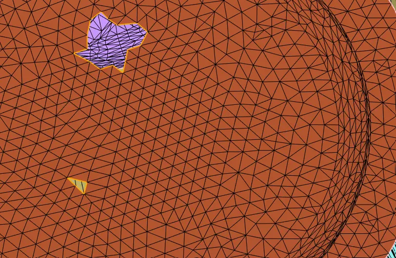
These patches in the piston were filled using a free edge loop option using the Patch tool.
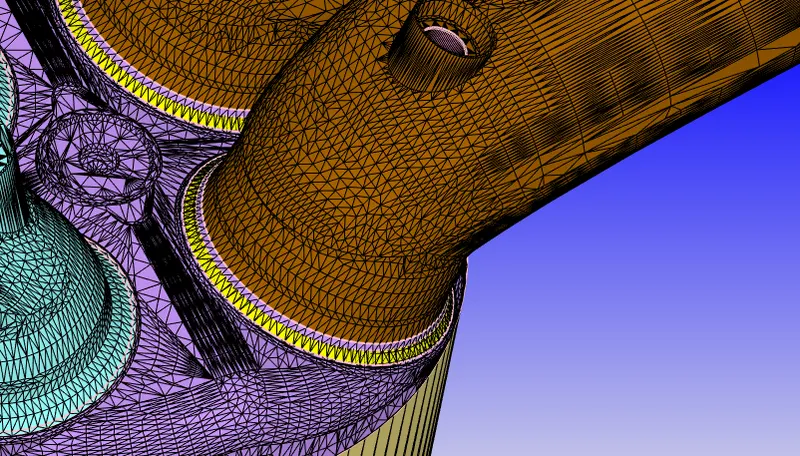
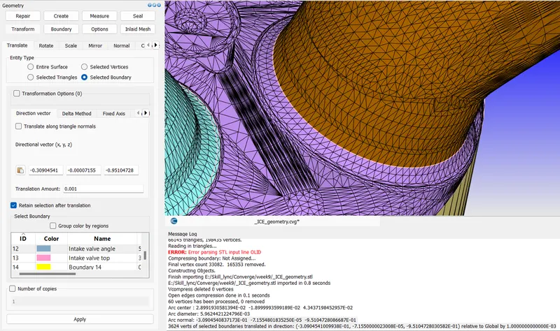
The below figure intersection of the valve and inlet port is highlighted. These intersection errors were cleared by lifting the valve by 0.1mm. As described previously the ring triangles were fenced to save the inlet port geometry from deformation. This feature retained shape at top of the inlet port.
Regions:
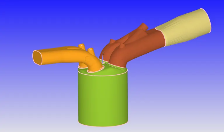
Regions were created which are used to create events between the zones and to initialize the realistic initial conditions in the flow domain. Inlet port was divided into two regions where at brown region spray forms the film. Spray should not form a film at the entry of the inlet port.
Initial and Boundary Conditions:
Engine Parameters were specified given in the below window.
Species Definition:-
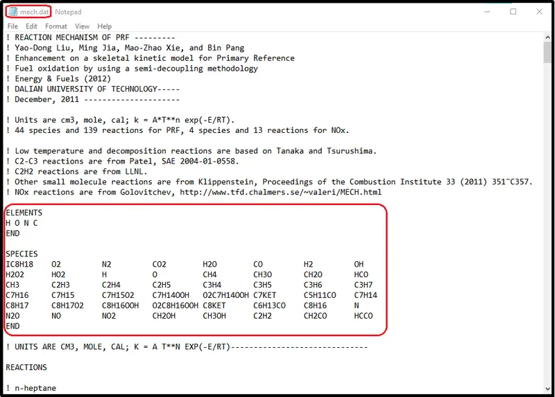
Feed the mech.dat file data in a Reaction mechanism setup
A no-hydro transient case was setup.
| Case Parameters | Setup |
| Application Type | Crank angle-based IC engine |
| Physical Parameters |
Cylinder Bore: 0.086m Stroke: 0.09m Connecting rod length: 0.18m Crank speed: 3000rpm |
| Gas Simulation | Therm.dat uploaded |
| Reaction Mechanism | Mech.dat uploaded |
| Run Parameters |
Solver - Transient Type - Crank angle-based engine simulation Simulation mode - No Hydro |
| Simulation Time Parameters |
Start time: -480 deg End time: 240 deg |
| Solver Parameters |
Solver Scheme: PISO Type: Density-based |
Boundary Conditions:
| Piston |
Boundary Type - Wall Wall motion - Translating Surface Movement - Moving Law of Wall (Piston Motion) Temperature - 450K (Law of Wall) |
| Liner |
Boundary Type - Wall Wall motion - Stationary Surface Movement - Fixed Law of Wall Temperature - 450K (Law of Wall) |
| Cylinder Head | Boundary Type - Wall
Wall motion - Stationary Surface Movement - Fixed Law of Wall Temperature - 450K (Law of Wall) |
| Exhaust Port |
Boundary Type - Wall Wall motion - Stationary Surface Movement - Fixed Law of Wall Temperature - 500K (Law of Wall) |
| Intake Port1 |
Boundary Type - Wall Wall motion - Stationary Surface Movement - Fixed Law of Wall Temperature - 425K |
| Intake Port2 |
Boundary Type - Wall Wall motion - Stationary Surface Movement - Fixed Law of Wall Temperature - 425K |
| Spark Plug |
Boundary Type - Wall Wall motion - Stationary Surface Movement - Fixed Law of Wall Temperature - 550K |
| Spark Plug Terminal |
Boundary Type - Wall Wall motion - Stationary Surface Movement - Fixed Law of Wall Temperature - 600K |
| Intake Valve |
Boundary Type - Wall Wall motion - Translating Surface Movement - Moving Law of Wall Temperature - 480K Profile - loaded Minimum Lift - 2e-4m |
| Exhaust Valve |
Boundary Type - Wall Wall motion - Translating Surface Movement - Moving Law of Wall Temperature - 525K Profile - loaded Minimum Lift - 2e-4m |
| Inflow |
Boundary Type - Inflow Temperature- 363K Pressure - 101325 Pa Species - Air |
| Outflow |
Boundary Type - Outflow Temperature- 800K Pressure - 101325 Pa Species - CO2 - 0.192304 H20 - 0.088559 N2 - 0.719137 |
Regions:
| Cylinder Region |
Temperature - 1360K Pressure - 185731 Pa Species - CO2 - 0.192304 H20 - 0.088559 N2 - 0.719137 |
| Intake Port 1 |
Temperature - 390K Pressure - 101325Pa Species IC8H18 - 0.025508 O2 - 0.20157 N2 - 0.77292 |
| Intake Port 2 |
Temperature - 370K Pressure - 101325Pa Species - Air |
| Exhaust Region |
Temperature - 1360K Pressure - 185731 Pa Species - CO2 - 0.192304 H20 - 0.088559 N2 - 0.719137 |
Events:
| Cyclic |
Between Cylinder region & Intake Port 1, Period -720 deg, Event - Valve Between Cylinder region & Exhaust Region, Period -720 deg, Event - Valve |
| Permanent | Between Intake Port 1 & Intake Port 2, Event -Open |
Mesh Size:
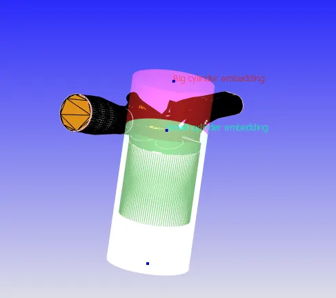
A base grid of 0.004m is used along with the fixed embedding. For the Intake and Exhaust valve angle scales of 3 and 1 embedding layer were used with Permanent Mode. Whereas, for the Cylinder region and zones next to the valves in the ports a cylinder entity is used with a scale of 2 & 1, respectively.
Animation
Conclusion:-
- The simulation was set up to check the valve movement and mesh generation in IC Engine Geometry.
- No hydrodynamic simulation setup is always vital to verify the simulation setup.
- Simulation setup is refined more at valves which could be easily identified in animation video.