Simulation of a backward facing step in OpenFOAM
Aim: To simulate an incompressible-laminar-viscous flow through the backward-facing step geometry. The simulation must be Transient.
- Analyze and simulate flow through the backward-facing steps.
- Creating meshes - mesh grading factors: 0.2, and without mesh grading factors.
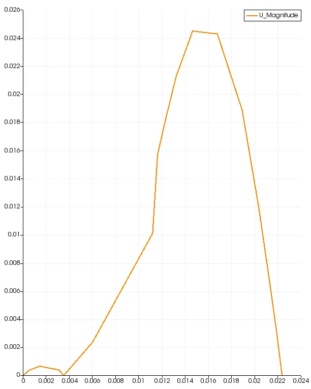
- Measuring the velocity profile at 8.5 m from the inlet of geometry.
- Compare velocity magnitude contours near the step region for the above-mentioned grading factors.
- To understand how different quantities like velocity, pressure behaves due to sudden step.
Incompressible flow: The flow in which there is no change in the density is called the incompressible flow. Mathematically, an incompressible flow can be expressed as `∇⋅u=0` `Re=ρ⋅v⋅L/μ`.
Laminar Flow: In fluid dynamics, laminar flow is characterized by fluid particles following smooth paths, in layers with little or no mixing. Laminar flow generally occurs when the fluid is moving slowly or the fluid is very viscous. f the Reynolds number is very small, much less than 1, then the fluid will exhibit Stokes, or creeping, flow, where the viscous forces of the fluid dominate the inertial forces.
At low velocities, the fluid tends to flow without lateral mixing, and adjacent layers slide past one another like playing cards. There are no cross-currents perpendicular to the direction of flow, nor eddies or swirls of fluids. In laminar flow, the motion of the particles of the fluid is very orderly with particles close to a solid surface moving in straight lines parallel to that surface. Laminar flow is a flow regime characterized by high momentum diffusion and low momentum convection.
Reynolds number is the parameter to differentiate that a flow is turbulent or laminar.
Whenever the Reynolds number is less than 2000, flow in a pipe is laminar, whereas values greater than 2000, flow is usually turbulent
Mathematically Reynolds number is the ratio of inertial forces to viscous forces.
`Re=(rhoVl)/mu`
`rho` is the density of the liquid `((kg)/m^3)`.
`V` is the velocity of the fluid (m/s).
`l` is the characteristic linear dimension. (m)
`mu` is the dynamic viscosity of the fluid. (Pa.s or `(N.s)/m^2` or `(kg)/(m.s)`)
Viscous Flow:
A type of fluid flow in which there is a continuously steady motion of particles; the motion of the fixed point always remains constant.
The fluid flows in form of a layer. The layer which sticks with the wall has zero velocity which is called the no-slip condition. and it develops frictional effect at the walls. Viscous flows occur when the effects of fluid viscosity are balanced by those arising from fluid inertia, body forces, and/or pressure gradient. In such flows, scaling analyses do not allow a priori neglect of any terms in the equations of fluid motion.
The slower layer tries to reduce the speed of the lower layer.
Mesh grading:
Mesh grading is used to save computational memory and time required to obtain the solution. With the required amount of cells, we can obtain the required results by concentrating on the required region where we need accurate results for eg. (near-wall region).
grading factor= `"size of the last cell"/"size of the first cell"`
Procedure
1) We need to know which solver we will use to solve the problem. OpenFOAM has tutorial folders that we can access and take insights into what the solver will do.
2) For our case of incompressible laminar viscous flow solution we need to use an icoFoam solver. It solves the incompressible laminar Navier-Stokes equation (continuity and momentum) using PISO Algorithm.
3)The solver tutorial from the incompressible icoFoam called cavity is chosen for the task and its geometry and initial condition are modified as per objective.
4) Solver file called BlockMeshDict in the tutorials system folder creates the geometry and mesh, hence this is modified to create the backward-facing step. The geometry is divided into 5 blocks and each block is assigned with indexing the vertices.
5) The block is started with the 0th block and the block is formed starting with 0.
- OpenFOAM Geometry

6) We now set up the case with blocmeshDict file by assigning Boundary and wall mesh conditions, time step and end time in the controldict file and initial conditions in the velocity and pressure file.The end time must be judiciously chosen to as per the requirement of the flow to be fully developed.
7)Once the geometry is created we assign the boundary conditions for the flow to take place within the geometry.
8) `Delta T` is specified as `0.01` and `end time=20s`.
Mesh Specification
no of cells along x(longer direction)=200
no of cells along y direction=10
grading factor=0.2
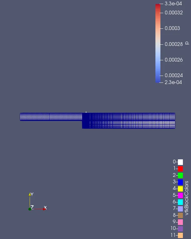
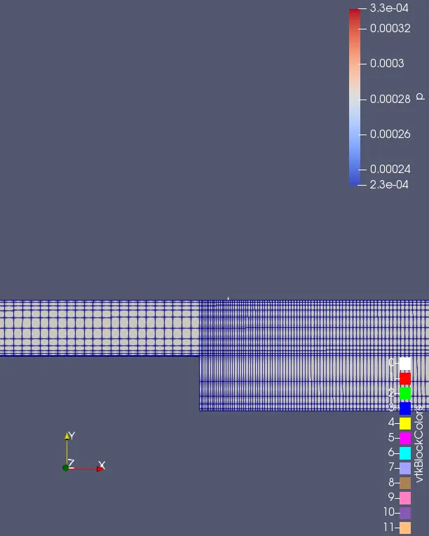
Blockmeshdict file for frading factor 0.2 along with specified boundary conditions
*--------------------------------*- C++ -*----------------------------------*
  =========                 |
  \      /  F ield         | OpenFOAM: The Open Source CFD Toolbox
   \    /   O peration     | Website:  https://openfoam.org
    \  /    A nd           | Version:  9
     \/     M anipulation  |
*---------------------------------------------------------------------------*/
FoamFile
{
    format      ascii;
    class       dictionary;
    object      blockMeshDict;
}
// * * * * * * * * * * * * * * * * * * * * * * * * * * * * * * * * * * * * * //

convertToMeters 0.01;

vertices
(
    (0 0 0) //0
    (8 0 0) //1
    (8 0.5 0) //2
    (0 0.5 0) //3
    (8 1 0)//4
    (0 1 0)//5
    (20 1 0)//6
    (20 0.5 0)//7
    (20 0 0)//8
    (20 -1 0)//9
    (8 -1 0)//10
    (0 0 1)//11
    (8 0 1)//12
    (8 0.5 1)//13
    (0 0.5 1)//14
    (8 1 1)//15
    (0 1 1)//16
    (20 1 1)//17
    (20 0.5 1)//18
    (20 0 1)//19
    (20 -1 1)//20
    (8 -1 1)//21
);

blocks
(
    hex (0 1 2 3 11 12 13 14) (50 5 1)   simpleGrading (1 5 1)
    hex (3 2 4 5 14 13 15 16) (50 5 1)   simpleGrading (1 0.2 1)
    hex (2 7 6 4 13 18 17 15) (150 5 1)  simpleGrading (5 0.2 1)
    hex (1 8 7 2 12 19 18 13) (150 5 1)  simpleGrading (5 5 1)
    hex (10 9 8 1 21 20 19 12) (150 5 1) simpleGrading (5 10 1)
);

edges
(
);

boundary
(
    inlet
    {
        type patch;
        faces
        (
            (0 11 14 3)
            (3 14 16 5)
        );
    }
    outlet
    {
        type patch;
        faces
        (
            (9 8 19 20)
            (8 7 18 19)
            (7 6 17 18)
        );
    }
    walls
    {
        type wall;
        faces
        (
            (4 5 16 15)
            (6 4 15 17)
            (0 1 12 11)
            (10 9 20 21)
            (10 21 12 1)
        );
    }
);

mergePatchPairs
(
);
Initial Conditions
For velocity
/*--------------------------------*- C++ -*----------------------------------*
  =========                 |
  \      /  F ield         | OpenFOAM: The Open Source CFD Toolbox
   \    /   O peration     | Website:  https://openfoam.org
    \  /    A nd           | Version:  9
     \/     M anipulation  |
*---------------------------------------------------------------------------*/
FoamFile
{
    format      ascii;
    class       volVectorField;
    object      U;
}
// * * * * * * * * * * * * * * * * * * * * * * * * * * * * * * * * * * * * * //

dimensions      [0 1 -1 0 0 0 0];

internalField   uniform (0 0 0);

boundaryField
{
    inlet
    {
        type            fixedValue;
        value           uniform (0.02 0 0);
    }

    outlet
    {
        type            zeroGradient;
    }

    walls
    {
        type            noSlip;
    }
}

// ************************************************************************* //
Pressure
/*--------------------------------*- C++ -*----------------------------------*
  =========                 |
  \      /  F ield         | OpenFOAM: The Open Source CFD Toolbox
   \    /   O peration     | Website:  https://openfoam.org
    \  /    A nd           | Version:  9
     \/     M anipulation  |
*---------------------------------------------------------------------------*/
FoamFile
{
    format      ascii;
    class       volScalarField;
    object      p;
}
// * * * * * * * * * * * * * * * * * * * * * * * * * * * * * * * * * * * * * //

dimensions      [0 2 -2 0 0 0 0];

internalField   uniform 0;

boundaryField
{
    inlet
    {
        type            zeroGradient;
    }

    outlet
    {
        type            fixedValue;
        value           uniform 0;
    }

    walls
    {
        type            zeroGradient;
    }
}

// ************************************************************************* //
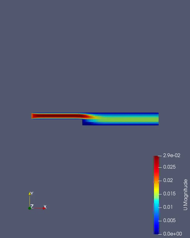
After running the simulations with grading factor 0.2. we post process the results in Paraview Software.
velocity contour
The mesh with non-refined regions has the same boundary and initial conditions.
But mesh ratio is not assigned.
/*--------------------------------*- C++ -*----------------------------------*
  =========                 |
  \      /  F ield         | OpenFOAM: The Open Source CFD Toolbox
   \    /   O peration     | Website:  https://openfoam.org
    \  /    A nd           | Version:  9
     \/     M anipulation  |
*---------------------------------------------------------------------------*/
FoamFile
{
    format      ascii;
    class       dictionary;
    object      blockMeshDict;
}
// * * * * * * * * * * * * * * * * * * * * * * * * * * * * * * * * * * * * * //

convertToMeters 0.01;

vertices
(
    (0 0 0) //0
    (8 0 0) //1
    (8 0.5 0) //2
    (0 0.5 0) //3
    (8 1 0)//4
    (0 1 0)//5
    (20 1 0)//6
    (20 0.5 0)//7
    (20 0 0)//8
    (20 -1 0)//9
    (8 -1 0)//10
    (0 0 1)//11
    (8 0 1)//12
    (8 0.5 1)//13
    (0 0.5 1)//14
    (8 1 1)//15
    (0 1 1)//16
    (20 1 1)//17
    (20 0.5 1)//18
    (20 0 1)//19
    (20 -1 1)//20
    (8 -1 1)//21
);

blocks
(
    hex (0 1 2 3 11 12 13 14) (50 5 1)   simpleGrading (1 1 1)
    hex (3 2 4 5 14 13 15 16) (50 5 1)   simpleGrading (1 1 1)
    hex (2 7 6 4 13 18 17 15) (150 5 1)  simpleGrading (1 1 1)
    hex (1 8 7 2 12 19 18 13) (150 5 1)  simpleGrading (1 1 1)
    hex (10 9 8 1 21 20 19 12) (150 5 1) simpleGrading (1 1 1)
);

edges
(
);

boundary
(
    inlet
    {
        type patch;
        faces
        (
            (0 11 14 3)
            (3 14 16 5)
        );
    }
    outlet
    {
        type patch;
        faces
        (
            (9 8 19 20)
            (8 7 18 19)
            (7 6 17 18)
        );
    }
    walls
    {
        type wall;
        faces
        (
            (4 5 16 15)
            (6 4 15 17)
            (0 1 12 11)
            (10 9 20 21)
            (10 21 12 1)
        );
    }
);

mergePatchPairs
(
);

// ************************************************************************* //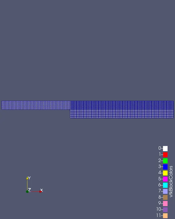
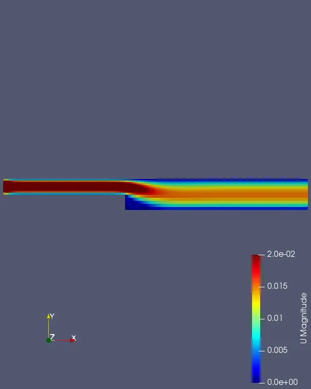
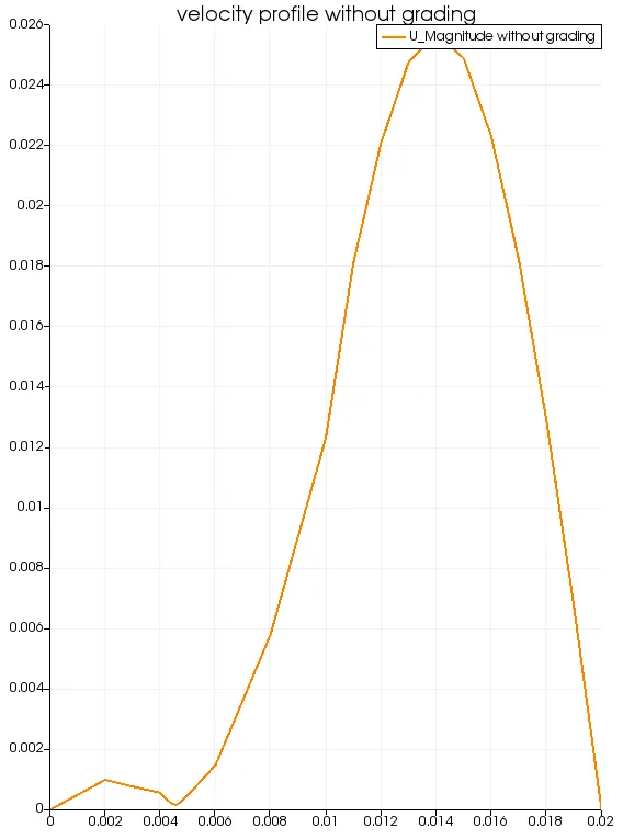
From the simulations, we can see that at the step, the flow gets detached from the wall and is separated. At the separation point which we can observe through the different mesh grading factors results, there is slight variation in flow. Now at this separation point, there is a low-pressure region created which causes the flow to recirculate. This gives rise to something called a recirculation zone or wake region.
As the fluid crosses the step region, the area increases. Now looking at the region in the graph from 0 to 1, the top part of the geometry after step, compared to the upstream region at x = 4 m, The velocity decreases at x= 8.5 m due to increased area. The fluid expands its area of flow and it also mixes with the flow from the recirculation zone. For different grading factors, as the mesh becomes finer at 0.2 we can see the velocity drop curve, it can be noticed that wider and clearer indication of the result we're anticipating. The ungraded mesh gets coarser yet it's still observable what we concluded from the above graph. But as the mesh gets coarser at the regions the results are slightly different from finer mesh. For the region before the step, from -1 to 0, this is the recirculation zone, Overall the velocity magnitude profile gives similar results in general but with a mesh grading factor, it is observed that finer results can be obtained with finer mesh and more accuracy can be aimed in solution.