Week 9: Project 1 - Surface preparation and Boundary Flagging (PFI)
AIM:
The Tasks that need to be performed on the given geomtery model are
1, Boundary Flagging.
2, Surface preparartion.
DESCRIPTION:
For the model to check the geometry diagnosis and look for the errors in surface and fix them accordingly and then to do the boundary flagging for the same.
Opening the model in Converge studio
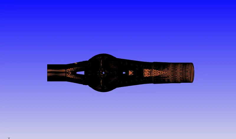
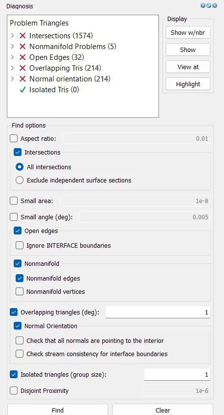
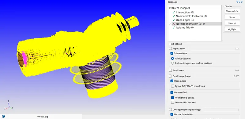
Checking for model errors for geometry diagnosis we see so many errors
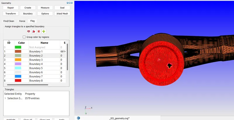
Now doing the boundary flagging and assigning as follows
For piston
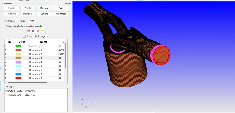
For inlet port
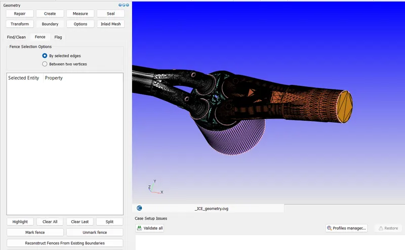
By using boundary fence we create the fence to assign the boundary
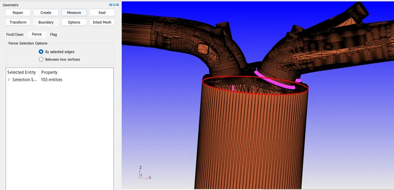
Fence as follows
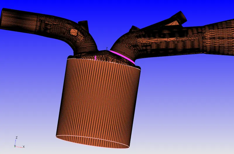
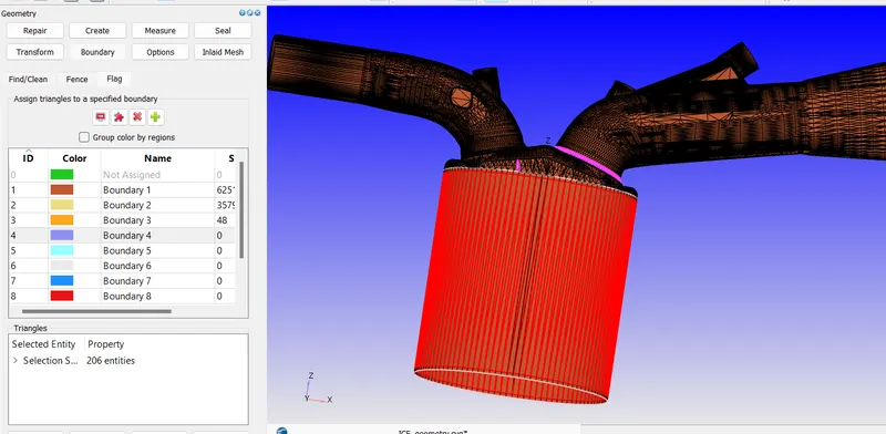
Now adding to the boundary using Boundary fence selection and naming as 'liner'
Creating boundary fence
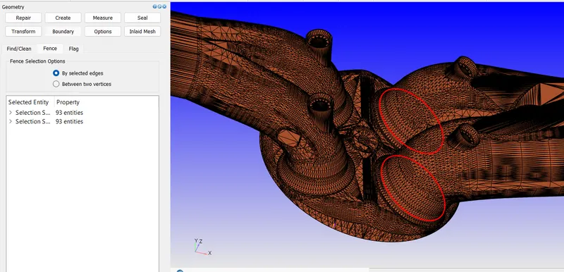
Fence as follows
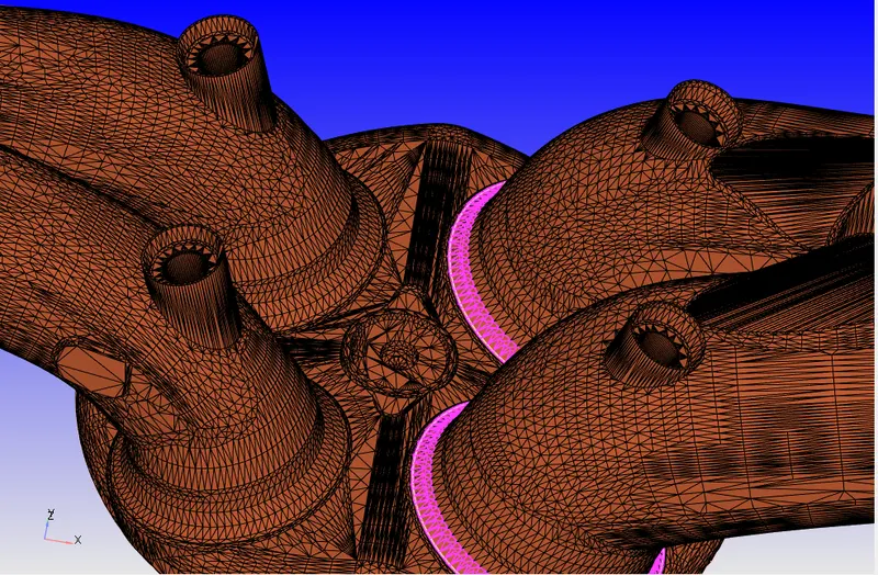
Similarly creating fences around other ports
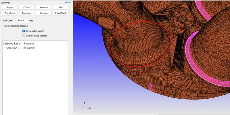
Assigning the boundary to cylinder head
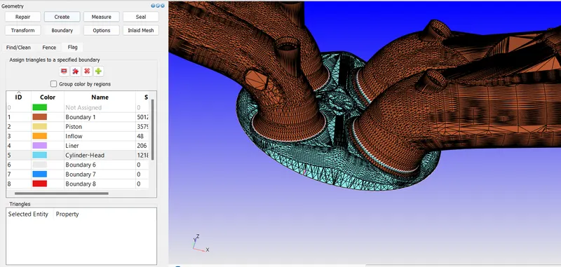
For exhaust port
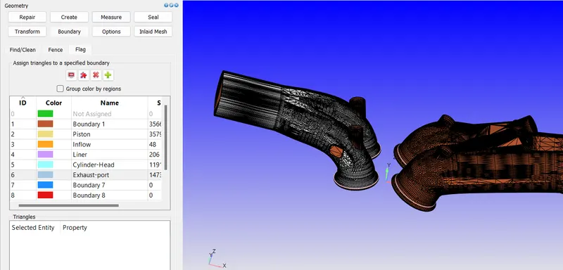
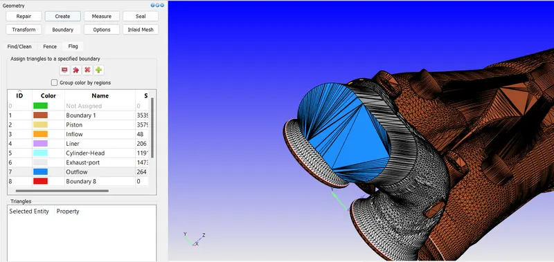
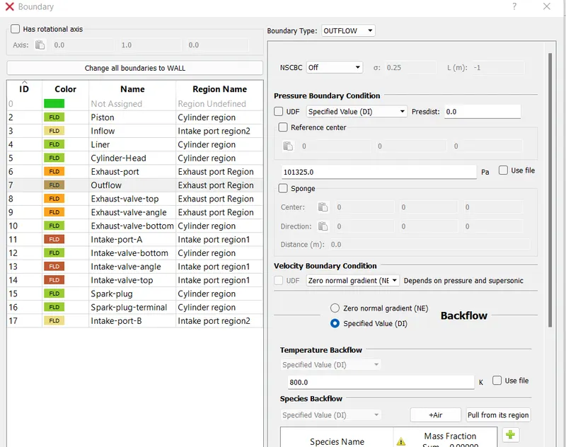
For outflow
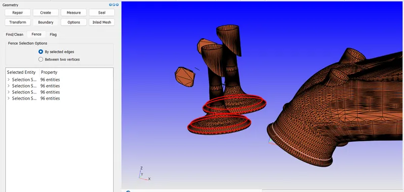
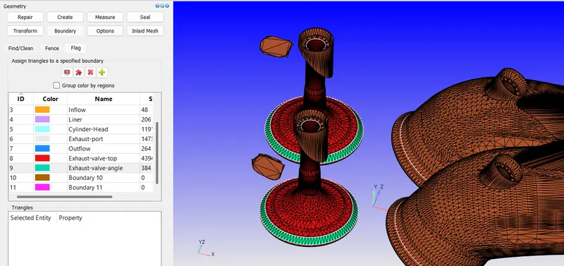
Creating fences for valves as follows
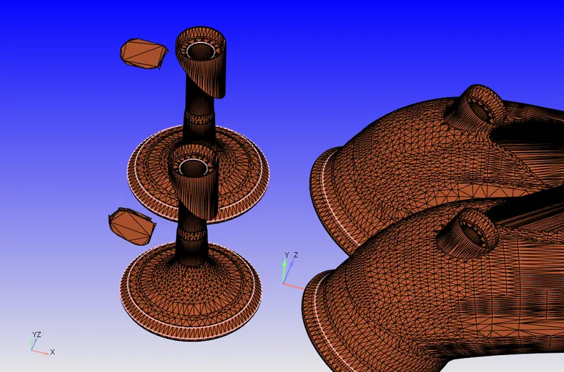
Assigning boundary to exhaust valve
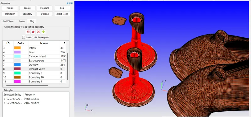

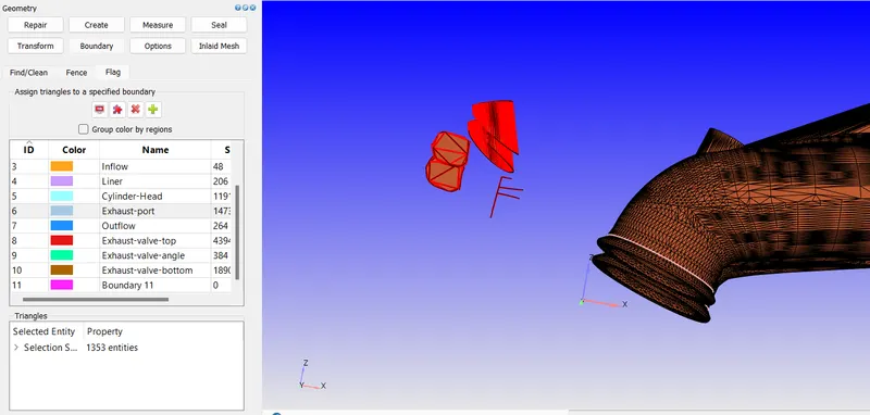
Group selecting and applying remaining components to exhaust port
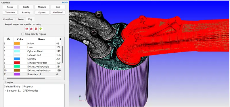
Using reconstruct fences from existing boundaries creating the fences and assigning boundaries to other components
For intake port
For intake valve bottom
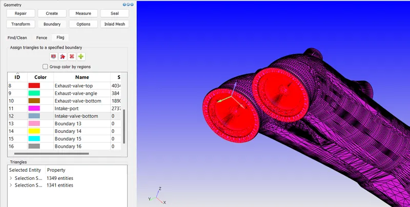
Creating fences for inlet top valves
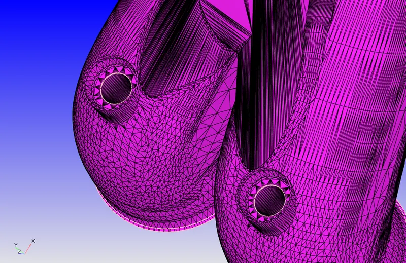
Assigning boundary using boundary fence selection
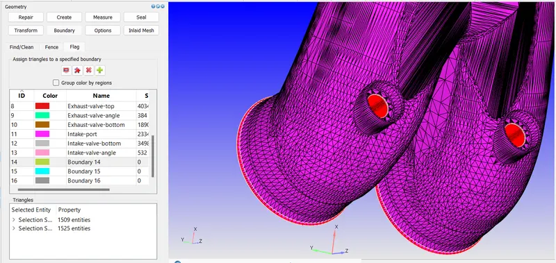
Now to remove the intersection errors in the model we measure the arc normals for the top valve as follows
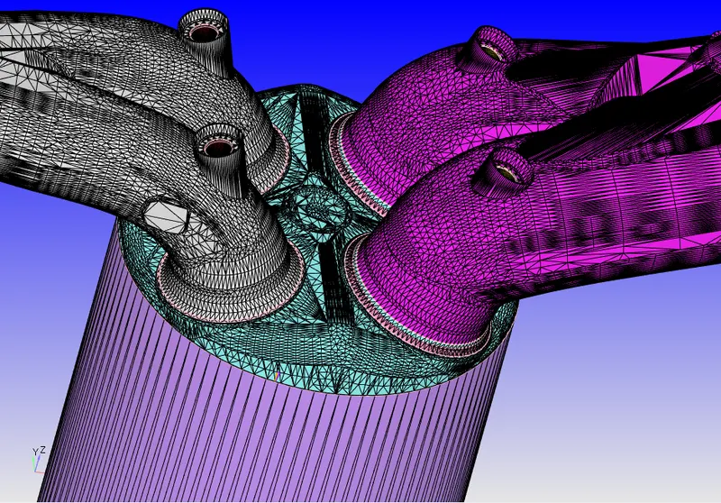
Measure>direction>arc normal and selecting any 3 points on same circle
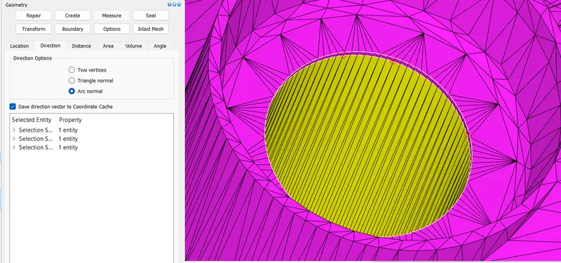
we get data as
Arc normal: -3.0901518226896E-01 2.0109789762413E-05 -9.5105710486957E-01
using this to translate the intersecting surfaces as follows
Transform>Translate>using selected boundaries and use Arc normal as dimensions with 1mm translation and selecting the intake valve angle, bottom and top and applying
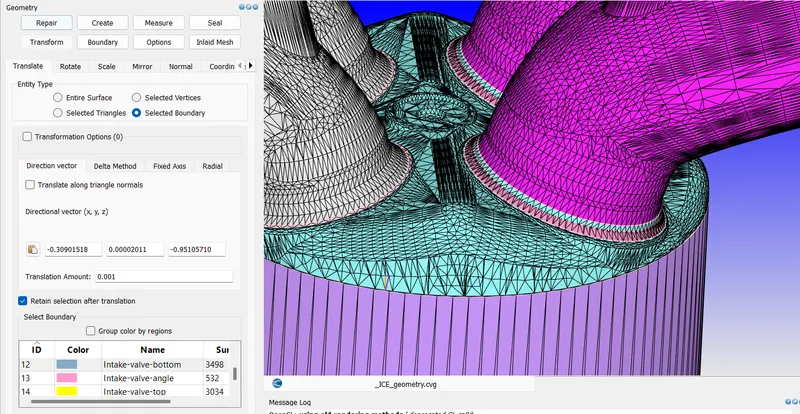
After translation
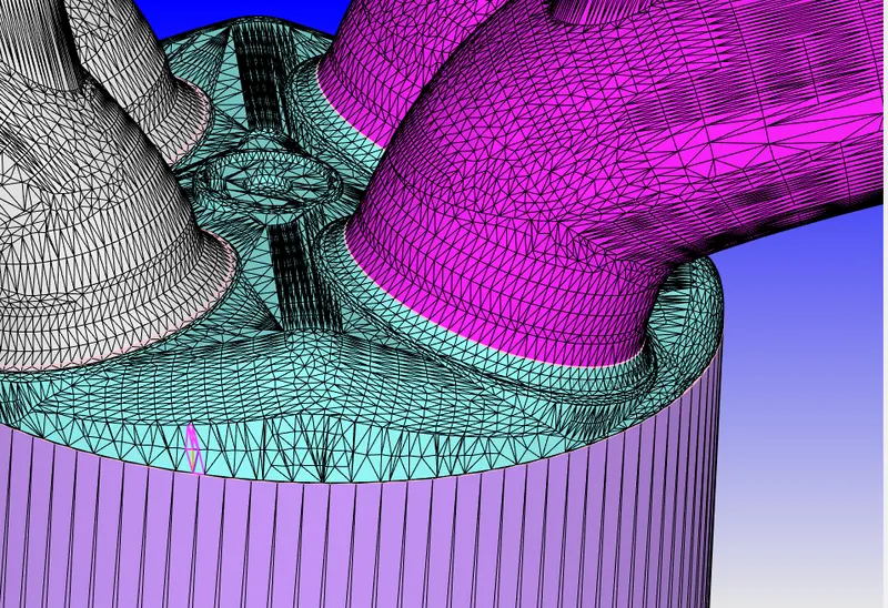
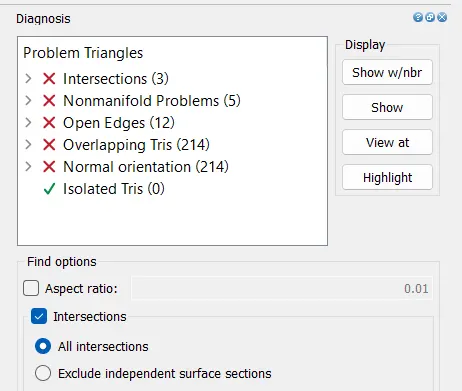
Now doing diagnosis we see most intersection errors are fixed
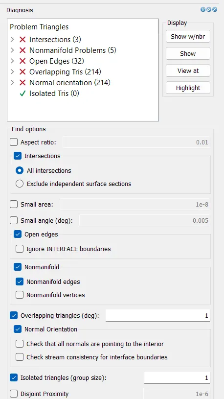
Then fixing the open edges using Patch>open edge selection with apply boundary accordingly for new triangles
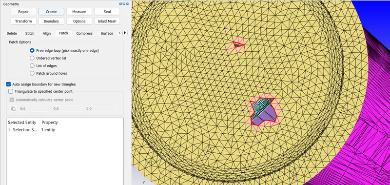
Now open edges are reduced and fixing other open edges
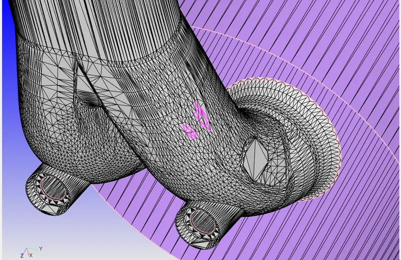
Patching the open edge
Deleting the overlap triangles and using vertex selection mode to stitch
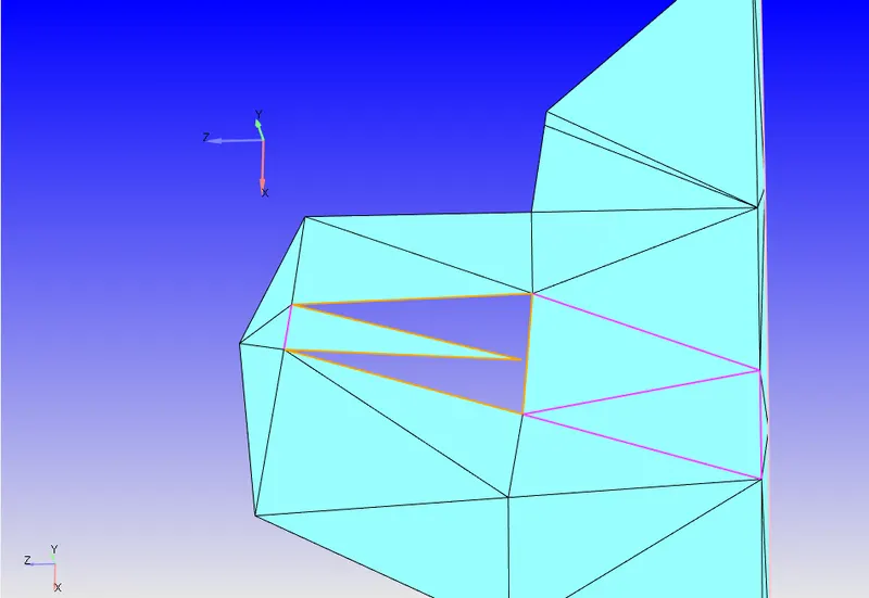
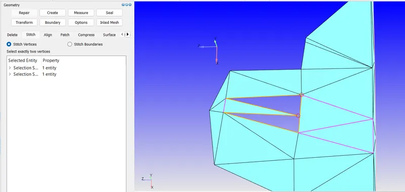
After stitching
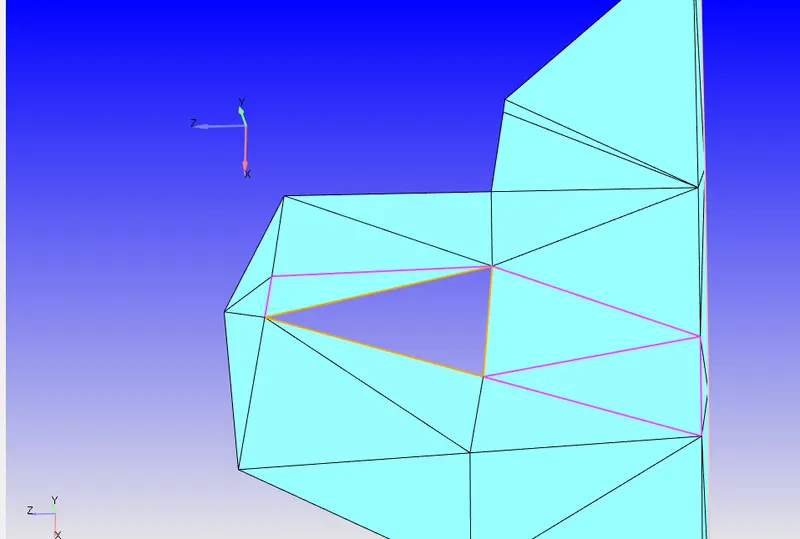
Using patch tool using open edge fixing the open traingle
Now viewing the normals and fixing them
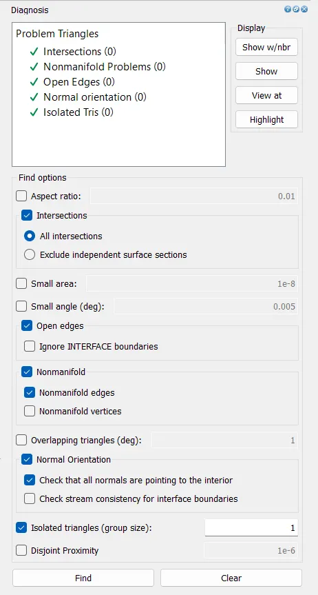
Now checking the diagnosis we see no errors
Applying boundary for spark plug terminal and spark plug
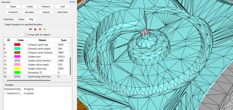
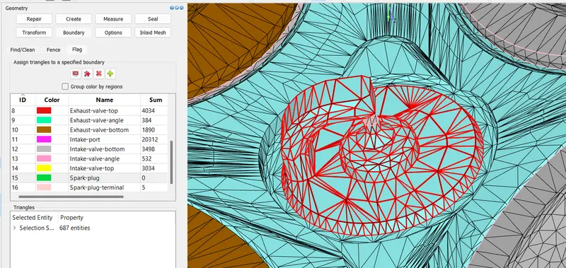
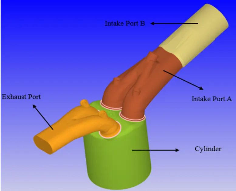
Before we move on to setup the initialization and boundary conditions we have to divide the intake port into two parts because fuel is injected through one half of the intake port and other part has no fuel spray.
To initialize the fuel that comes into the combustion chamber we split the valves into two boundaries namely intake port A (with fuel) and intake port B (without fuel)respectively as showin in figure.
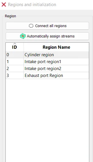
After we are done flagging above boudaries to the individual components we assign regions. A region is a closed volume. One region can interact with the other one but the interface should be clean as in image.
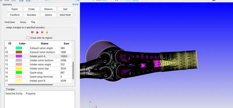
The valves interact with the intake combustion chamber and exhaust combustion chamber regions.
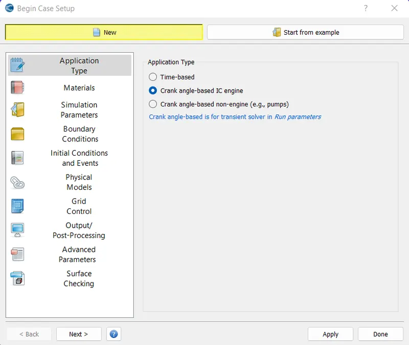
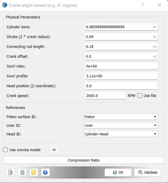
Setting up the case for Crank for IC engine for part-2 case setup of project 1
Assigning the regions as follows
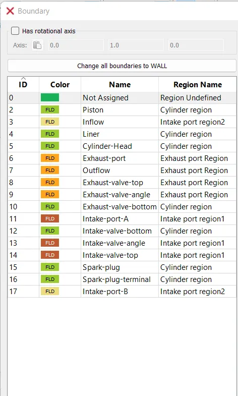
Assigning the regions to boundaries as follows
DISCONNECT TRIANGLES:
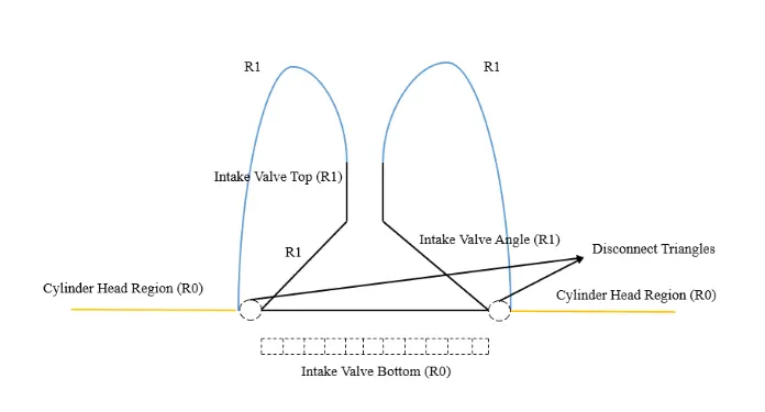
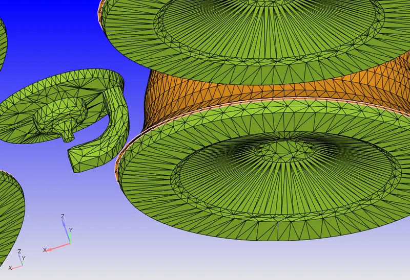
From the above figure we see two circles, which are basically called as disconnect triangles, where converge creates the triangles in that area. Thay restrict the flow which enters the cylinder region. When the triangles disappear flow is allowed by converge. If disconnect triangles are not present our valve is quite open and we would be under predicting the mass flow which enters our computational domain.
Importing exhaust file
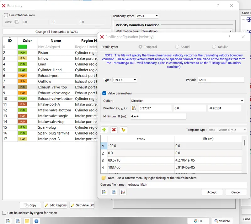
Giving minimum lift as 2e-4
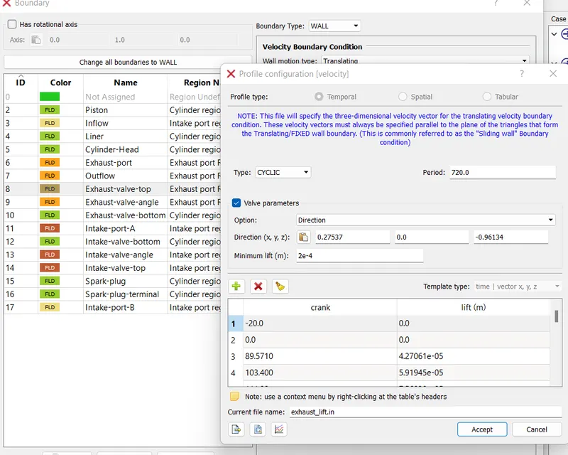
Using same file with same BC for exhaust valve angle and bottom
Now for inlet ports using files same as exhaust BC

For piston
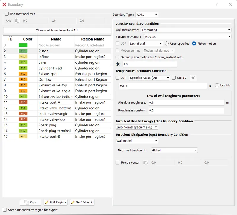
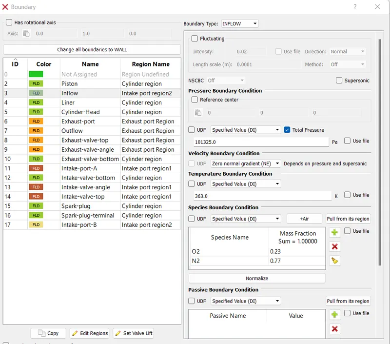
For inflow
For outflow
For all other boundaries are fixed wall boundaries with following temperatures
Liner 450K
Cylinder head 450K
Exhaust port 500K
Intake port A 425 K
Intake port B 425K
Spark plug 550K
Spark plug terminal 600K
For application type
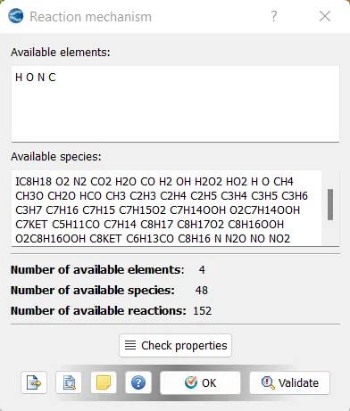
For reaction mechanism using the mech.dat file
Imporing the thermo.dat file in gas simulation
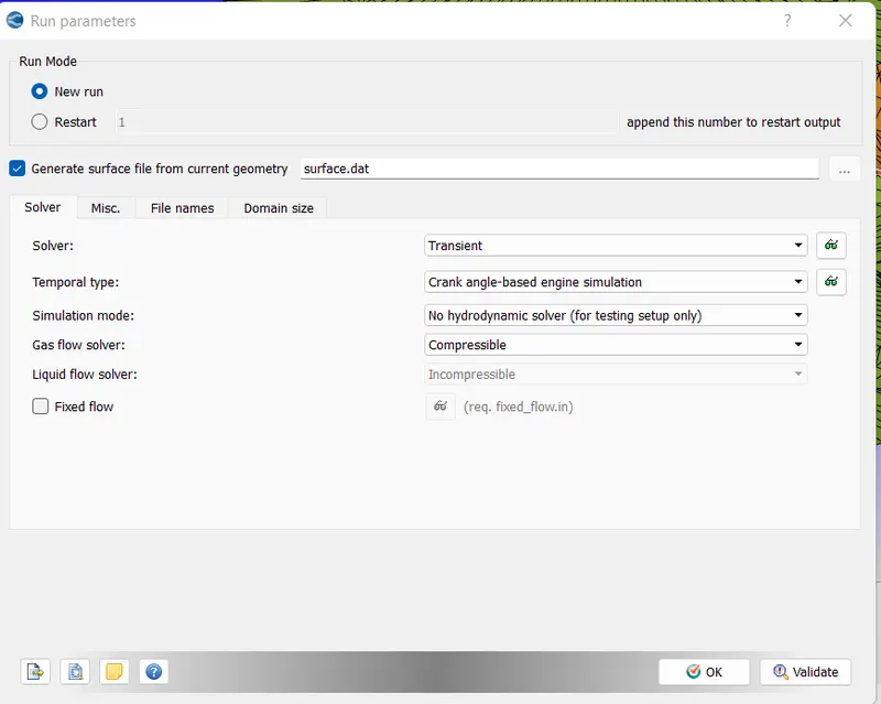
For run parameters setting for Transient and no Hydro case
As a fuel we use liquid iso octane(IC8H18)
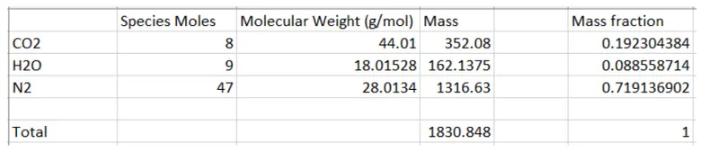
We use stoichiometric calculator
we have equation for combustion of fuel as
`C 8 H 18 + 12.5 ( O 2 + 3.76 N 2 ) = 8 C O 2 + 9 H 2 O + ( 3.76 ⋅ 12.5 ) N 2 C 8 H 18 + 12.5 ( O 2 + 3.76 N 2 ) = 8 C O 2 + 9 H 2 O + ( 3.76 ⋅ 12.5 ) N 2`
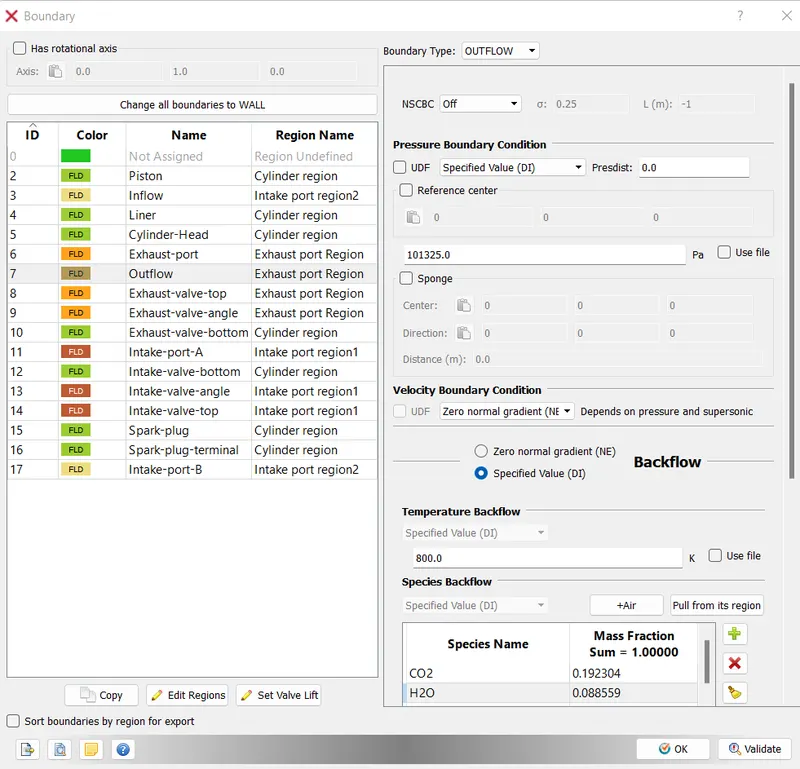
For Intake port region 1
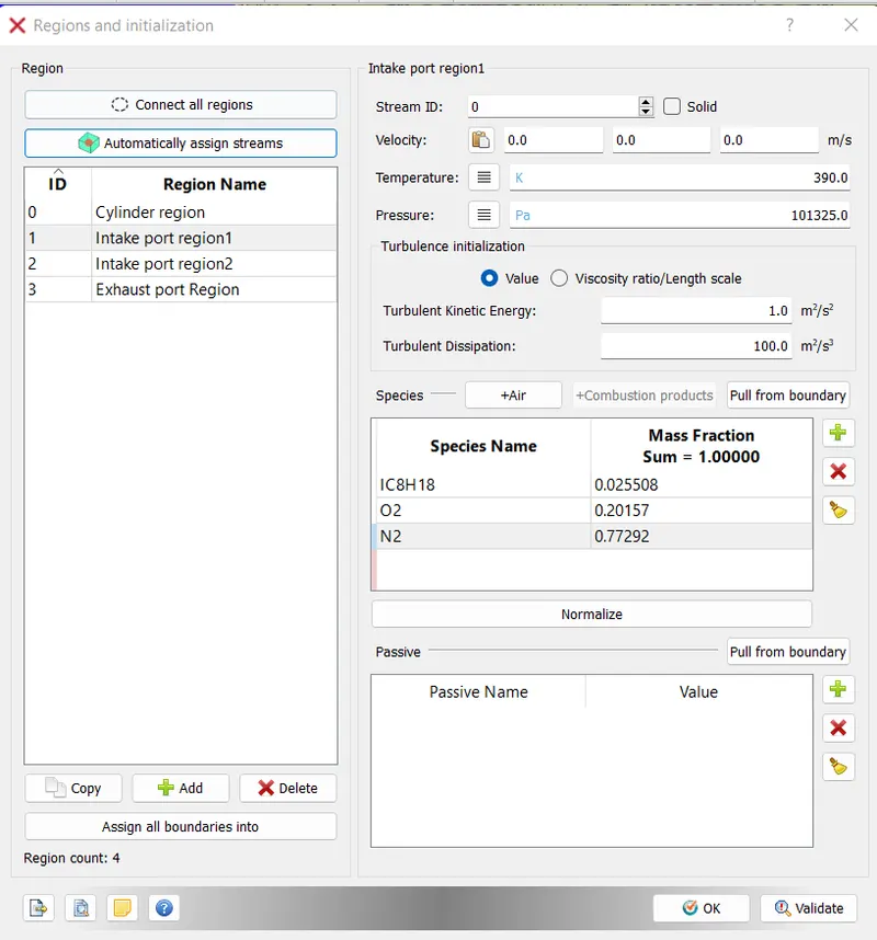
For intake port region 2
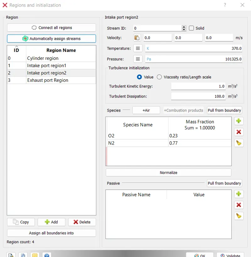
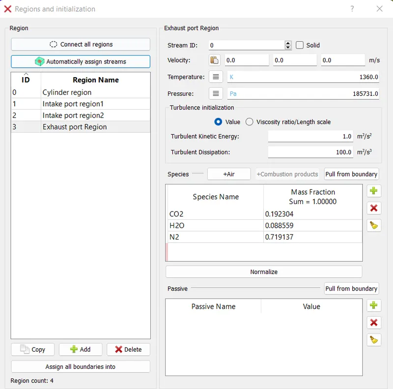
For exhaust port region
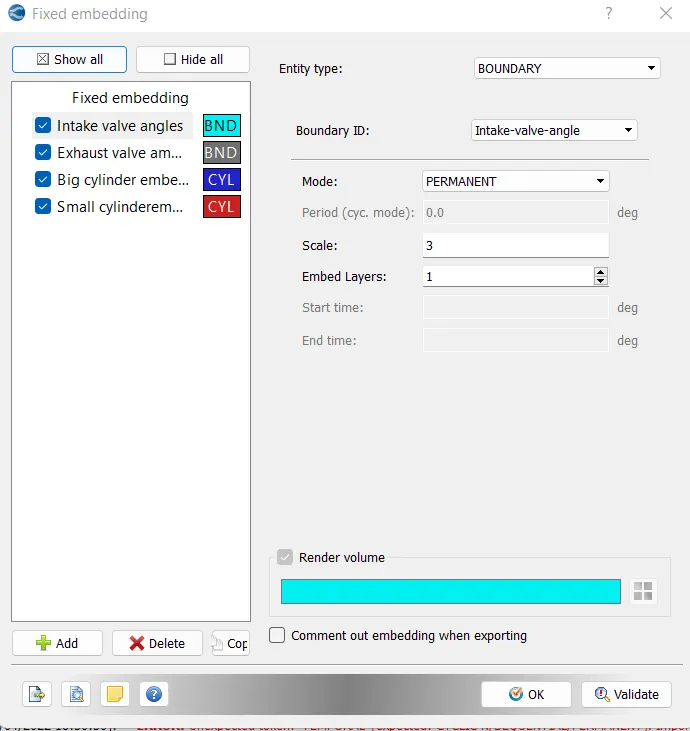
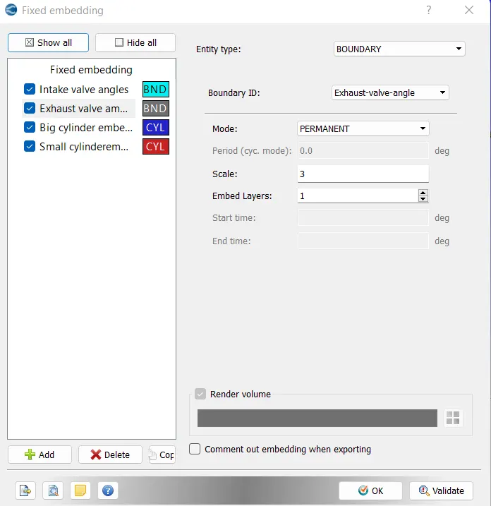
Using fixed embedding as follows for different parts
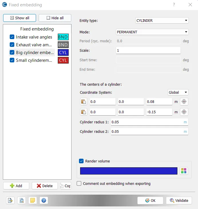
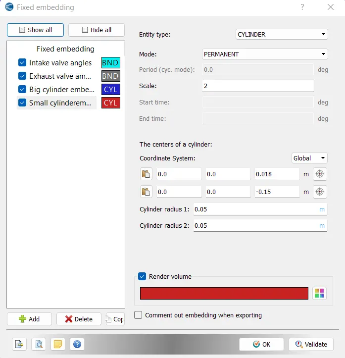
Then we continue the further part by running the case set-up simulation using Cygwin in the next challenge.
CONCLUSION:
Thus the Surface preparation and boundary flagging is completed for the Project1 part-1 case successfully.