Week -2
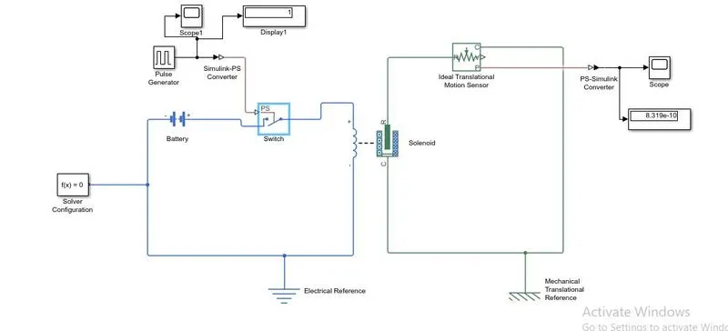
AIM: To make a simulink model of door bell using 'solenoid' block with the help of battery, switch, solenoid, ideal translational motion sensor, mechanical translational reference, electrical referenece, scope, display, PS-simulink convertor, simulink-PS convertor.
DESCIRPTION:
Here for the entire set-up of model is done by using output as pulse generator which generates the pulses in square from at regular intervals. The waveform of the pulse generator shows the Amplitude,pulse width, period and delay time as parameters as shown in the figure below
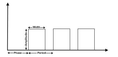
Here for the door bell to ring an electical signal is sent through the battery or the electrical medium and a pulse generator generates the waves in mechanical form due to which the bell starts to vibrate and sound is produced.
So, the for the entire set-up to work with a switch with 2seconds closed a pulse generator is given parameters as follows:
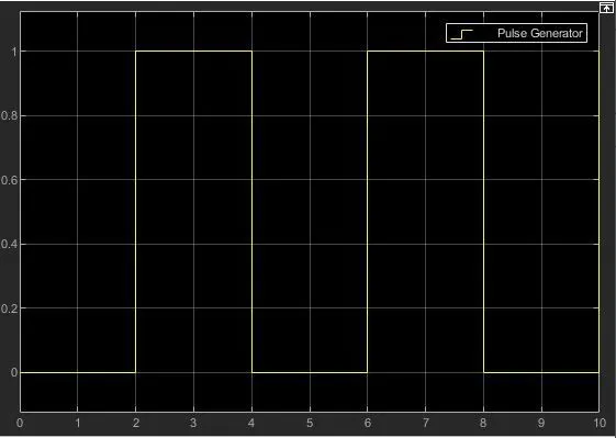
Period value=4sec
pulse width=50% of the period
phase delay=2sec
Amplitude as default=1sec
The above parameters of the pulse generator states that as phase delay is given as 2sec so initially the pulse will be zero, then the pulse will start from 0 to 1. As amplitude is given as 1, for the first 2seconds the pulse will be at amplitude 1 and then for next 2sec it will be at 0 amplitude at4sec, thus a period is completed.
BLOCKS USED:-
1.Pulse generator
2.solenoid
3.scope
4.display
4.electrical reference
5.mechanical translational reference
6.battery
7.switch
8.ideal translational motion sensor
9.solver configuration
10.PS-simulink convertor
11.Simulink-PS convertor
MODEL:
OUTPUTS:
Graph for pulse generator is as follows:
Graph for Ideal translational motion plunger is as follows:
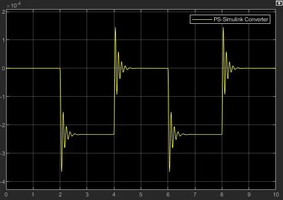
from the above graphs we come to know that at aplitude for 1 for every 2seconds there are waves generated by the plunger.
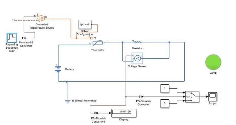
AIM: To make a model with use of thermistor to sense the temperature of a heater & turn ON or turn OFF the fan as per the conditions:
CONDITIONS:
Temperature source : 20 celsius from 0 to 10seconds, 27 celsius from 10 to 30 seconds, 23 celsius from 30 to 50 seconds
Fan Conditions: ON if temperature above 25 celsius, OFF otherwise.
DESCIRPTION:
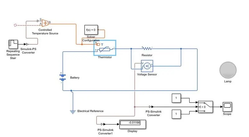
The repeating sequence stair is used as input to the temperature controlled source for the thermistor.
The sample time is taken as 10sec and the simulation time as 50seconds.
A Resistor is connected to the thermistor along with the voltage sensor and Battery, for the sensor to measure the change in voltage at different temperature inputs.
Resistor is set to default as usual. Treshold temperature is taken as 25 celsius for the switch.
If the lamp changes to green that means it states that the temperature is greater than 298K or 25celsius
BLOCKS USED:
1.Controlled temperature source
2.Repeating sequence stair
3.scope
4.display
4.electrical reference
5.Thermistor
6.battery
7.switch
8.Voltage sensor
9.solver configuration
10.PS-simulink convertor
11.Simulink-PS convertor
12. Resistor
OUTPUTS:
When the temperature is above 298K the lamp shows green which means fan must be switched ON