Week 9: Project 1 - Surface preparation and Boundary Flagging (PFI)
Name of Project: -Surface Preparation and Boundary Flagging ( No hydro Simulation)
Objective:
- Perform surface preparation and boundary flagging tasks on our IC Engine case and setup a No Hydro Simulation
Introduction –
Surface preparation and boundary flagging is important steps before we go case setup. These terms are related to converge software only, in CFD domain we can call surface preparation as geometry clean-up. In simple language, surface preparation is process to detect the error in CAD model and solve the them, if one goes negligence, he will definitely end simulation with wrong results. Boundary flagging is a procedure in which we assign the suitable names to the boundaries, because CFD software does not have intelligence to do the same.
Port fuel injection refers to the system where the fuel is injected in inlet manifold of the engine. The fuel mixes with the air thoroughly because there is lot of time to mix fuel with air, during intake and compression stroke, fuel is mixed with air.
Surface preparation and boundary flagging are major step to begin any simulation, one has to be very careful about these steps, otherwise it will ruin the simulation. In this section we will see the major types of error and their diagnosis, specific to converge software only. Converge automatically highlights the errors by magenta colour, after error check, but have to look at the reason behind the errors then only we can remove them.
Intersections – As the name suggest that intersection of the plane of one triangle to another plane of triangles. Areas and angles less than specified values will be also considered as intersection error. Intersection error can be removed by translating or rotating the surfaces or increasing the angle or areas, if any.
Nonmanifold Problems – Nonmanifold Problems arises when an edge that is shared by more than two triangles or A vertex that connects two otherwise disconnected pieces of geometry. This is error will be removed automatically after assigning the boundaries or regions.
Open Edges – this problem arises when there is an open edge, since converge works on the volume so it’s does not allow open edges. Make patch or stitch triangles to remove this error.
Overlapping triangles -Triangles that meet other triangles at an angle less than the specified value, in degrees. Delete the overlapping triangle and make patch if necessary.
Normal orientation – this problem arises a triangle have different orientation of normal than its adjacent one. This error can be removed easily by translating the normal.
Procedure:
Initially import the geometry in the converge
Then go to diagnosis and check the error in this geometry
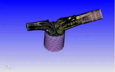
Note: in this geometry file there is lot of errors so we must flag the boundary clear all error and then go to simulation
Boundary flagging:
- Flag the boundary
- Boundary flagging helps us to cleaning the geometry easily
- In order to create the flagging, the geometry choose path: - Geometry – Boundary -flag – and create required boundaries (used required boundaries definition)
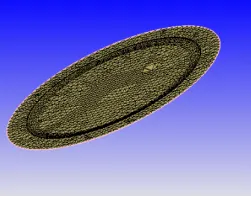
Piston:
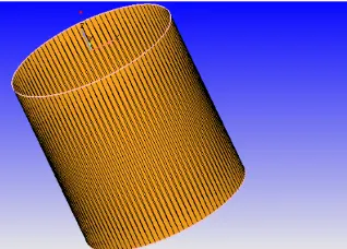
Liner (Cylinder Liner):
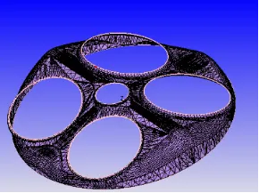
Cylinder head:
Exhaust port
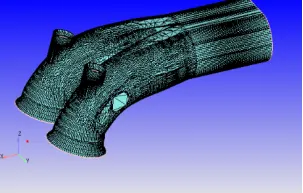
Intake port
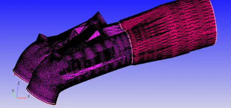
Spark plug
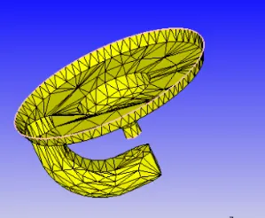
Total Case Setup
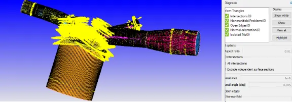
Errors in geometry
Open Edges: - patches were created to solve this problem. Repair>Patch>Free edge loop
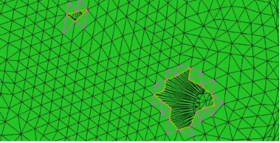
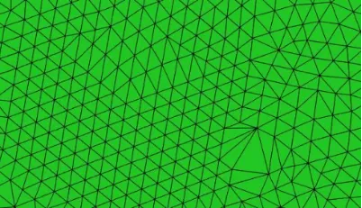
Non-manifold problems - Extra triangles deleted first and then patches were created.
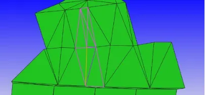
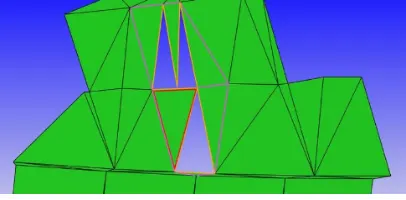
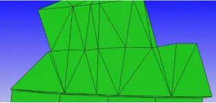
Check the diagnosis

And then Move Towards Case set up
Case Setup
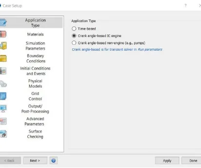
the case setup we started with crank angles-based IC engine as application type.
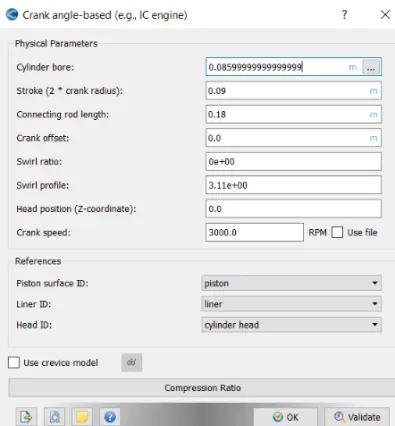
In gas simulation parameter therm.dat file was imported which contains gas thermodynamic data specifically related to IC engine.
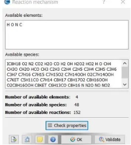
In reaction mechanism windows properties were checked to see the available species, which were imported by therm.dat file.
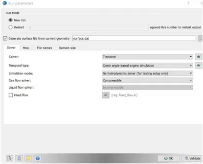
In run parameter transient was chosen as solver type with no hydrodynamic simulation mode, because we wanted to see mesh movement only without the effect of fluid
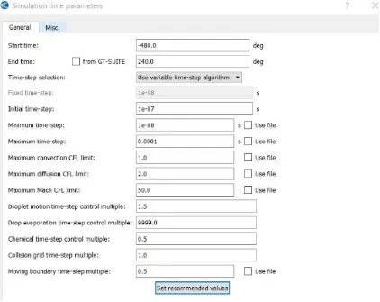
Total 16 boundaries Were Flagged
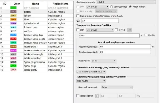
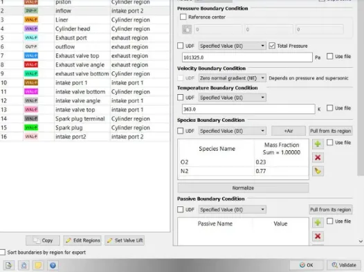
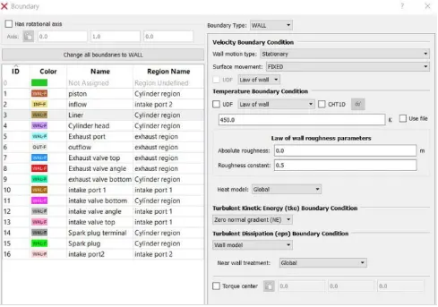
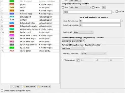
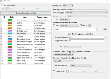
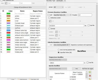
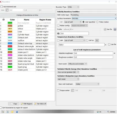
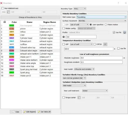
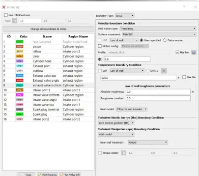
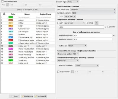
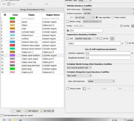
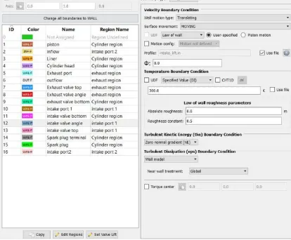
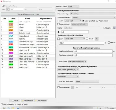
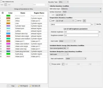
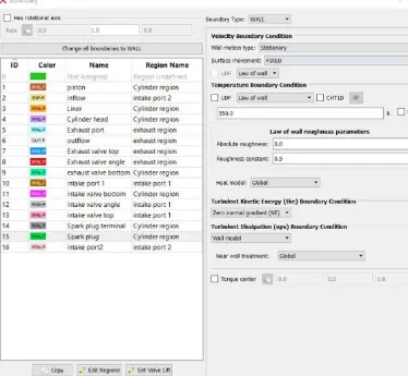
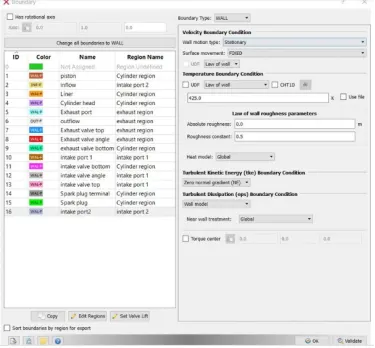
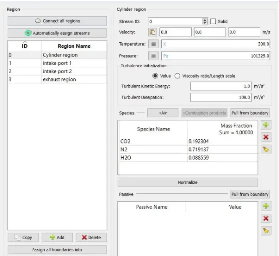
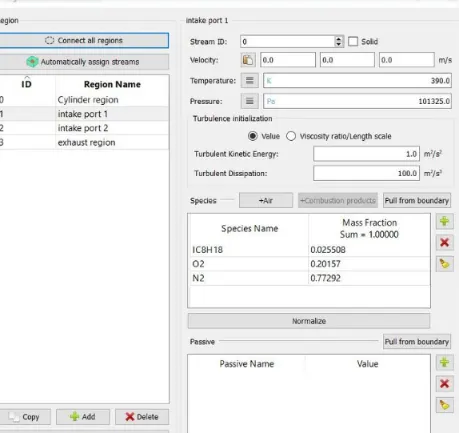
Four major regions were defined named cylinder region, intake port1, intake port2 and exhaust region. Region allows us to defined region-specific properties like exhaust and inlet region can not have same properties
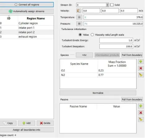
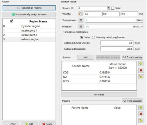
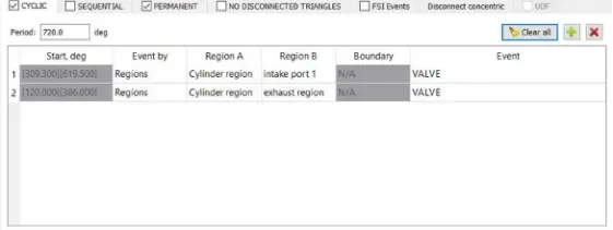
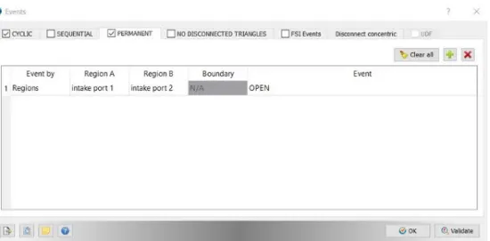
Event were enabled in initial conditions and even option and we specified three events, two were cyclic which would replicate valve movement and one event was permanent which specified no barrier between intake port 1 and intake port 2.
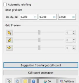
chose k-epsilon turbulent model and base grid was chosen as 0.008m because we were performing no hydrodynamic simulation and these parameter does not have any effect on simulation.
Base Grid
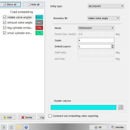
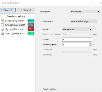
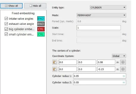
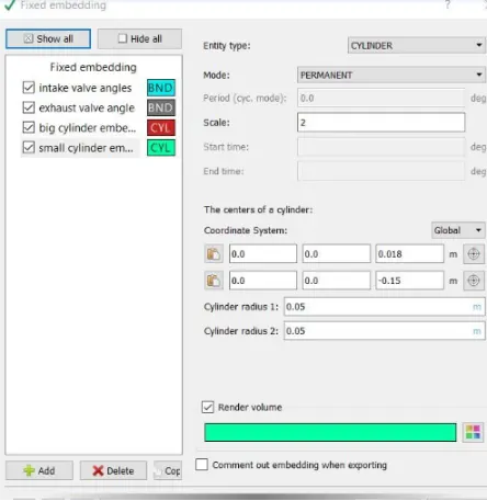
Fixed Embedding
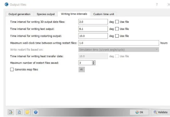
Output files
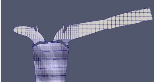
Results And Contours
Mesh Contour
At time Step = 100
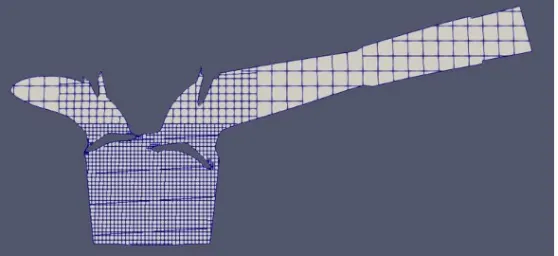
At time Step = 150
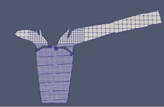
At time Step = 300
Conclusions: -
1.Surface Preparation and Boundary Flagging is successfully Done
Animation link:-https://www.youtube.com/watch?v=O4-k8ii_rCM&t=10s