Week 9: Project 1 - Surface preparation and Boundary Flagging (PFI)
Aim: - To setup a No-Hydro simulation on an IC engine.
Objective: -
- To prepare the surface and flag the boundary.
- To setup a no-hydro case and create an animation for the same and mesh with respect to time.
Introduction: -
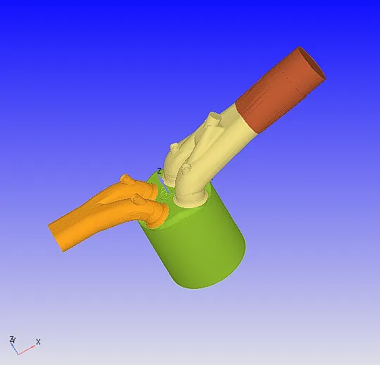
Model of IC engine –
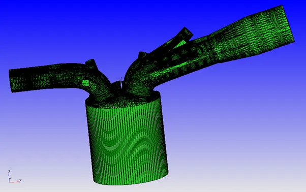
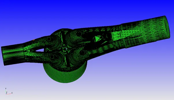
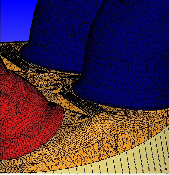
Diagnosing the model following problems are encountered
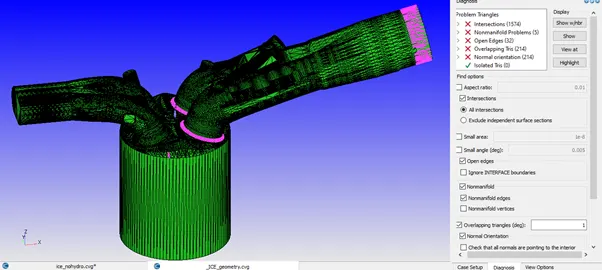
Steps to clean and prepare the geometry
- Normal orientation is flipped for one triangle and propagated using transform tab in geometry dock. Normal orientation is resolved along with few overlapping triangles.
- Open edges are patched and overlapping triangles are deleted.
- Intersection triangles are due to valve intersecting the port. To remove this Valves are flagged and translated along the normal of the valve.
During the flagging of valves and ports the ring triangles should belong to the non-translating boundary to avoid alignment error.
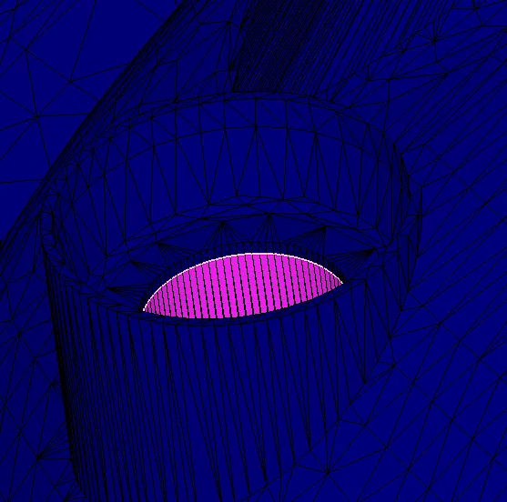
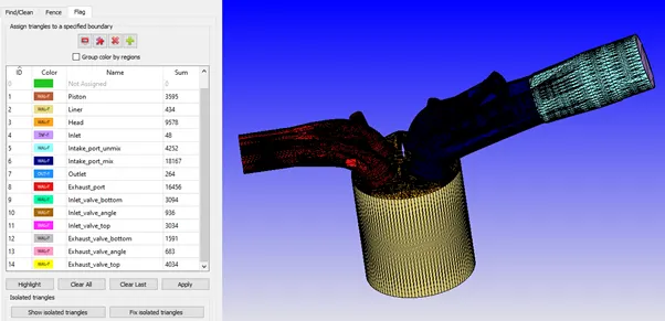
The boundary at intake port and cylinder should be appropriate to avoid alignment error due to disconnect triangles.
Boundary –
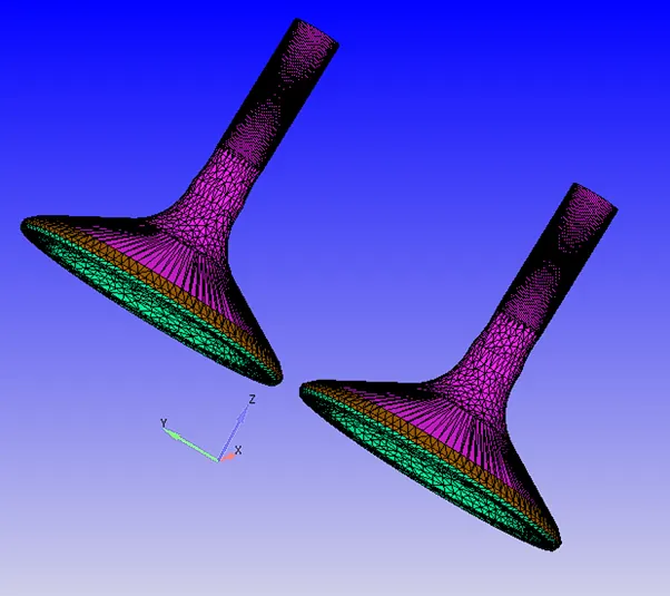
Inlet Valve flags-
Exhaust Valve flags –
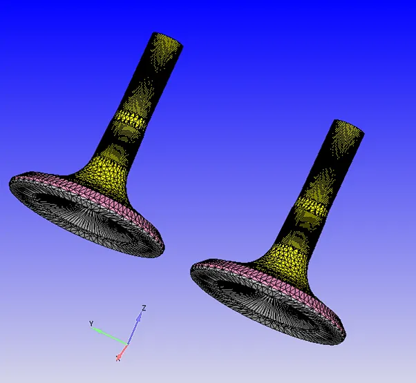
Valves are divided into 3 parts namely – Top, angle and Bottom as different boundary of the valve belongs to different regions and for putting mesh refinements on angle boundary.
Case Setup: -
- Application Type- Crank angle-based IC engine.
- Gas simulation with along with Parcel simulation and Air as predefined mixture.
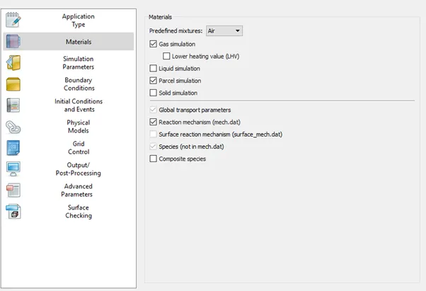
- IC8H18 is selected from predefined liquid in Parcel simulation.
- Density Based Transient State Solver is used with Compressible Gas Flow solver and Incompressible liquid Flow solver with no hydrodynamic simulation and PISO Navier-Stokes’s solver scheme.
- The solution run for -480 deg to 240 deg which is 720 deg cycle.
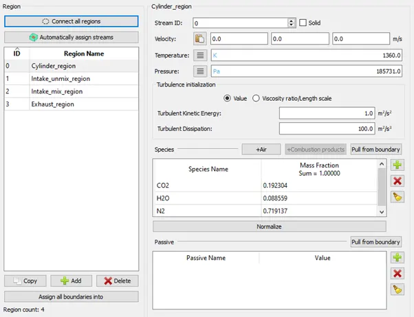
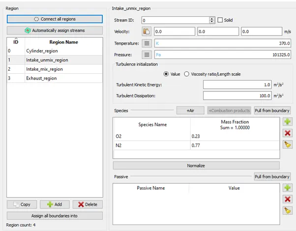
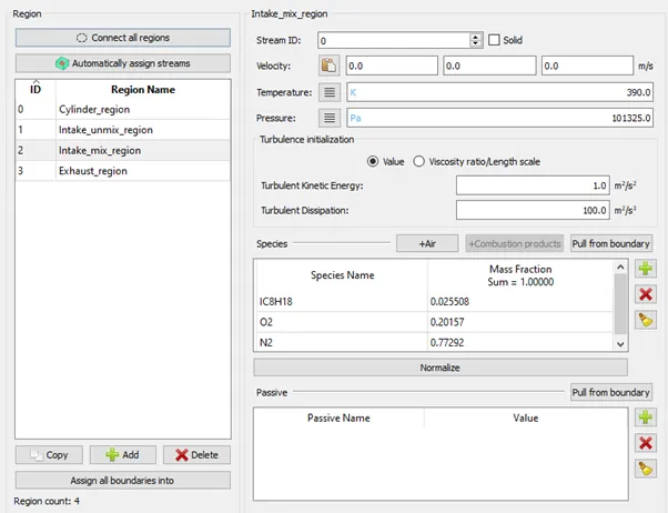
- Regions –
Cylinder Region:
Intake_unmix_region:
Intake_mix_region:
Exhaust_region:
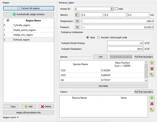
Regional group –
- Boundary Condition:
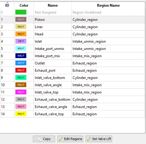
Region Allocation –
|
Boundary |
Region |
Boundary Condition/ Motion |
Temp (K) |
Species |
|
Inlet |
Intake_unmix_region |
Inflow |
363 K |
O2: 0.23 N2: 77 |
|
Intake_port_Unmix |
wall Stationary |
425 K |
||
|
Intake_port_mix |
Intake_mix_region |
wall Stationary |
425 K |
|
|
Inlet_valve_top |
wall Translating |
480 K |
||
|
Inlet_valve_angle |
wall Translating |
480 K |
||
|
Inlet_valve_bottom |
Cylinder_region |
wall Translating |
480 K |
|
|
Head |
wall Stationary |
450 K |
||
|
Liner |
wall Stationary |
450 K |
||
|
Piston |
wall Piston Motion |
450 K |
||
|
Exhaust_valve_bottom |
wall Translating |
525 K |
||
|
Exhaust_valve_angle |
Exhaust_region |
wall Translating |
525 K |
|
|
Exhaust_valve_top |
wall Translating |
525 K |
||
|
Exhaust_port |
wall Translating |
500 K |
||
|
Outlet |
Outflow |
800 K |
CO2: 0.1932 H2O: 0.088525 N2:0.71913 |
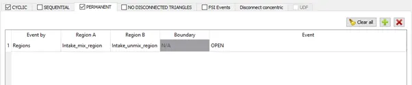
- Event is marked in initial condition and events tab.
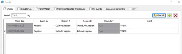
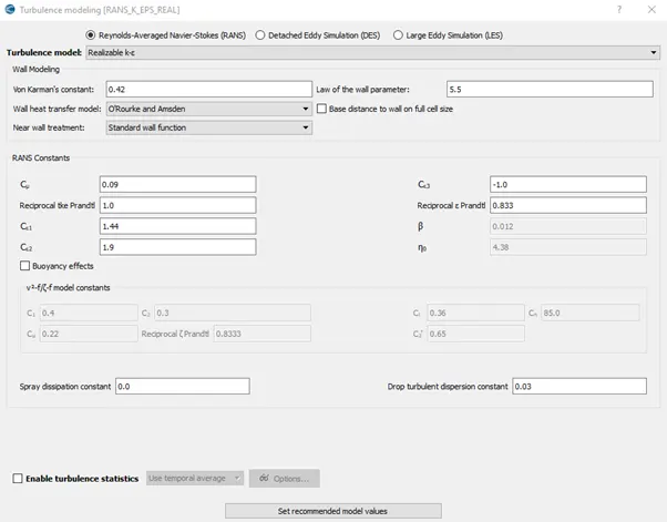
- Realizable K-epsilon is used for turbulence modelling with recommended values.
- Base grids of 0.005 m or other for respective cases are generated for all axis.
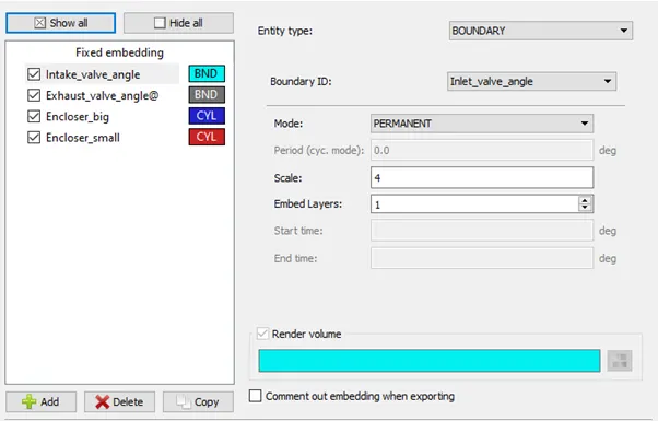
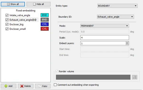
- Fixed Embedding is marked in grid control tab and 4 embedding are added.
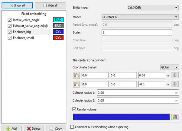
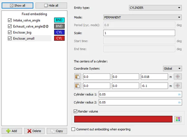
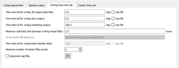
- 3D output data is written after every 4 deg.
- The input files are exported to a folder to further solving.
Solving using Cygwin:
The Cygwin directory is navigated to the above saved folder and following code is entered to solve the problem.
mpiexec.exe -n 2 "C:\Program Files\Convergent_Science\CONVERGE\3.0.16\bin\intelmpi\converge.exe" restricted </dev/null> logfile &
where address in quotes gives the path of folder containing input file exported earlier.
Post-Processing:
Post-Processing is done with the help of Converge CFD post processing tab –
The output 3D data is converted in ‘. vtm’ file and contours and animations are prepared though ParaView.
Results:
Initial Mesh –
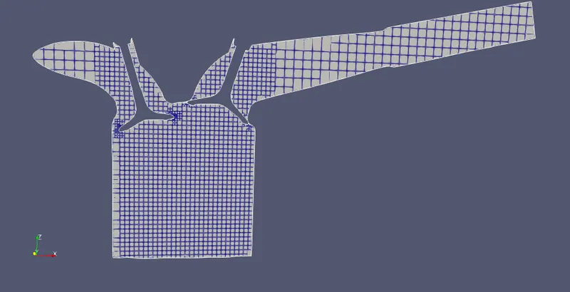
Mesh Animation-
No-hydro animation