Week 9: Project 1 - Surface preparation and Boundary Flagging (PFI)
Aim-To simulate the no hydro of the port fuel injection.
Objectives-1.To carry out the surface preparation of the PFI
2.To carry out the Bounadry flagging of the PFi.
3.To run the no hydro simulation of the PFI.
Theroy-
In this Project we are carrying out No hydro simualtion of the Port fuel injection, In no hydro simulation the reaction is not involved we need to check only the meshing part of the pfi and the movement of the parts.Before carrying out the simulation First we need to flag boundarires to get free from the surface errors.
Boundary Flagging-Flagging is done to seperate the parts from one another and to identify the parts.The parts seperated from one another by creating the fence.
The imported geometry is as shown below which need to be flagged
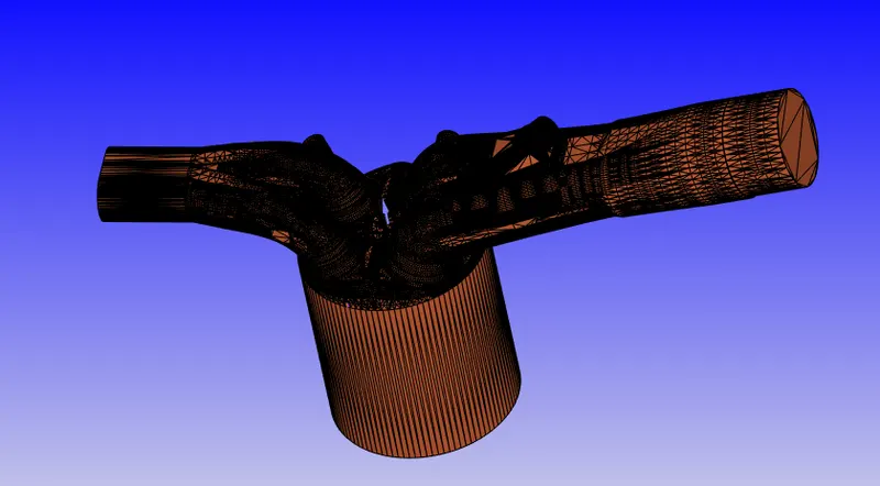
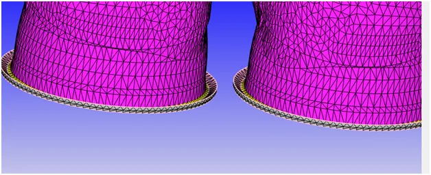
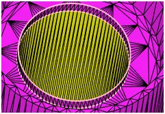
when we want to flag the lining of the cyclinder its going tp select the whole geometry which is not required hence we create fence around the cyclinder head and at the bottom of cyclinder .so the cyclinder get isolated.The fence is marked in the white colour.
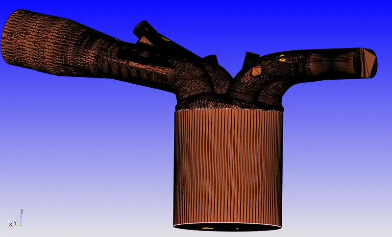
when we want to flag the the cyclinder head when we select its going to select the cyclinder head,intake valve and exhaust valve hence in order to isolate the cyclinder head frm the two valves hence we create fence aornd the two valves.
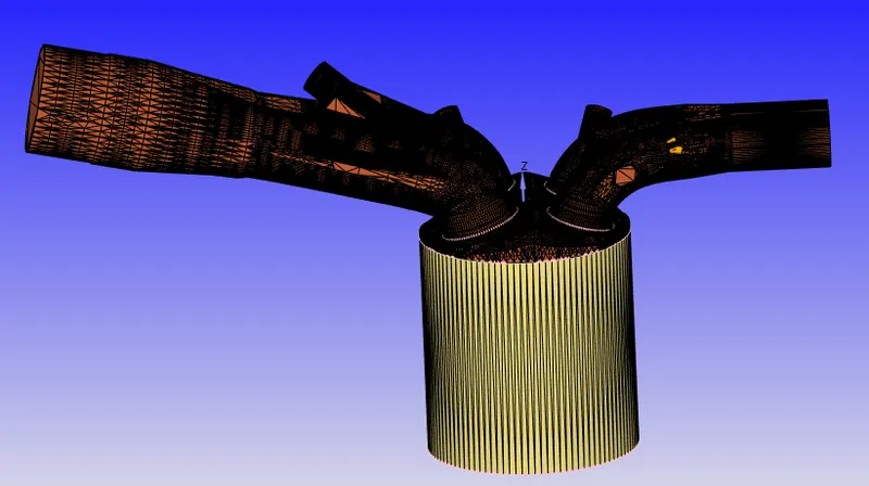
the below figure shows the exhaust valve of thePFI from figure we need to isolate the exhuast bottom ,exhaust valve angle and exhaust top hence we need to create fence
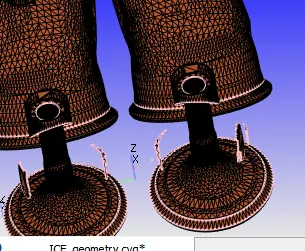
similarly we can isolate inletport top valve,inlet top bottom and inlet valve by creating the fence.
Surface preparation-
when we imort the cad stl file we are going to get some errors such as
1.Intersection error
2.Noimanflod
3.Open edges
4.Normal orientations
1.Intersection-the most of the errors due to intersection this is due to of intersecting triangle og the inlet port with cyclinder triangle to aviod this error we have to translate the inlet valve angle,inlet top valve valve and inlet bottom boundaries by amount of 0.001 in the direction of the measured normal.
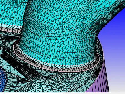
the above error resloved by translating the the inlet bottom ,inlet top valve and inlet valve boundaries by amount of 0.001 in the direction of the measured normal.
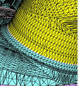
fig- after translating we resloved the intersection error.
2.Nomanfold problem and overlaping-This error occurs when single edge shared by more than the two triagles then that edge is called Nomanifold edge.
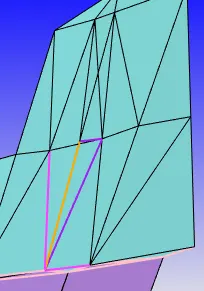
To reslove this problem we delete the over laping triangles.
3.open edge-To select open edges go to triaglkes and select by open edge and patch them.
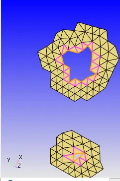
case set up-
Application type Crank anble based Ic engine
materials:
gas simulation; import therm.dat file
Reactiom Mechanism; import mech.dat
Run parameters:no Hydrodynamic solver
simulation time parameters
Boundary condtion-
|
Boundary |
Type |
Wall motion |
Surface movement |
Temperature |
Pressure |
|
piston |
wall |
Translating |
Moving |
450 |
- |
|
Lining |
wall |
stationary |
Fixed |
450 |
- |
|
Cyclinder Head |
wall |
stationary |
Fixed |
450 |
- |
|
Inlet |
inflow |
stationary |
Fixed |
363 |
101325 |
|
Exhaust port |
wall |
stationary |
Fixed |
500 |
- |
|
Exhaust top |
wall |
Translating |
Exhaust lift.in |
525 |
- |
|
Exhaust bottom |
wall |
Translating |
Exhaust lift.in |
525 |
- |
|
Exhaust angle |
wall |
Translating |
Exhaust lift.in |
525 |
- |
|
Inlet port 2 |
wall |
stationary |
Fixed |
425 |
- |
|
inlet bottom |
wall |
Translating |
intake lift.in 480 - |
|
inlet angle |
wall |
Translating |
intake lift.in 480 - |
|
inlet Top valve |
wall |
Translating |
intake lift.in 480 - |
|
Spark plug |
wall |
statinoary |
Fixed 550 - |
|
spark terminal |
wall |
stationary |
Fixed 550 - |
|
inlet port1 |
wall |
stationary |
Fixed |
390 |
- |
|
Exhaust port outlet |
outflow |
stationary |
Fixed 800 |
101325 |
spieces for outflow
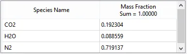
and we choose mesh grid of 4mm as the base grid size.
we have done fixed for the boundaries
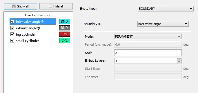
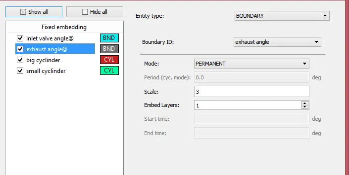
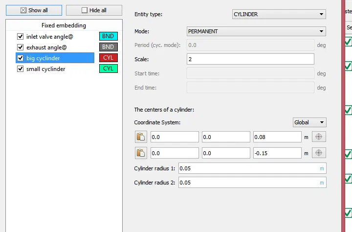
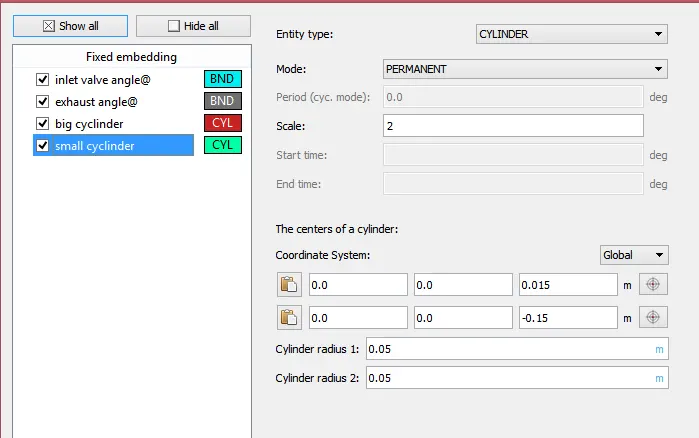
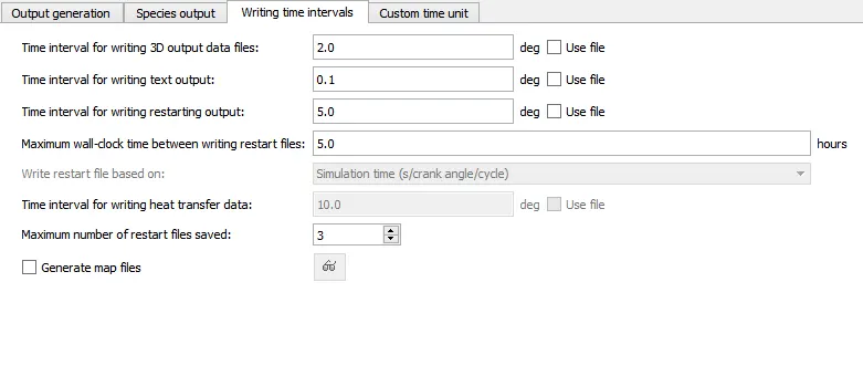
and we have output file as
link :
https://youtu.be/e85imZF-p80
sa