Week 9 - Project 1 - Door Trim Lower with Engineering Features
Draft angle: The degree of taper of the side wall of the mold or the angle of clearance designed to aid the removal of a part from a mold.
Most of the parts have a draft angle of min 3, but while designing we follow the general thumb rule of 1-degree draft per 1-inch depth.
Draft angle is provided along the TOOLING AXIS.
Tooling Axis: It is the direction in which the core and cavity of the mold move for the removal of the component inside it.
Creation of Tooling Axis Using Bisecting Method:
- First, inspect the given CLASS A surface. Use the join feature to check whether the surface has a continuous boundary or not.
- Then check the direction in which the component can be easily molded without any complications.
- Now take a plane and intersect the plane with the surface to get the curves.
- Switch to the sketcher workbench and create lines along the curves that are tilted to the dummy axis we have created.
- Bisect those lines to get a real TOOLING AXIS.
- Check if there are any other surfaces and repeat the process to get a Tooling Axis.
- Then bisect both axes to get Real Tooling AXIS.
Draft Analysis Using Tooling Axis:
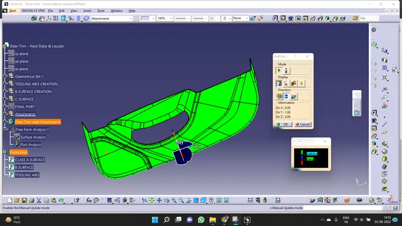
- After generating the Tooling Axis of the given CLASS A surface, insert the feature draft analysis from the analysis toolbox.
- Drag the axis system and try to align along the Tooling Axis.
- We observe the Draft analysis box that contains the mode, display, direction, and information of the tooling axis.
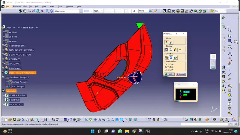
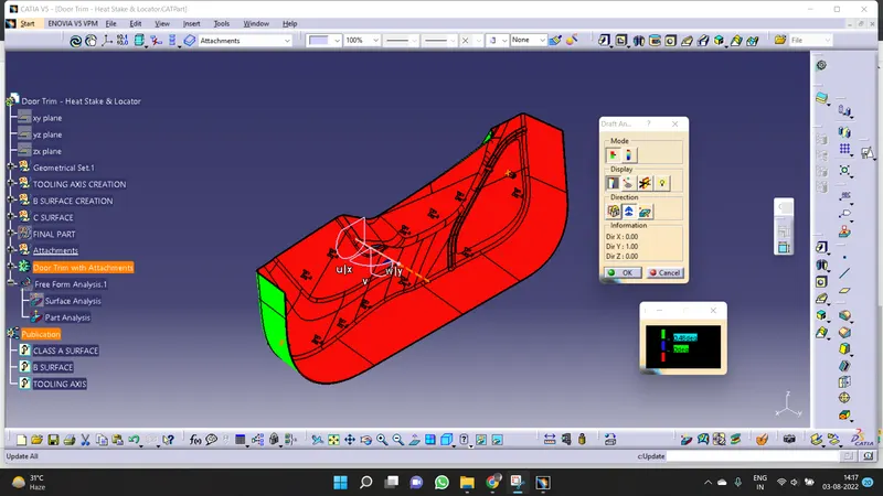
- Using the Draft analysis box complete draft analysis is performed and different draft angles are coded in different colors.
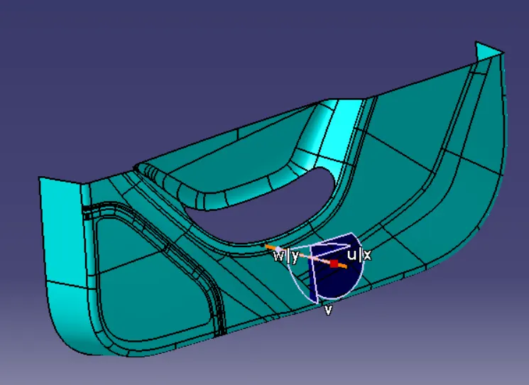
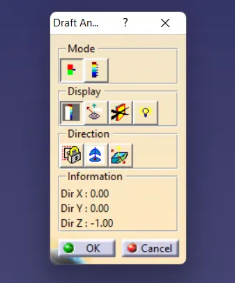
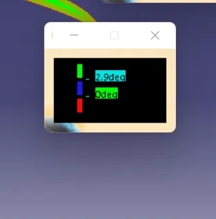
For surface and part without attachments, perform a Draft analysis with a draft angle of 2.9 degrees.
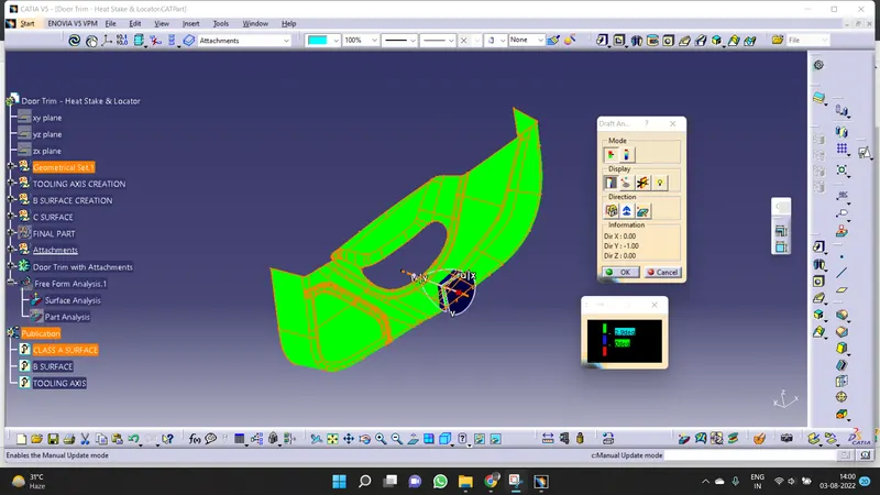
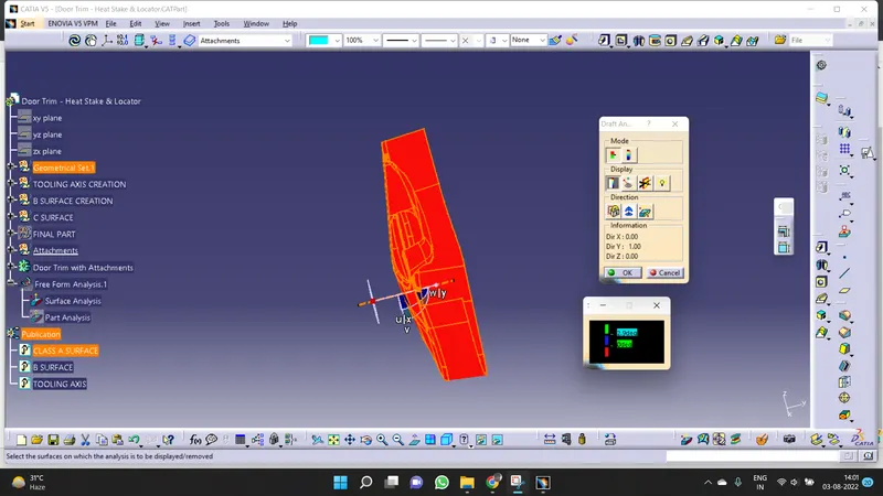
Draft Analysis Of The Final Part:
- Create the Heat Stakes and 4 Way Locators and fix them at the given points on the part.
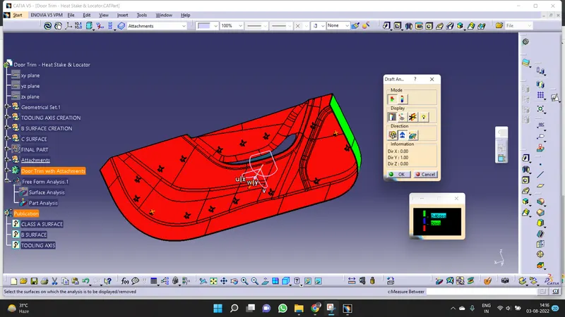
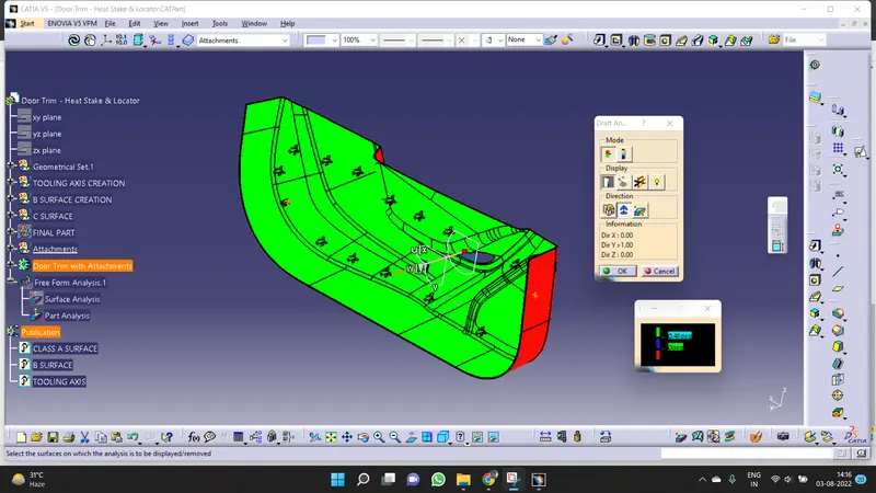
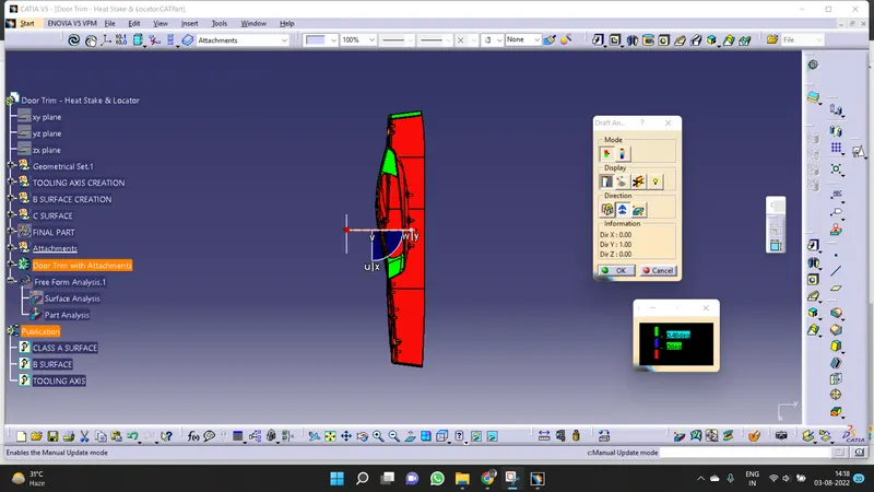
- After Creating a body with attachments, now perform a Draft analysis on the final part with a draft angle of 0.48 degrees.
- As we provided a minimum draft of 0.5 degrees to the Heat Stakes and 4 Way Locators.
- In the final part, we observe 2 color codes Red and Green.
- These color codes change along with the change in orientation of the axis system.
- We observe that Heat stakes and 4 Way locators are clearing the Draft with the B surface of the part body.