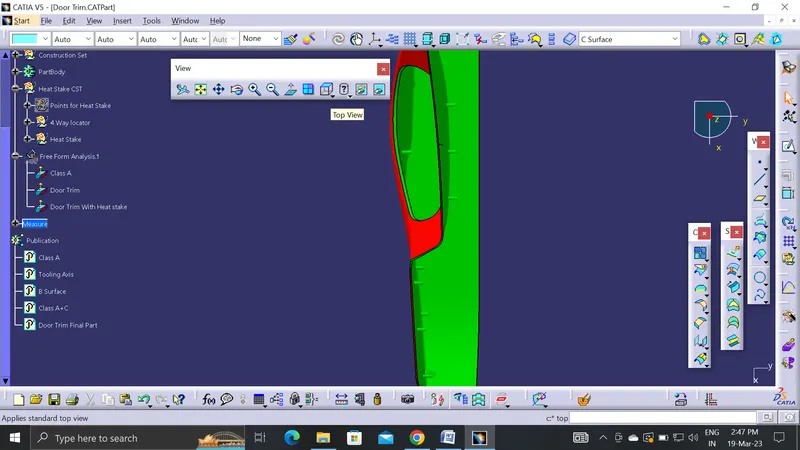
Week 9 - Project_1 - Door Trim Lower with Engineering Features
Draft Analysis
Draft Analysis is used to analyse whether given product model is manufacturable or not. There is at least some minimum Draft angle should given for each and every product, so that the mould and part making minimum point of contact when the ejection time. It also reduces the part getting affected by the mould.
Here is the complete list of steps involved in Draft analysis for given model.
Class A Surface:
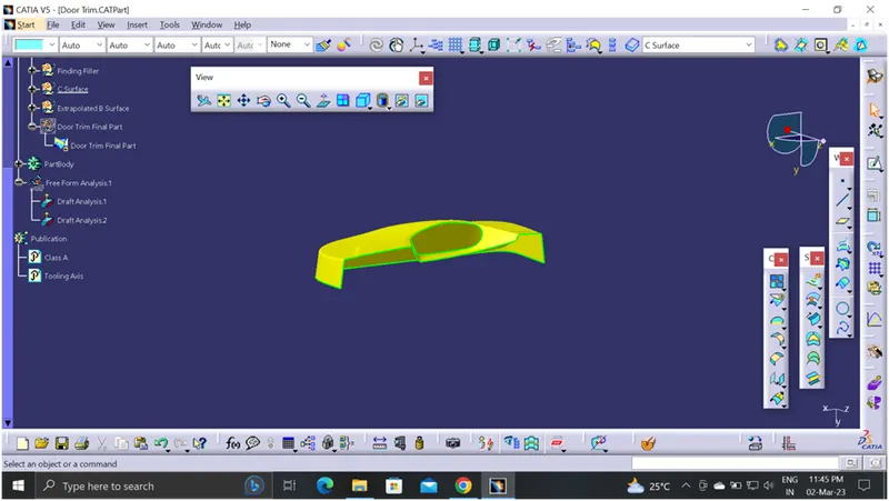
Procedure for creating draft analysis:
In the given class surface, have to check whether the given class a surface to clear the draft analysis, so that we have to decide whether the given product is manufacturable or not.
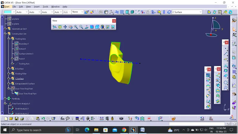
Creating a Tooling axis is mandatory for checking the draft analysis. On the reference of the Tooling axis only our draft analysis should perform. For creating tooling axis first analyse the given part in X, Y & Z view point and decide the maximum possibility to create the given part.
Step 1: checking the possibility of tooling axis in X, Y & Z direction.
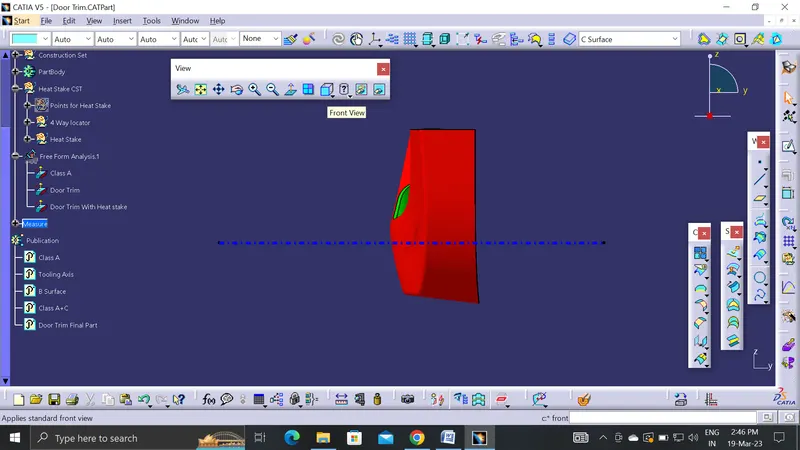
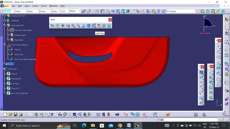
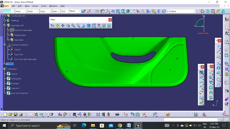
In X – Direction, Maximum part should be producible but side wall not visible clearly.
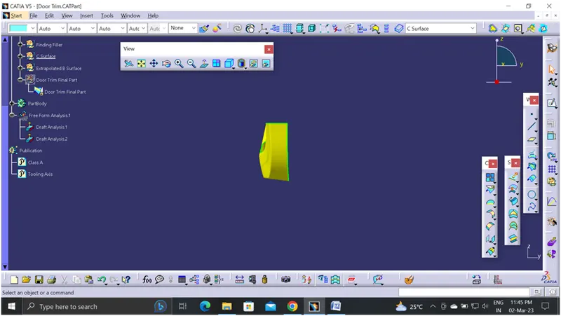
In Z – Direction, the part looks not a clear dimension so the part should not manufacture under this condition.
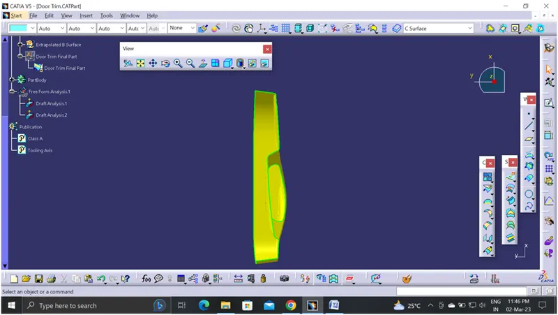
In Y- Direction, it's clear to see all the dimension and proper structure of the part.
Tooling Direction: "Y"
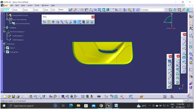
Step 2: To Create a Tooling Axis Extract the Flat surface and using Point command > on surface. Select the surface of the Part and make a point on it.
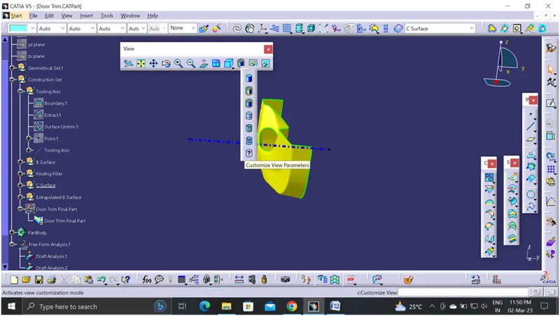
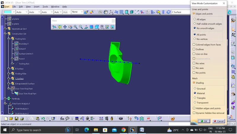
Step 3: For creating the draft analysis, first select the "Customize View Parameters" and select the "Material" option
Step 4: Select the Insert > Analysis > Feature Draft Analysis
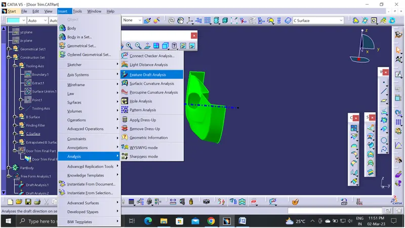
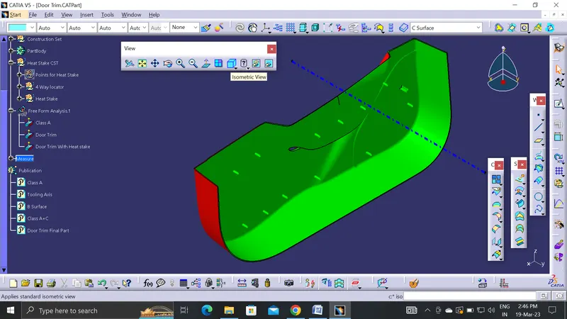
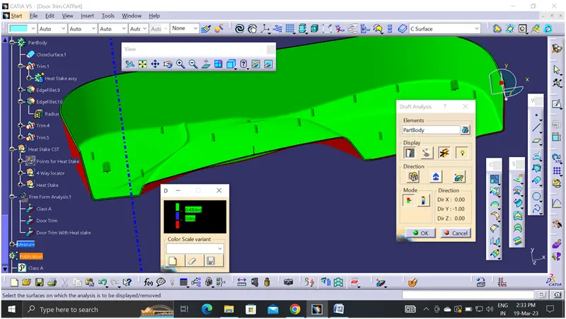
Step 5: Click the "Compass" icon and drag the compass on the Tooling axis and locking it. Make the draft angle as 3 deg. If the Draft angle is more than 3 deg. It shows a Green colour and 0 deg it shows in Blue colour. If the Draft angle is less than 0 deg its shows in Red colour.
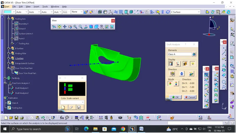
Step 6: Finally our Class A Surface pass the draft analysis test.
Step 7: Creation of B surface, first we offset the Class A surface at a distance of 2.5mm. While offsetting some portion are missing. We recreated the parts using multi-section command.
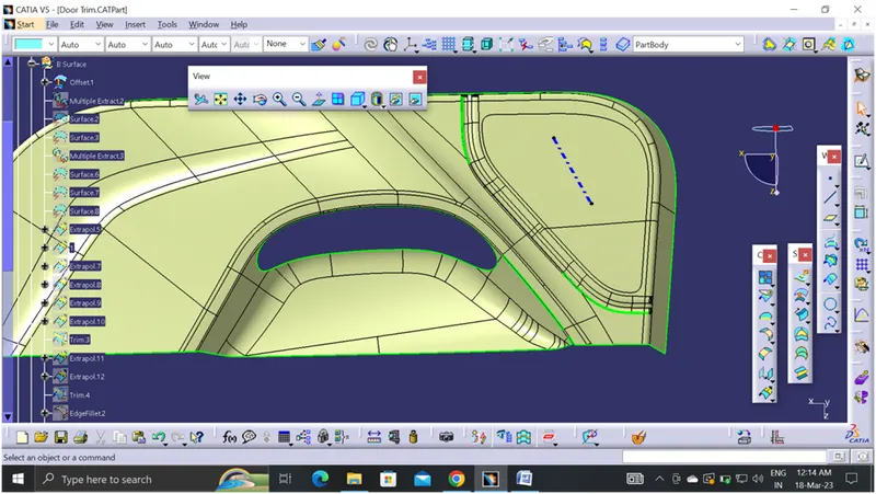
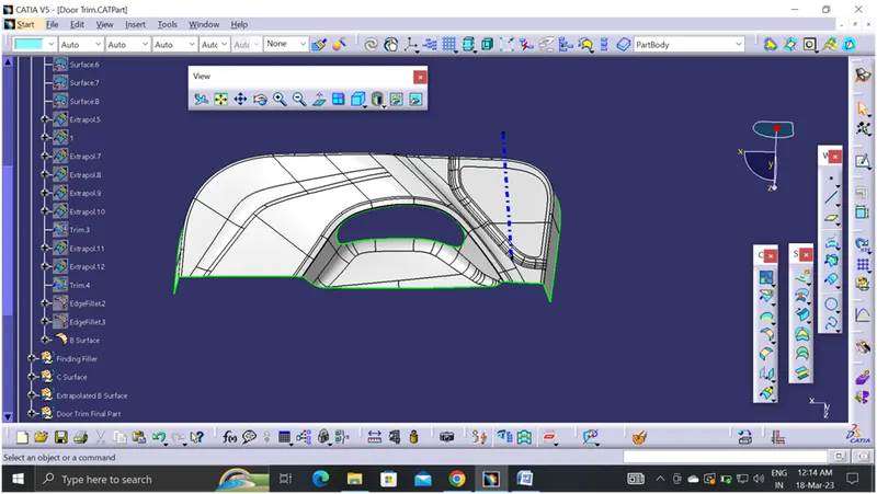
Step 8: Now creating the C surface, Take a reference boundary option from the A surface we use sweep command and using reference surface method we created the C surface.
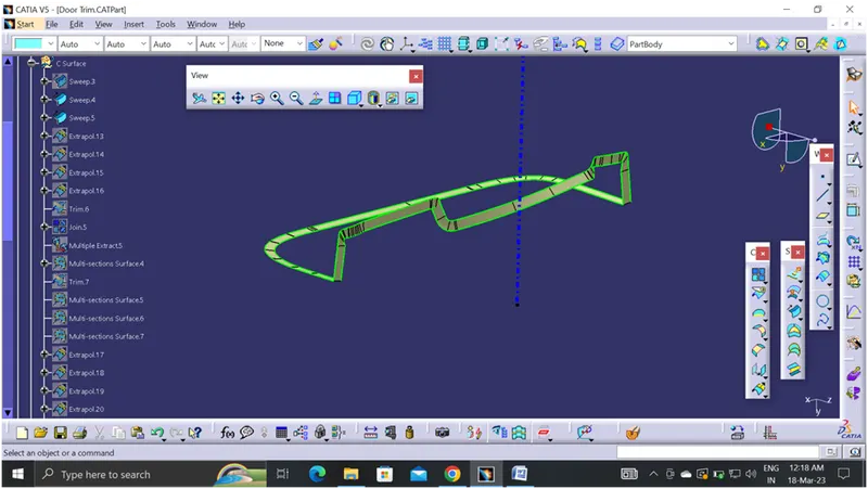
After creating the complete C surface, tried to join the Class A with C surface. At that point facing issue in joining. So we remove such point and recreated it using multi section option.
We check the draft analysis of final output class C surface and found some portions are not clear the draft analysis. So we removed that part and using draft direction method we created the part and join with class c surface. Once again check the class C now it's improve the class C surface. However some portion still in negative draft we create reference surface method in Profile 1 but it also not clear. We tried all the possibilities but nothing will clear the draft analysis. So we take a reference of maximum clearing surface and precede the challenge.
Step 10: Now going to trim the Class A+C surface with B surface. Its not trimming. For that going to extrapolated the Class B surface and trim with Class A+C surface obtained the closed body.
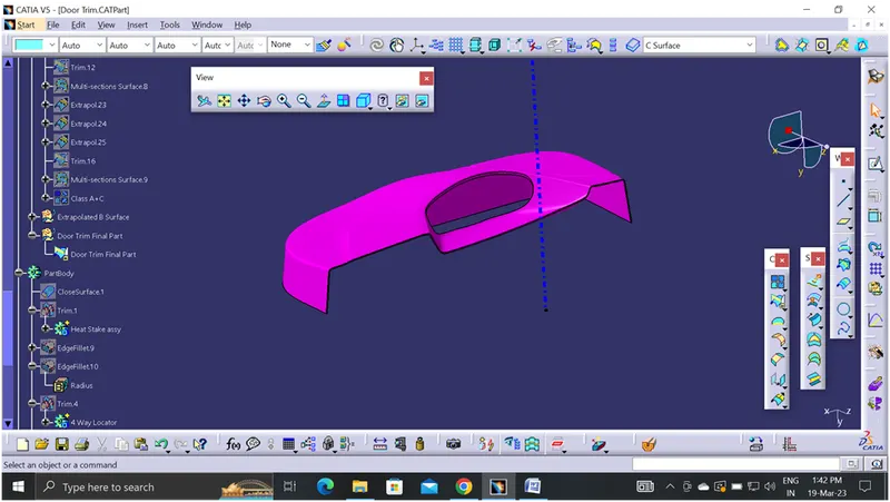
Step 11: Same procedure is follow the final part. This means joining of Class A, B Surface & C Surface.
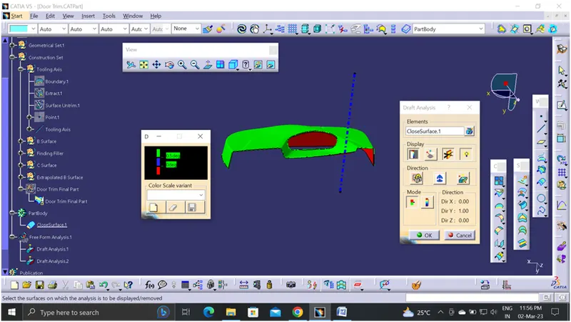
The sweep we using as "reference surface method" and we sweep the entire boundary in single shot, so some irregularities are formed the Class C Surface. Hence some of the portion of C is Red Colour. In that portion we tried to clear the draft analysis in various methods but it's not clearing. So we go with the maximum portion covering area.
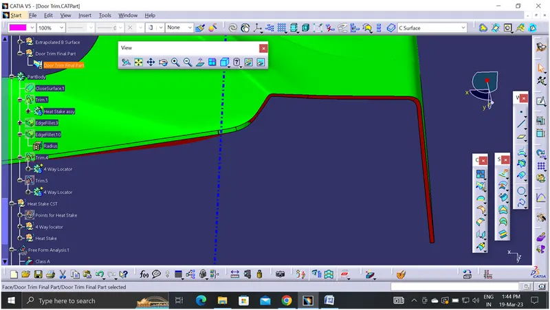
Step 12: Create a body and using part workbench using close surface command select the door trim surface and make it as part body.
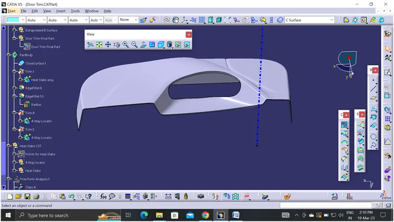
Step 13: Now creating the Locator and Heat stake. Points are already created in the given surface so we refer the point as an input.
Using extract command extract the B surface and creating the plane based on the surface. Draw a sketch in that plane for creating 4 way locator.
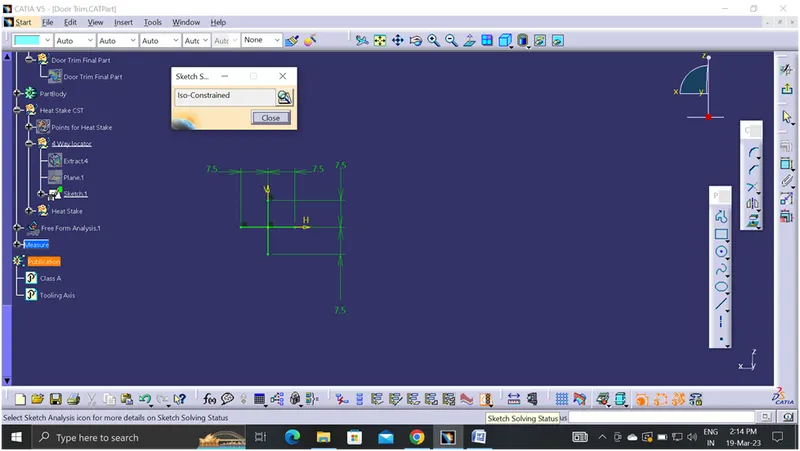
Step 14: Using Pad option and creating at a height of 20mm.
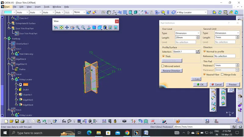
Step15: Make a draft angle of 0.5 degree and also create the chamfer of the 4 edges at a dimension of 3mm and 45 degree.
Then creating edge fillet radius is 0.25mm which is minimum range.
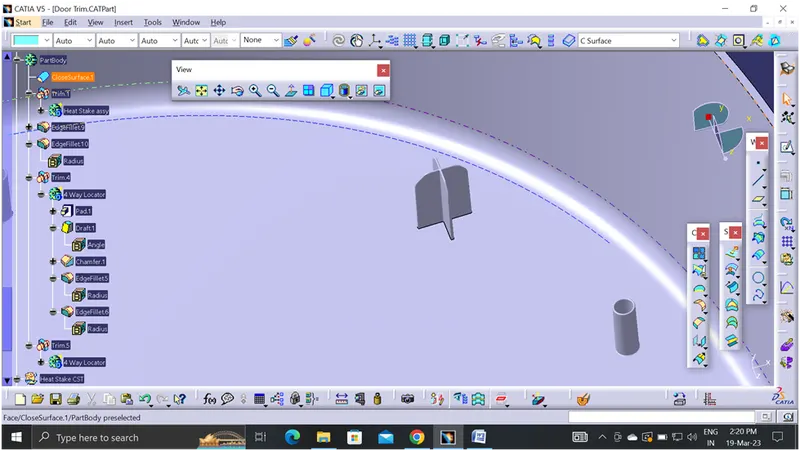
Step 16: and move the 4 Way locator an another side using translate command. Using point to point option move the other side of the part.
Step 17: Now creating the Heat stake, and make a sketch of dia.7mm. Using pad option and thick it to the inner area in 1.5mm inside. Draft the inner and outer surface of the heat stake and our neutral element is base at an angle of 0.5mm and make an angle of 0.25mm.
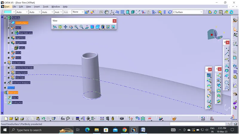
Step 18: Finally using union trim option we trim the heat stake & 4 way locators with the part body.
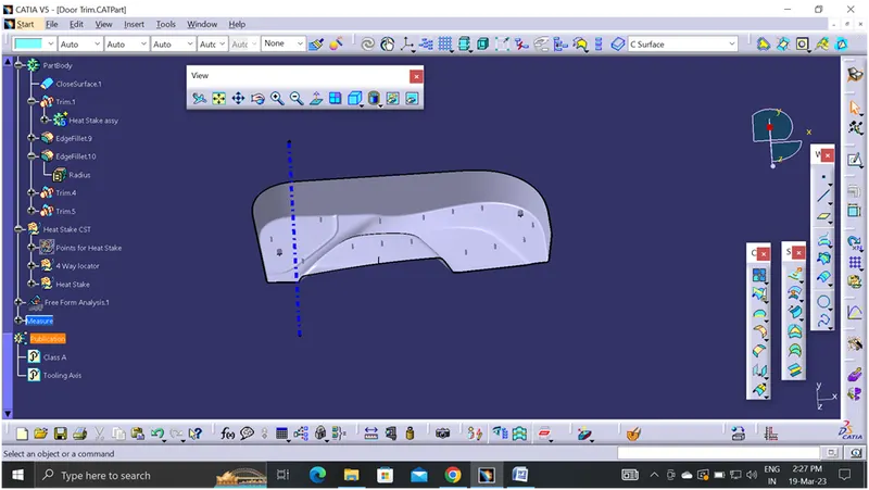
Step 19: Creating draft analysis of the closed body as same above method. The final part door trim and locator with heat stake finally clear the draft analysis.
View Modes: