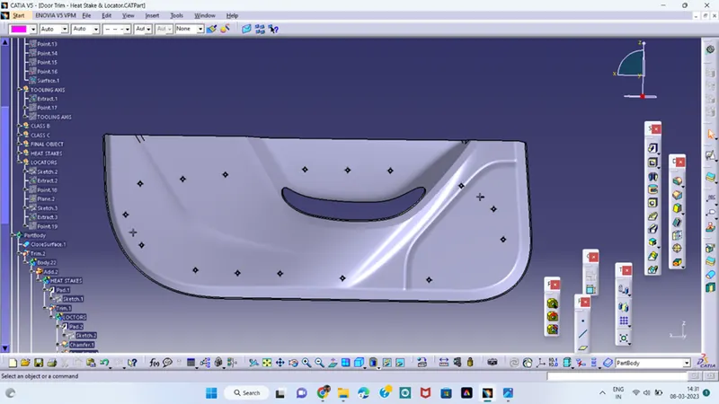
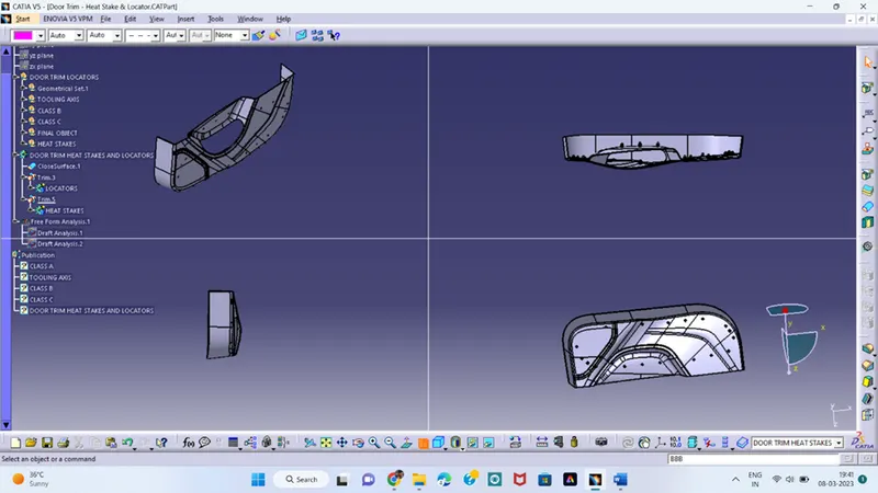
Week 9 - Project_1 - Door Trim Lower with Engineering Features
CHALLENGE 3
CREATION OF HEAT STAKES AND LOCATORS
AIM: To Create the Door Trim Lower Plastic component through the given Class-A surface. To begin with, the tooling axis for the given Class-A Surface should be created meeting the requirements of the draft angle and at the end perform the Draft analysis on the model.
Create the close body for the given class A surface and create the dog house and follow some procedures and rules.
- TOOLING AXIS
- DRAFT ANALYSIS
- CLASS B
- CLASS C
- FINAL BODY
- HEAT STAKES
- LOCATORS
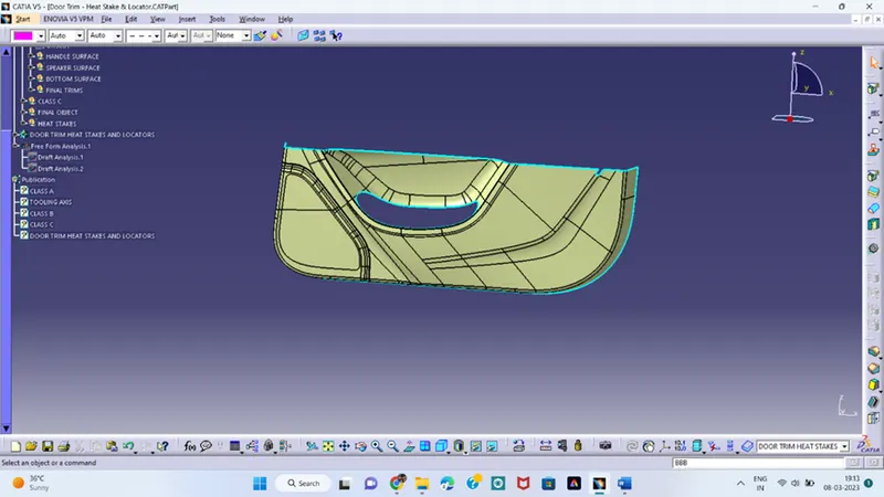
Given surface
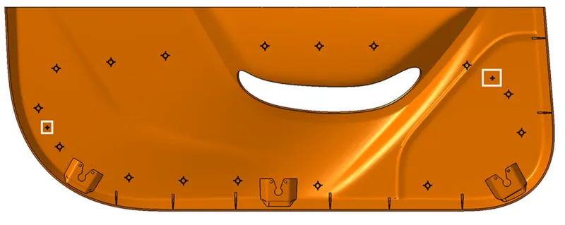
Take this surface as a reference model and create the close body and also heat stakes and locators as per the given surface reference.
CLASS A:
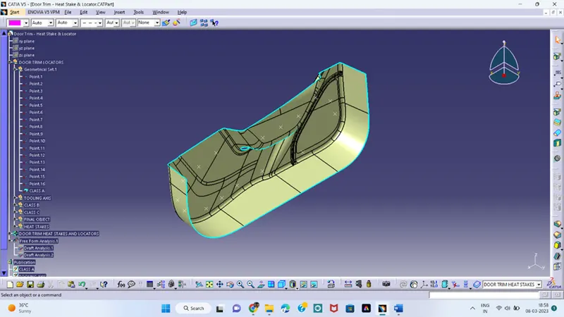
From the given class A surface we can create the tooling axis.
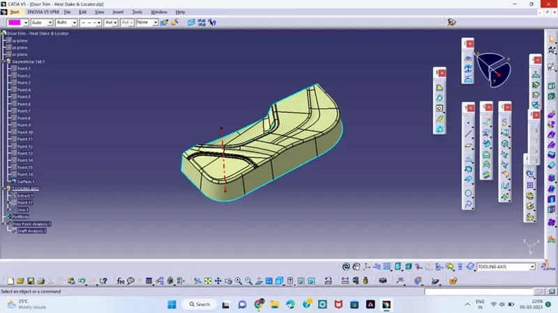
TOOLING AXIS;
Tooling axis is the direction in which the core and cavity opens in the tooling direction.
- Extract one flat surface, create a point.
- Create a line normal to the extracted surface using the point.
- The line which we created from the surface i.e tooling axis
- Next is to perform the draft analysis using the tooling axis.
DRAFT ANALYSIS:
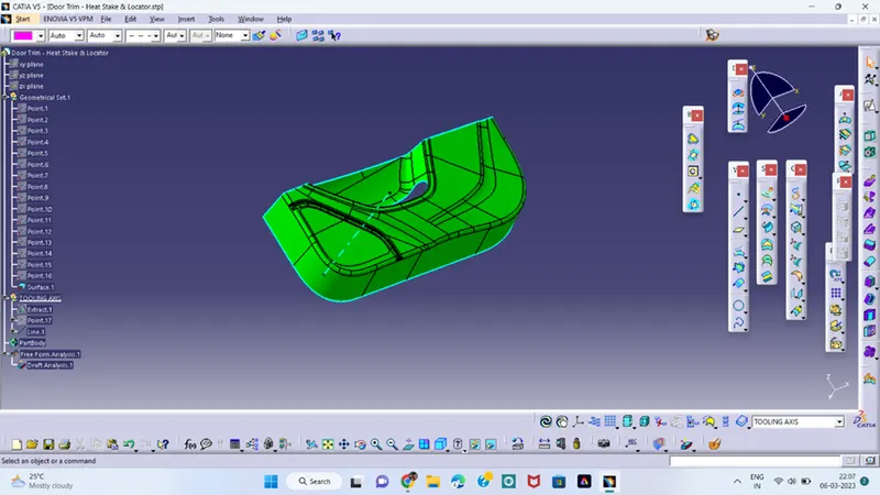
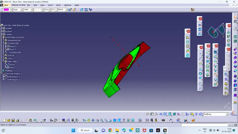
Draft analysis technique is used to analyse the whether our part model created in CAD is manufacturable based the draft condition applied.
- First go with the draft analysis command and place the compass at the tooling axis and click the compass option in the draft analysis table.
- Click on the component and some colour changes in the component.
CLASS B:
CLASS C:
FINAL BODY:
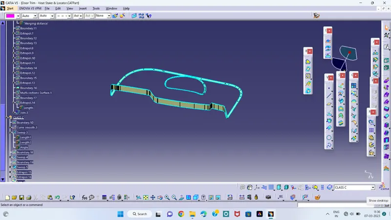
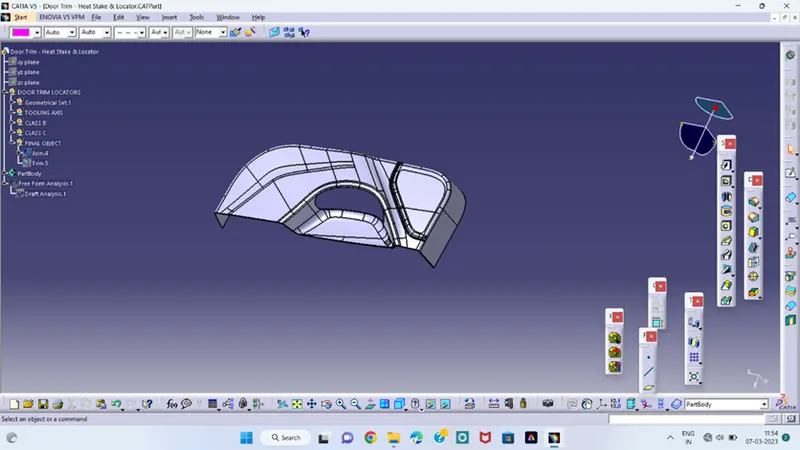
- in this join the class C and class A and trim with the class B.
- define in the part workbench and create the close body.
- From this close body we design the heat stakes and locators.
- After creating close body check draft once again whether the created part is correct or not.
HEAT STAKES:
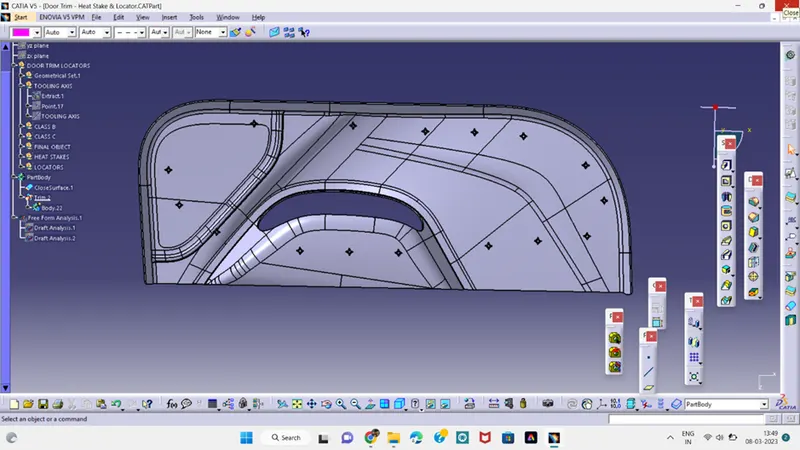
Heat staking is a method of joining two or more parts, where at least one is made out of plastic. The bond is made by partially de-forming the plastic part to fix the other. The heat stake process is used in many high technology fields and consumer products manufacturing and offers many benefits.
- Create a plane parallel to the point.
- Draw the circles with inner dia is 5mm and outer dia is7mm
- Define in part workbench and pad the circles which drawn.
- And create the locators with attaching the heat stakes.
LOCATORS:
Locators is used to attaching component and improve the strength of the component for the assembly.
- Create the plane which parallel to the point.
- Draw the lines perpendicular to each using three dimensional and the geometry.
- we refer to six coordinates with total 12 degrees of freedom.
- Translational position along the X-axis
- Translational position along the Y-axis
- Translational position along the Z-axis
- Rotational position about the X-axis
- Rotational position about the Y-axis
- Rotational position about the Z-axis