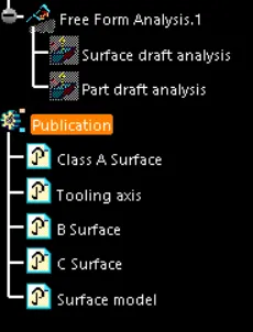
Door Trim Lower with Engineering Features
Aim:
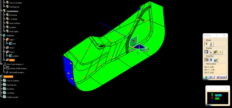
1. To create the Door Trim Lower Plastic component through the given Class-A surface. To begin with, the tooling axis for the given Class-A Surface should be created meeting the requirements of the draft angle and at the end perform the Draft analysis on the model.
2. To create the Heat Stakes and the locators considering the design rules mentioned in the video for the door applique.
Given Class A Surface:
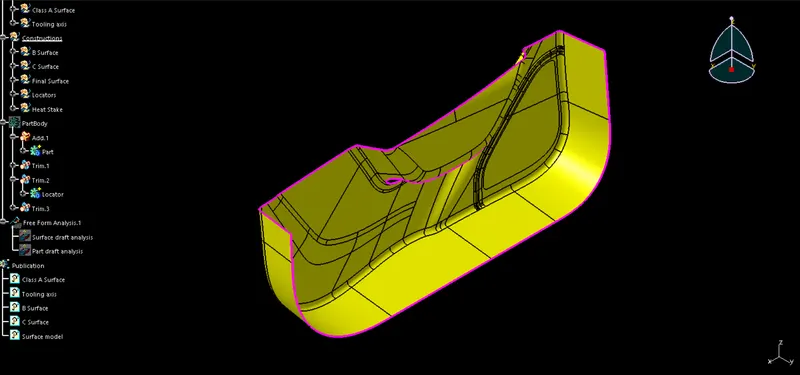
Check the connectivity of Class A Surface.
Using the connect command, make sure there are no gaps between the components. We may physically inspect it or use the border command to do so. One outside and two inner circular limits make up its three borders.
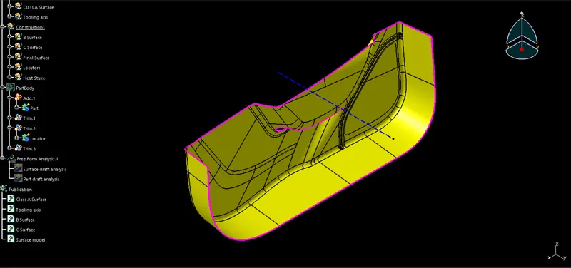
Find a suitable tooling axis and create one.
Look carefully to determine the ideal tooling axis. Verify each axis.
Bisecting method: This technique is used to generate tooling axes for that purpose. First, the direction of molding must be decided. Next, a fake tooling axis is created for the purpose of reference.
The surfaces that potentially cause issues are chosen in this manner, and intersections in the x and y directions are taken. Using these curves, we create two lines, from which we create a bisecting line in both the x and y directions.
Tooling axis cleaning x-direction and tooling axis clearing y-direction are the terms used to describe how the clearing is carried out.
We must then draw a final line that splits the two tooling axes in the X and Y directions.
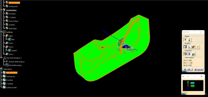
Draft analysis of Class A Surface:
Use the Featured Draft Analysis tool in the tools to now analyze the draft. After locating the compass and aligning it with the tooling axis, click on the lock symbol after aligning, and then click again on the surface after opening the draft analysis toolbox.
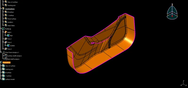
B Surface:
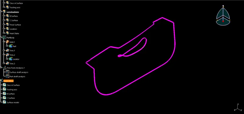
C Surface:
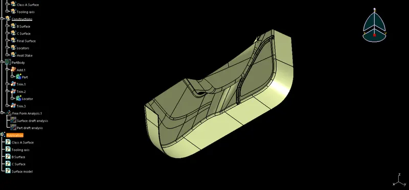
Final Surface Model:
2D Sketches:
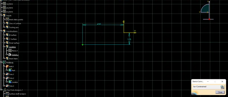
Locators
Heat Stakes
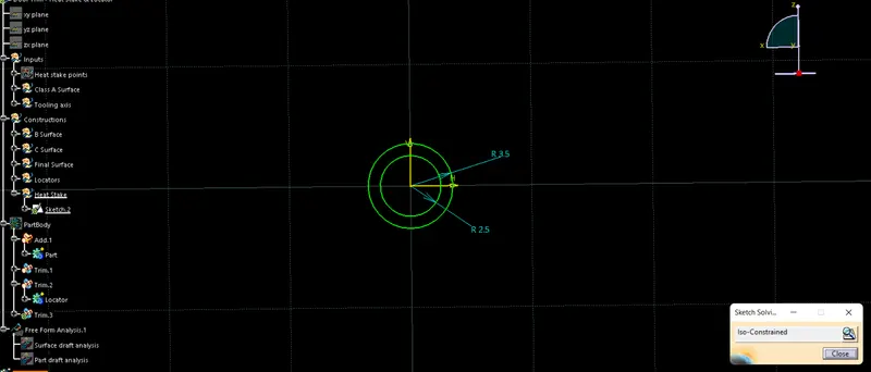
3D Part:
Isometric view
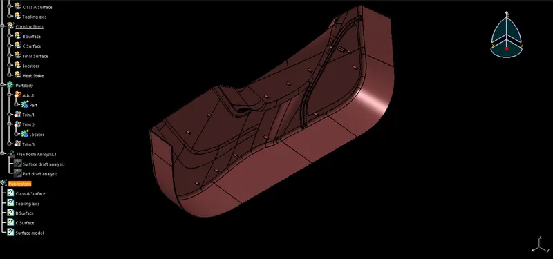
Front view
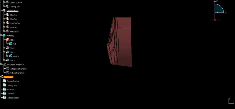
Rare view
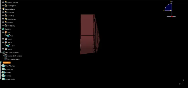
Left side view
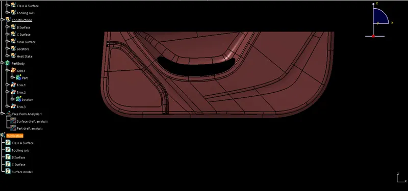
Right side view
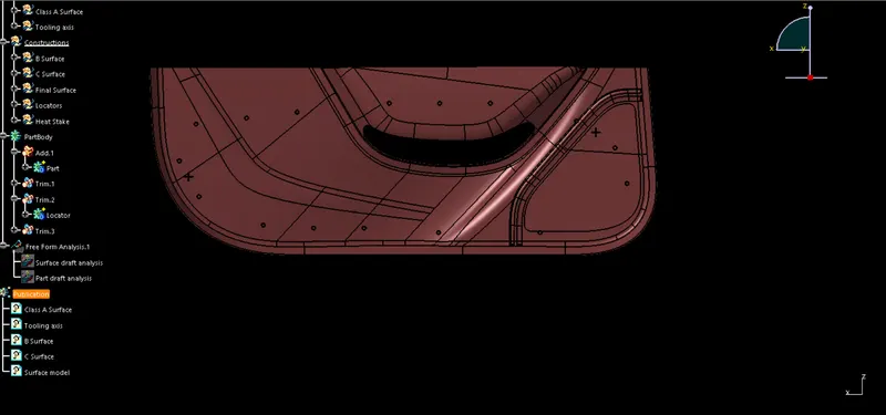
Top view
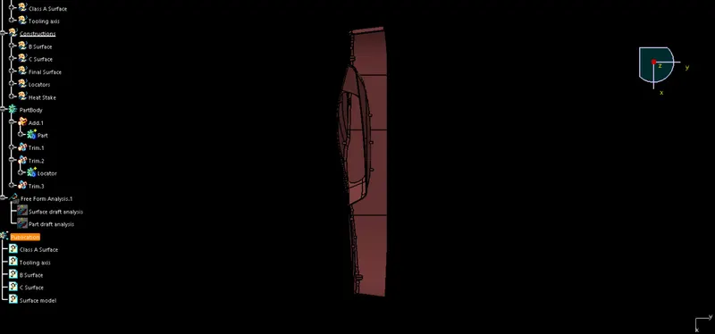
Bottom view
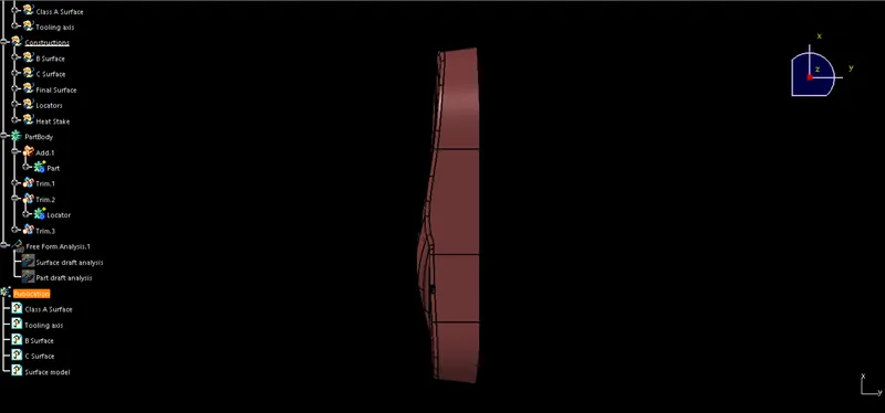
Draft analysis of part:
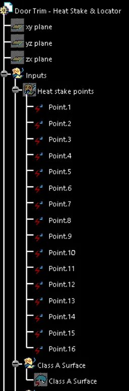
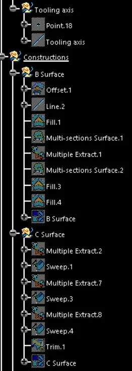
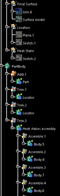
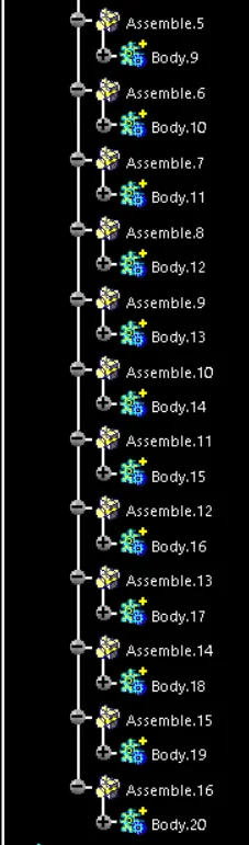
Expanded tree: