Week 9 - Project_1 - Door Trim Lower with Engineering Features
Aim :
To Create a the DOOR TRIM LOWER Plastic component through the given Class-A surface.
Also Create the Heat Stakes and the locators considering the design rules mentioned in the video for the door applique.
Take the Thickness of the component to be 2.5 mm.
STEPS TO BE FOLLOWED :
- Creating the tooling axis.
- Draft analysis of Class A surface.
- Creating Class B surface.
- Creating Class C surface.
- Close Surface and Create solid body.
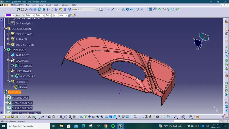
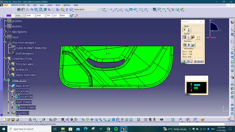
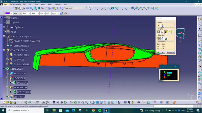
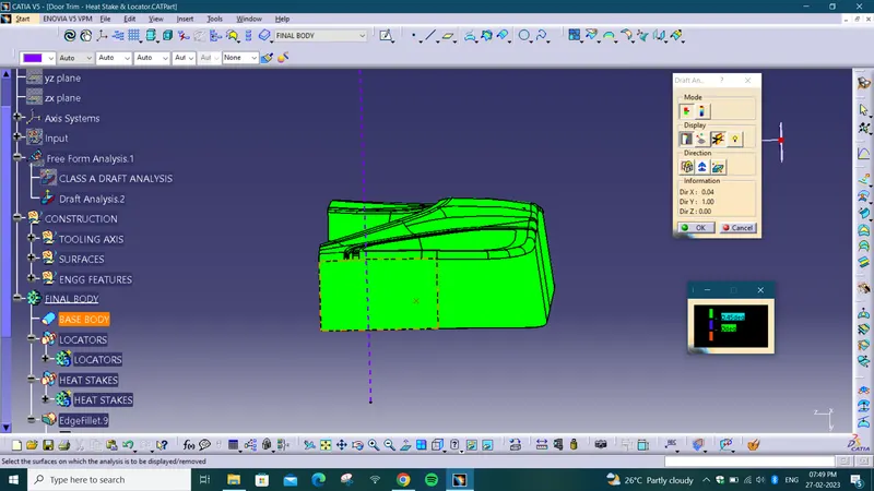
- Draft analysis of Solid body.
- Engineering features {Heat stakes and Locators} are created.
- Draft analysis of Solid body with engineering features.
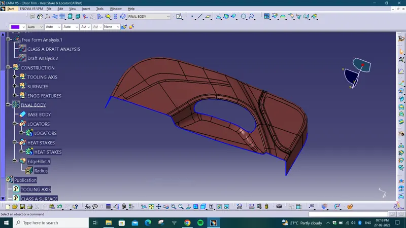
Given Class-A Surface :-
In automotive design, a class A surface is any of a set of free form surfaces of high efficiency and quality. It gives the aesthetic of the component which is created by the styling team and gives to the part design engineer to create the part with all engineering aspects.
CREATING THE TOOLING AXIS :
- Class-A surface is first analyzed to create the tooling axis or tooling direction that molds pull apart in injection molding. Tooling direction is important for plastic product design as it decides the direction for mold separation.
- First check the connectivity of the given Class A surface by using the Boundary or Join feature to visualized and repaired the open edges of the surface.
- And then, analyse visually the best suitable plane or surface for tooling axis.
- First check the connectivity of the given Class A surface by using the Boundary or Join feature to visualized and repaired the open edges of the surface.
- And then, analyse visually the best suitable plane or surface for tooling axis.
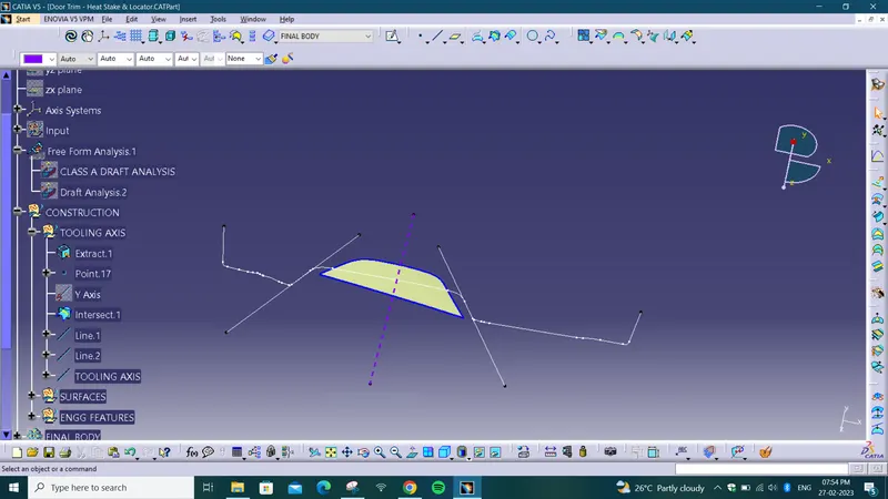
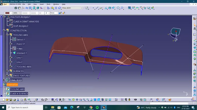
- TOOLING AXIS is created by bisecting the axis created on two intersections .
- The best tooling direction for the class-A surface is along y-axis direction.
- Flat surface on the center part is extracted for creating the tooling axis in y direction
- Then a line is created by BISECTING METHOD with the point and direction along y axis.
Publications :
“Publishing geometrical elements is the process of making geometrical features available to different users”.
“A publication acts as a reference to a geometric or datum entity in a CATIA V5 part or product”.
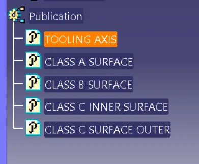
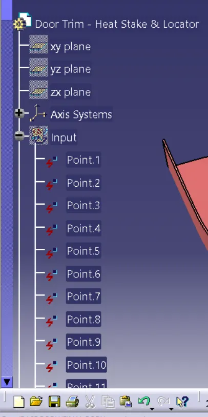
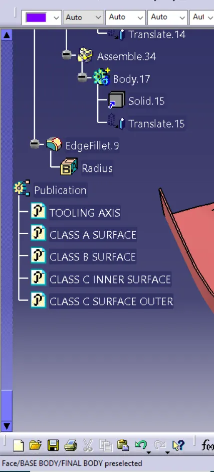
slecting the geometrical elements for easier to show or hide when we work on the catia so that we have to select the Class A,B,C Surfaces & Tooling Axis, after that go to the tools & Select the publication Click yes & Click ok, then we got the publication on the tree As shown in figure below.
DRAFT ANALYSIS OF CLASS A SURFACE:
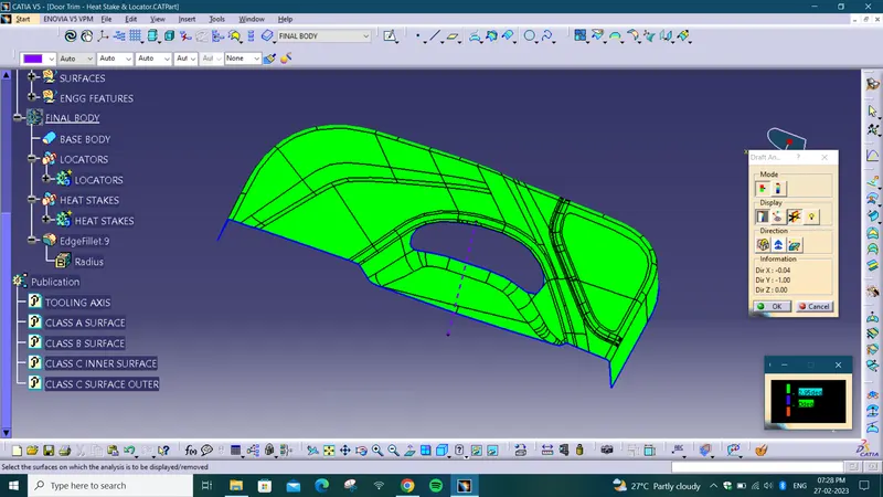
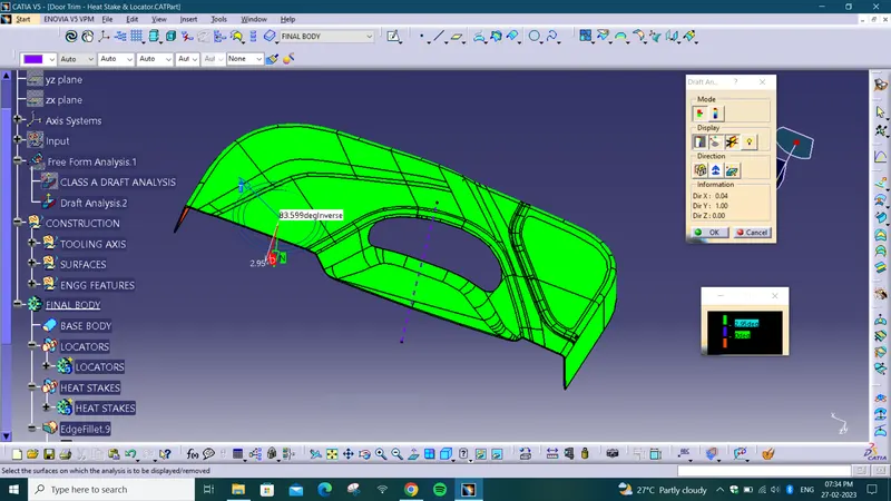
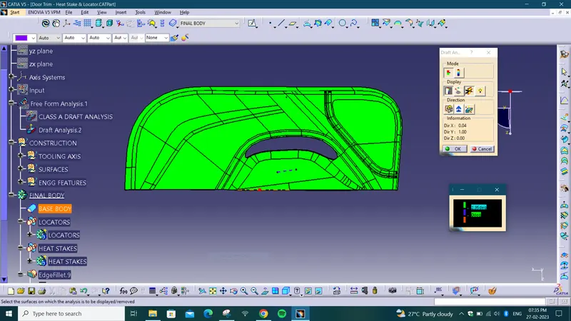
The Draft Analysis command enables you to detect if the part you drafted will be easily removed. This type of analysis is performed based on color ranges identifying zones on the analyzed element where the deviation from the draft direction at any point, corresponds to specified values.
- Before going to drat analysis go to customized view parameter >under mesh >check material and then click ok.
- Now for draft analyses go to insert » analysis » feature draft analysis.
- Use the compasss to define the draft direction.
- In the colour scale change the draft angle to 3 degree.
- The component changes to green in indication of passing draft angle.
- Use running point to check the angle on the component.
Class B surface :
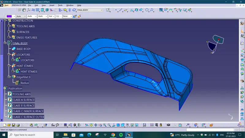
we offset the Class A surface and get the B surface body here we offset the 2.5mm value so we get the thickness is 2.5mm is mention in above so we offset the A surface for 2.5mm .
After the offset we get the surface but in that offset some patches of surface is missing so we required to solve it.
Class C Surface:
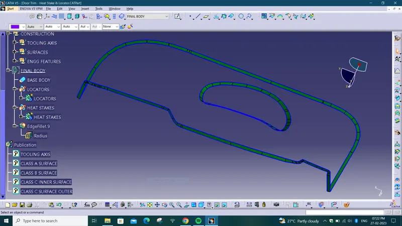
To create a Class C surface, first, extract the boundaries of the Class A Surface.
Now using the Sweep option create the surface. To perform this operation, Go to the Toolbar > Sweep > Profile type > Line > Subtype: With draft direction > Guide curve 1- (select the extracted boundaries) the in Draft direction (select the tooling axis) angle and length as 3° and 4mm respectively and click ok.
CLOSED SURFACE OR A+B+C SURFACE:
DRAFT ANALYSIS VIEWS OF SOLID BODY:
HEAT STAKE
Heat staking also known as thermoplastic staking is the process of joining two dissimilar materials together. In heat staking we use local heating and cooling to raise the temperature of plastic components and allow plastic reforming to be carried out. This reforming can be used in a wide variety of applications.
Thermal staking should be considered when the parts to be assembled are still in the design stage. Several configurations for boss/cavity design are available, each with specific features and advantages. Their selection is determined by such factors as type of plastic, part geometry, assembly requirements, machining and molding capabilities, and cosmetic appearance. Heat staking can be performed using wide range of thermoplastic materials including polypropylene, ABS, polycarbonate and many others.
The integrity of a thermal staked assembly depends greatly upon the geometric relationship between the boss and the thermal tip. Proper design will produce optimum strength with minimum flash.
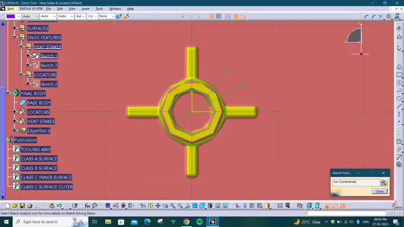
Heat Stake Sketch :
Take 5 & 7.5mm Dia Circles As Shown in figure below.
Here heat stakes created with draft 0.5 degree, fillet radius is 0.3mm and wall thickness is 2.5mm.
heat stakes designed by following the design rules.
LOCATORS
Typically, locating pins are used for controlled, fine tolerance positioning of a work piece.
A 2-way locating pin restricts motion along 1 axis (or 2 degrees of Freedom), like a round pin in a slot. Likewise, a 4-way pin restricts 4 degrees of freedom along 2 axes. A round locating pin located concentrically in a hole is a common application of a 4-way pin, and helps to further secure the piece.
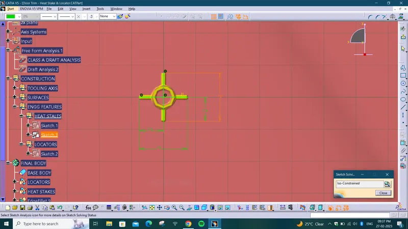
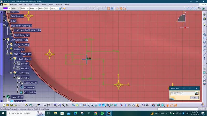
Here 4-way locator created with thickness 1mm ,draft 0.5 degree and the fillet value is 0.3 mm .
4 way Locator Sketch :
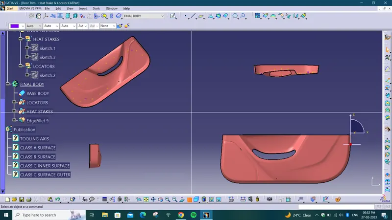
FINAL BODY VIEWS:
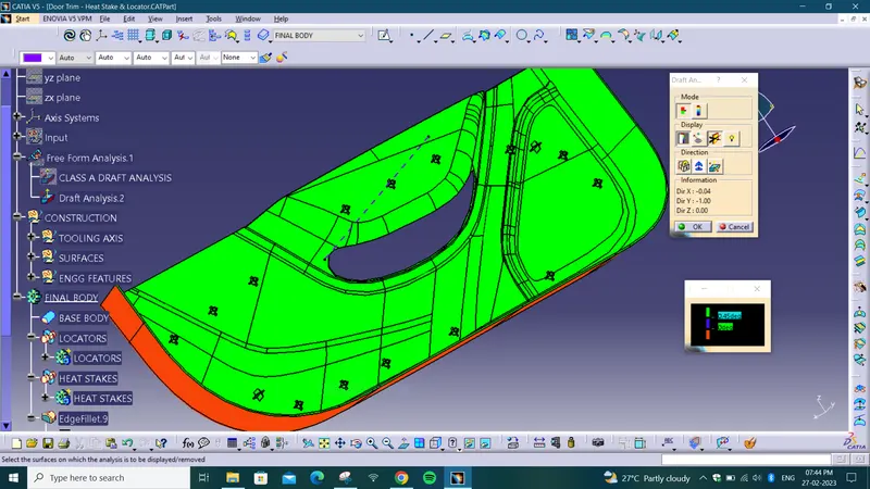
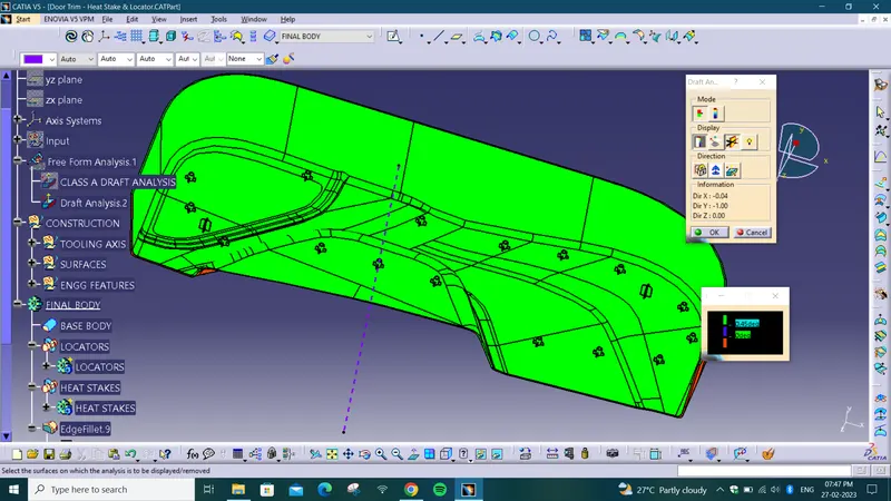
FINAL BODY DRAFT VIEWS:
- Draft analysis is cheked with 0.45deg.
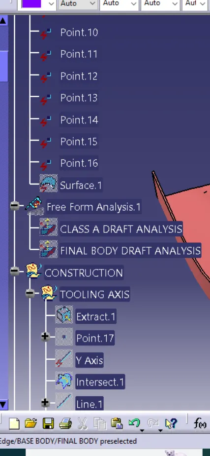
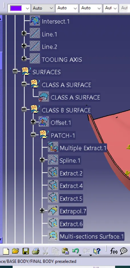
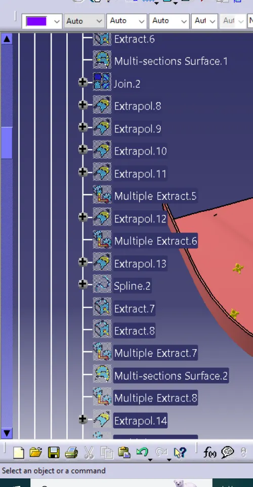
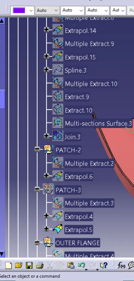
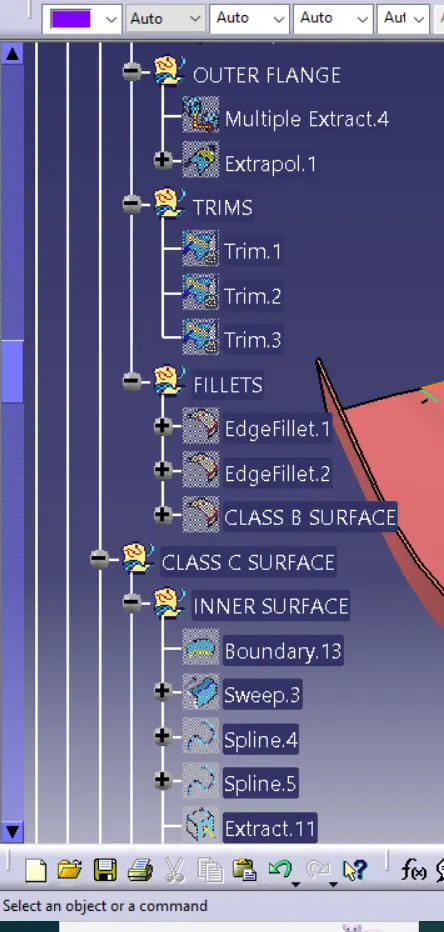
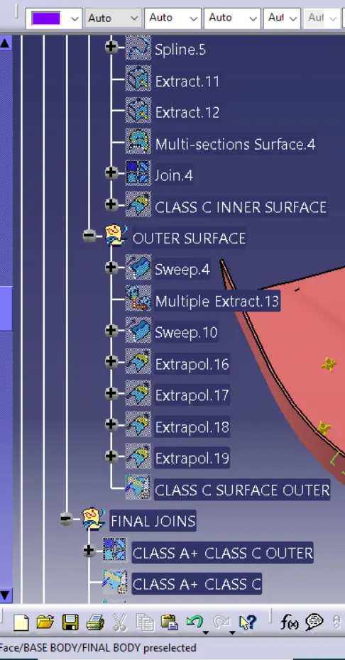
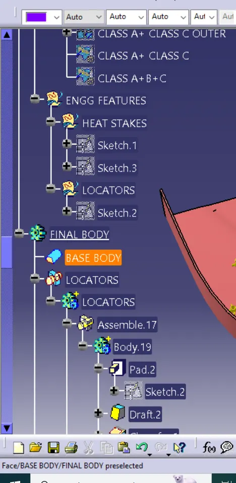
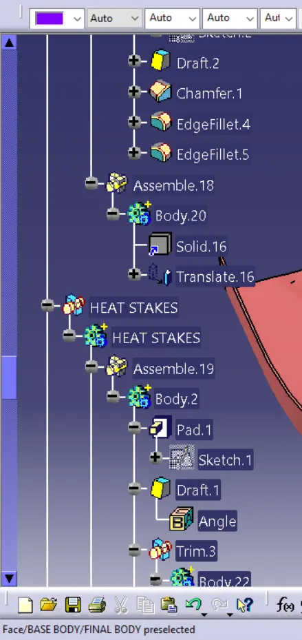
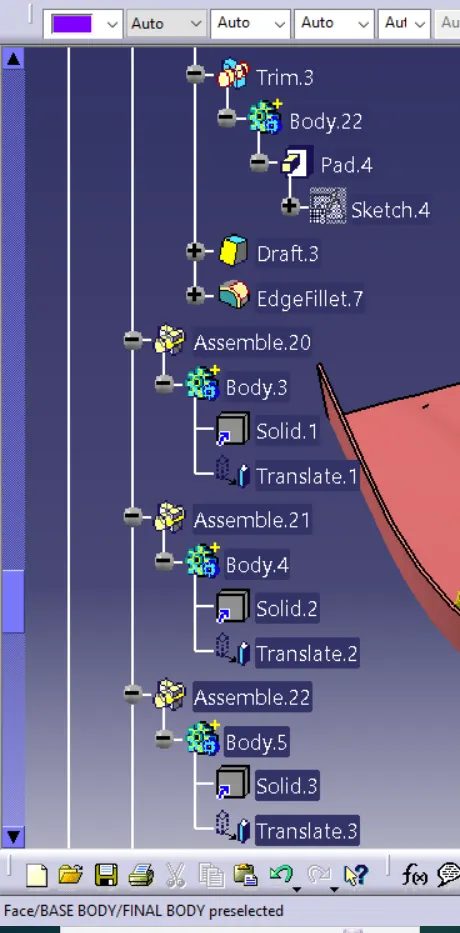
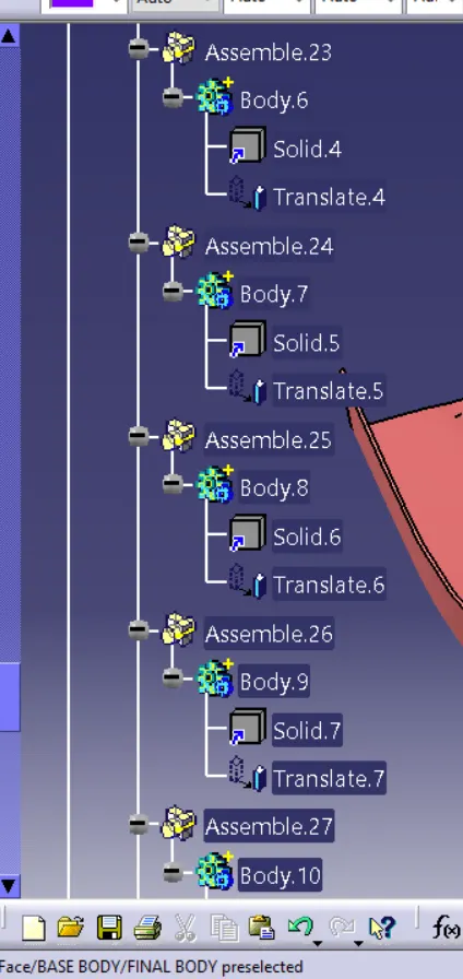
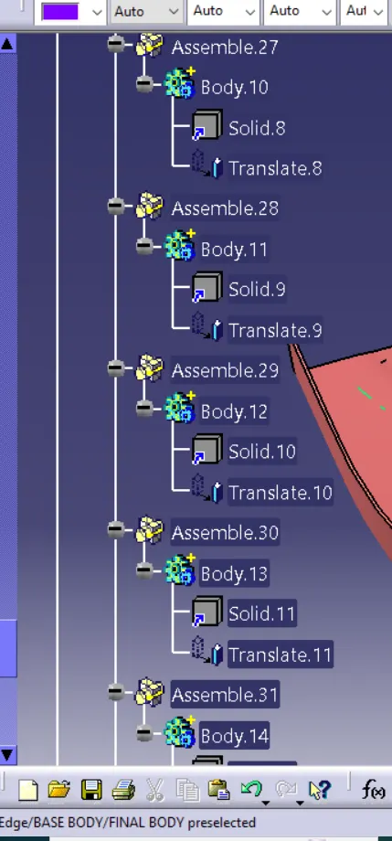
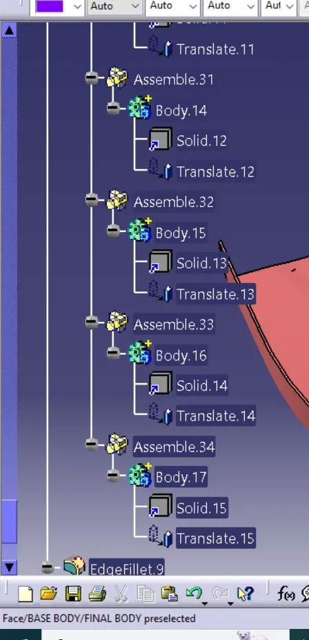
TREE STRUCTURE:
CONCLUSION
Created the Door Trim Lower Plastic component through the given Class-A surface. The tooling axis for the given Class-A Surface is created meeting the requirements of the draft angle and at the end performed the Draft analysis on the model.
Create the Heat Stakes and the locators considering the design rules mentioned in the video for the door applique.