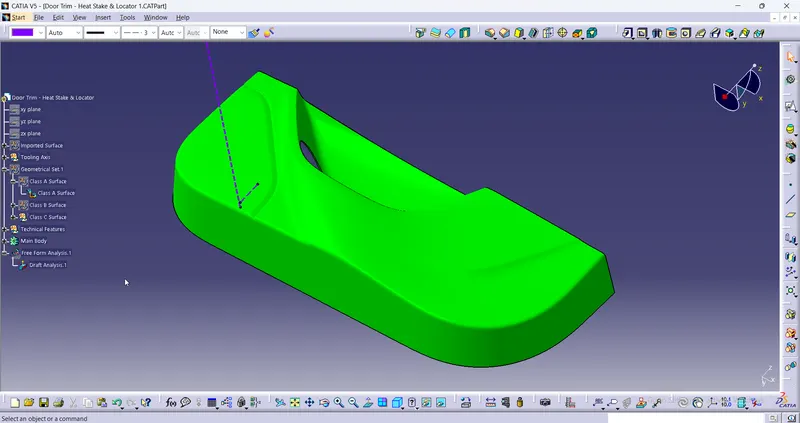
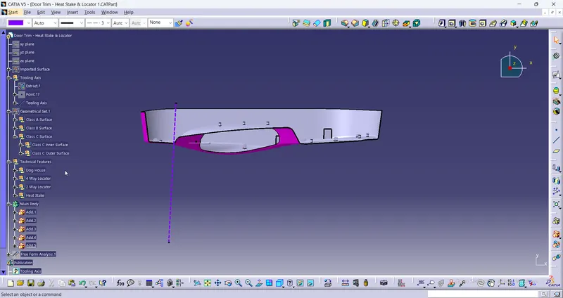
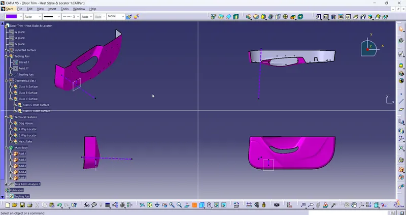
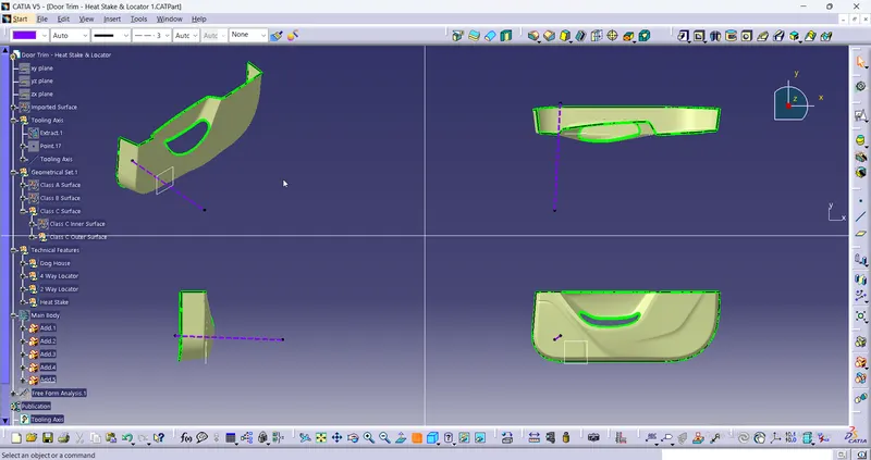
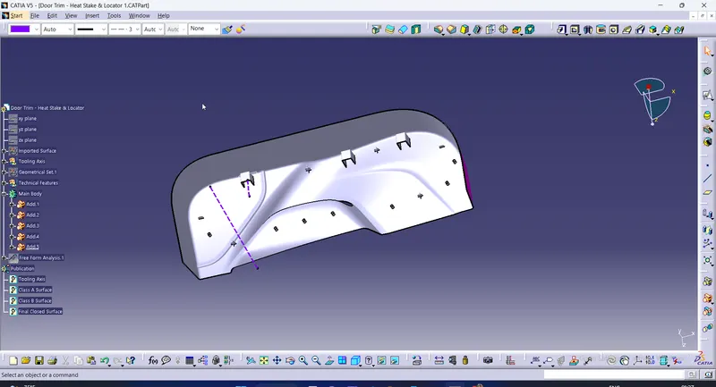
The door trim Class A surface is imported and published as Class A surface. Then it is offset to required value to inwards and by using the surface toolings like multi section solid, extract, join. trim split, the Class B surface is created. The patches formed during the offset are cleared and it is published as Class B surface. By using the sweep command the Class C for both inner boundary and the outer boundary are created. Finally the closed surface model of door trim is created by using Trim and the join commands.
Now the surface is converted into a solid component by using the closed solid command in the part workbench. Some of the Technical features like locators, heat stakes, Dog House are created on the inner part of the solid model.
4 way locator - A round locating pin located concentrically in a hole is a common application of a 4-way pin, and helps to further secure the piece. 4-way means to prevent the movement at 2 axes (+X, -X, +Y and -Y) on the plane.
2 Way Locator- A 2-way locating pin restricts motion along 1 axis (or 2 degrees of Freedom), like a round pin in a slot.
Dog House - Dog house is an engineering feature used in plastic trim design. Dog houses are used as supporting feature. Sometimes other engineering features like snaps; locators etc. are mounted on them to increase their strength.
These engineering features are created as per the engineering moulding dimensional standards which includes appropriate dimensions along with the edge chanfering and filleting features. These features are drafted to minimum of 3 degrees so that it could not be affected while removing the mould.
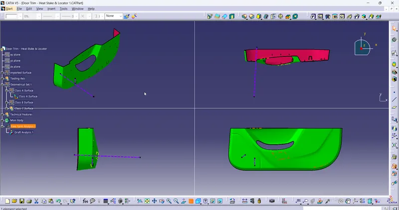
The tooling axis is created by using the any methods. here the normal to surface is used. Bisecting method can also be used for creating the tooling axis. The surfaces which tends to be affected while seperating the mould and cavity are concentrated. The lines are drawn in the direction of those surfaces. The bisecting line for these two lines are drawn which forms the tooling axis of this Door trim.
The draft analysis for the maximum of 3 degrees are done by mounting the drafting coordinate axis on the tooling axis. Then the components is checked whether it clears the draft analysis or not.